REVIT_Usage of Elements & Properties_Week 3
1) Use the project file created from Week 2. Use it for this assignment. Based on your layout from week 2, using floor tool under architecture tab and select the floor with appropriate material and thickness using the property browser create a layout in the Ground floor Level. Align the floor plan with grids created from week 2
AIM:TO SELECT FLOOR WITH APPROPRIATE MATERIAL AND THICKNESS USING THE PROPERTY BROWSER AND TO ALIGN THE FLOOR PLAN WITH GRIDS
TOOLS/COMMANDS USED:
- Properties browser
- Floor tool
- Archirtecture
- Open
- Grid
- Edit
PROCEDURE:
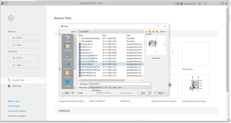
STEP-1:Open REVIT software and click on open project then choose the required project I.E,week 2 saved project and open the file
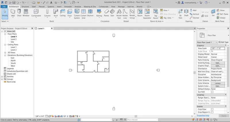
STEP-2: A layout of is opened on the screen now go to archietectural bar
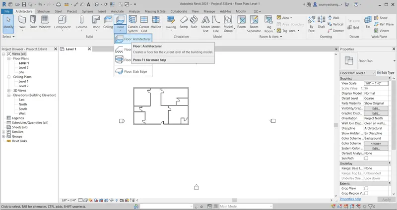
STEP-3:Now choose floor tab and click on floor architecture to add the floor into layout
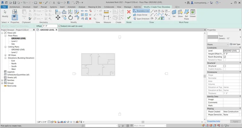
STEP-4:After selecting floor architecture select pick lines to select the boundary of the layout to which floor to be added
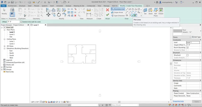
STEP-5: Now click on the boundary of the wall to add floor to layout by using pick lines toolbar
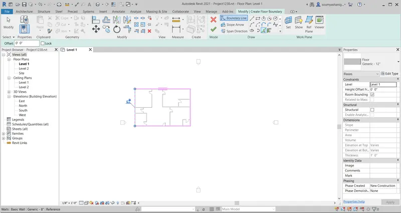
STEP-6:After selecting all boundaries of the layout click on FINISH EDIT MODE to change the layout
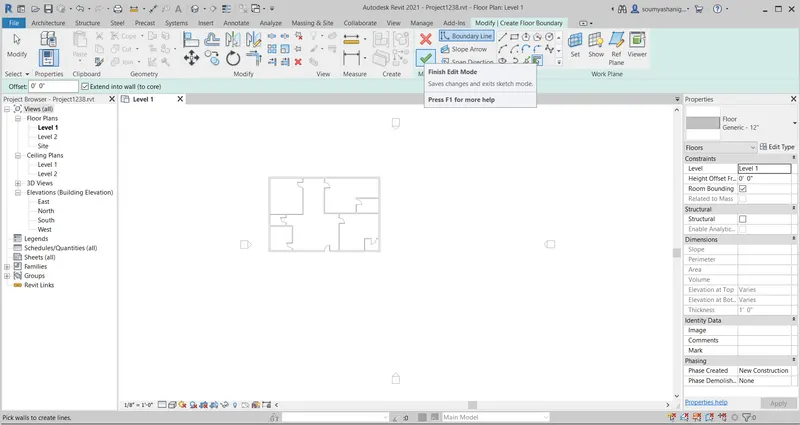
STEP-7:After clicking then the layout will be visible in this way
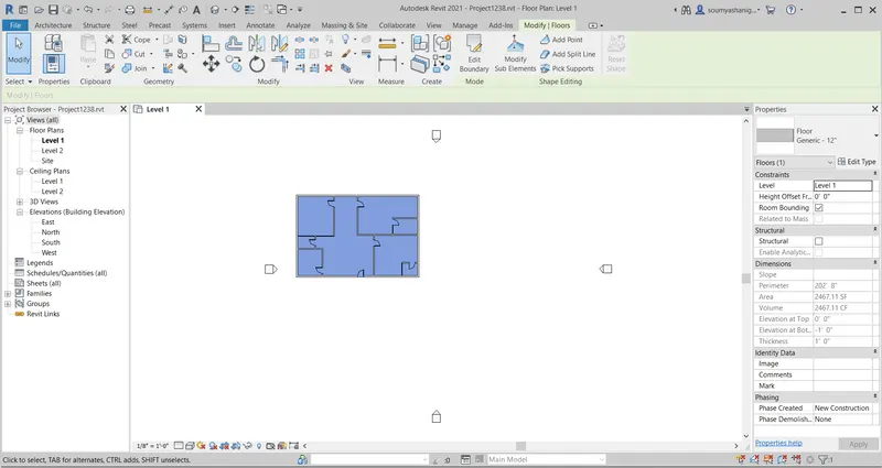
STEP-8:now go to floor properties and choose the required floor and thickness to be added to the layout by clicking edit option (one can create duplicate thickness of floor material) and click on apply ond press ok
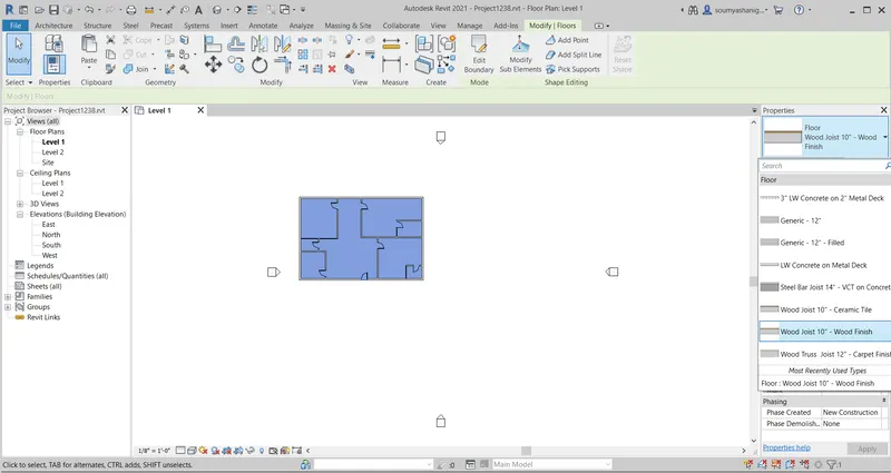
step-9: the required floor is obtained
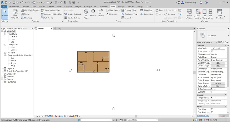
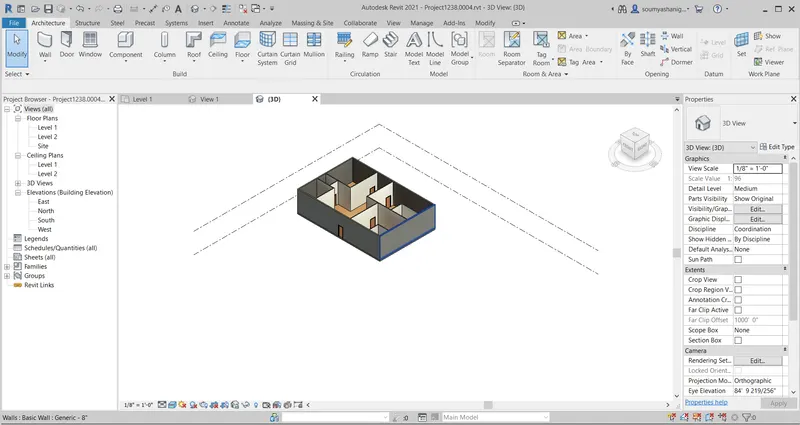
STEP-10:3D View of the layout is visible by clicking 3D default view by chosing 3Dview option from view tab
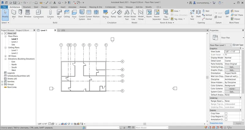
STEP-11:To Align grids to floor layout select the archietectural tab and select grid option
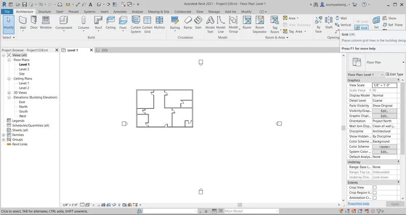
STEP-12: draw the longitudinal and traverse grid lines to the floor layout and name them as A,B,C,D,E ETC FOR TRAVERSE G rid and 1,2,3,4,5 etc for LOngitudinal grid
STEP-13:now view the layout in 3d view
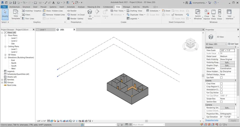
RESULT: Floor material and thickness is added to the layout and grids are alligned to floor layout and the layout is viewed in 3D view successfully
2) Add walls based on the floor layout. Pick lines or use the draw tool to modify the boundary of walls. Use the property browser to select appropriate material and thickness for walls. After creating the walls verify using the property browser to see if the top and bottom of the walls are constrained.
AIM:TO ADD WALLS BASED ON FLOOR LAYOUT AND TO MAKE USE OF DRAW TOOL AND PROPERTY BROWSER TO MODIFY BOUNDARY OF WAL AND TO SELECT APPROPRIATE THICKNESS AND MATERIAL OF WALL AND TO VERIFY THE TOP AND BOTTOM OF WALLS ARE CONSTRAINED OR NOT BY USING OF PROPERTY BROWSER
TOOLS/ COMMANDS USED:
- Properties browser
- Archietectural tool bar
- Edit
- Constrained
- Wall Archietectural
- 3 D view
- Partition interior wall
PROCEDURE:
STEP-1:Open the revit software and open the previously created layout of 60'x40'
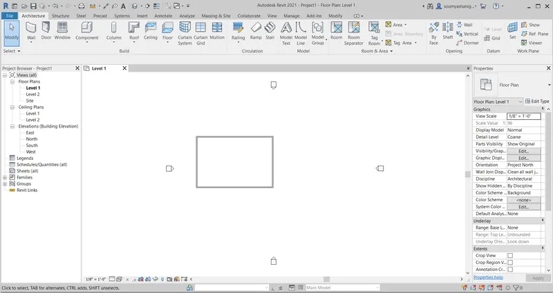
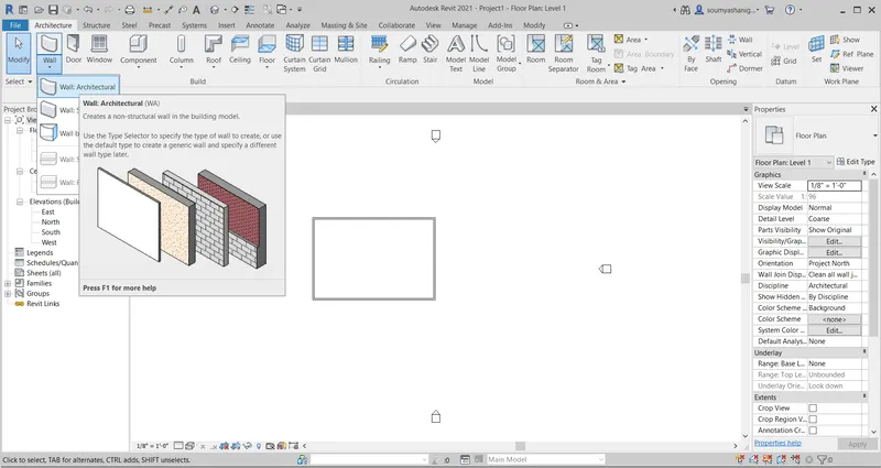
STEP-2:Now go to architectural tab and click on wall tab and select archietectural wall bar
STEP-3:Now go to properties browser to set the type of wall and wall thickness .now select the interior wall type of required thickness
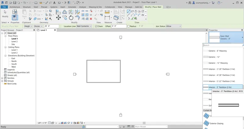
STEP-4:after clicking on interior -5'' partition one can make neccessary chnages by choosing edit option I.E to change the thickness of the wall and create a duplicate file of necceesary wall thickness by selecting dupliacte option
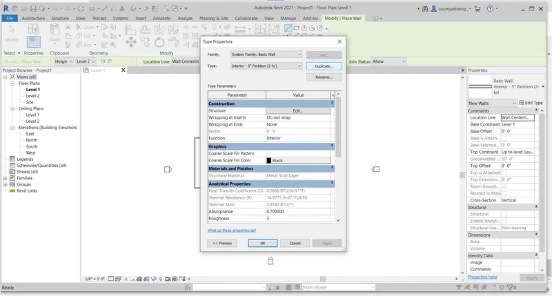
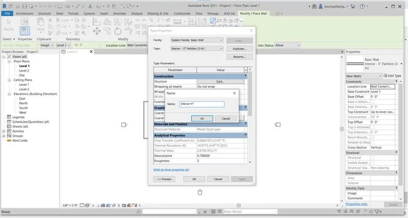
STEP-5: After selecting duplicate file a dialog box appears and make neccessary changes and click on ok
STEP-6:after creating duplicate file click on apply and choose ok
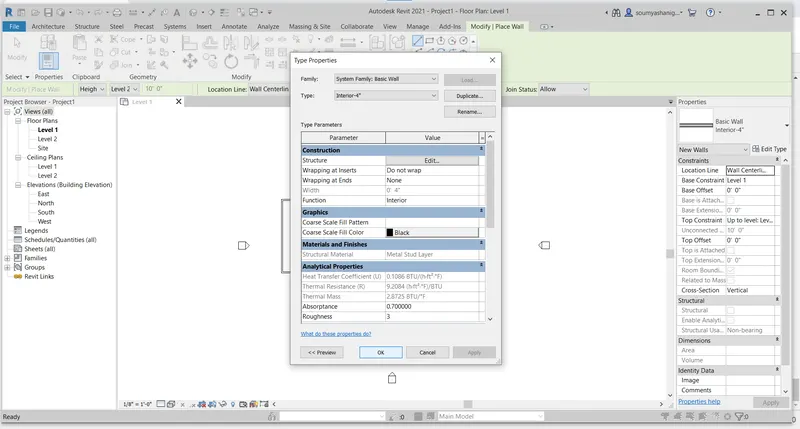
STEP-7:Now the required wall thickness is created and and now draw partion wall in required place in the layout
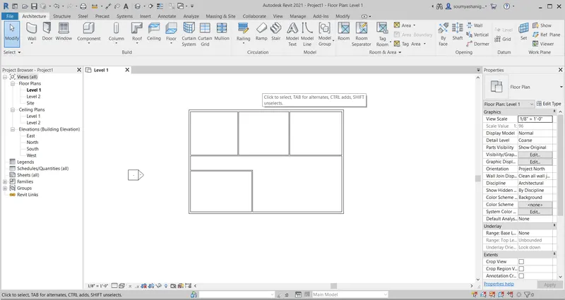
STEP-8:Now View the layout in 3D view by selecting view tab and choosing 3D view default option
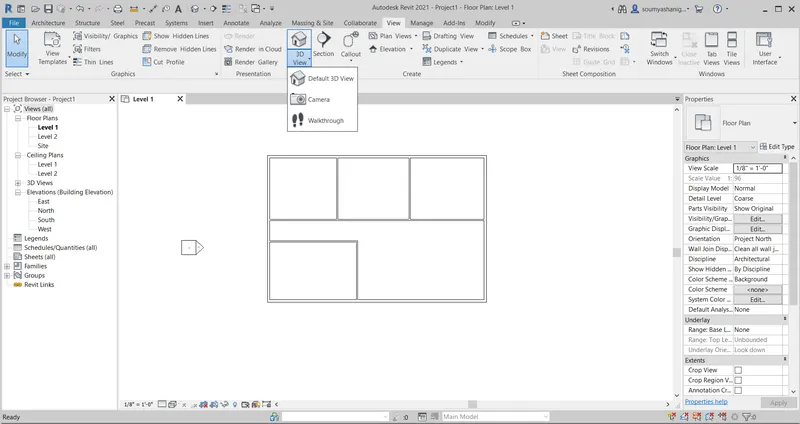
STEP-9: 3 D view is obtained and one can see the view in different view I.E realistic , shaded etc
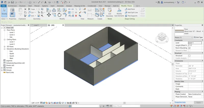
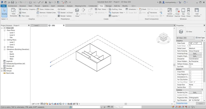
STEP-10:Now select the boundary wall then go to properties browser and select the required wall material i.e concrete light weight etc and click ok and select apply and chose ok
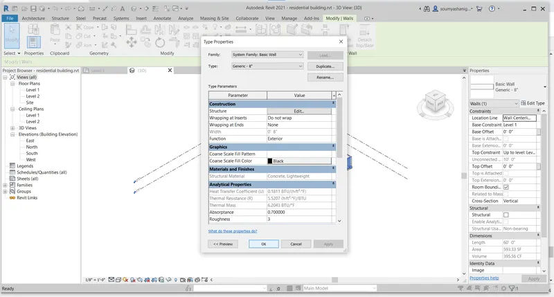
STEP-11:wall material and thickness are changed to concrete light weight material
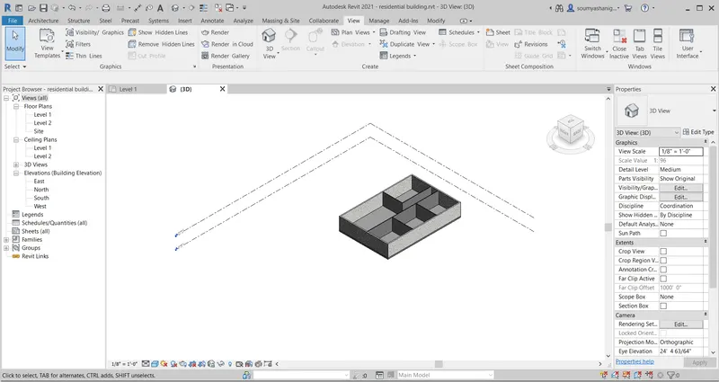
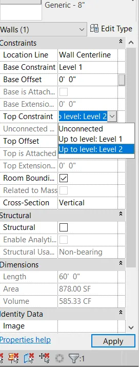
STEP-12: now select any boundary wall and Now go to properties browser and select top constraint and chose upto level-2 so the boundary wall will change the thickness of level-2 and do the same with remaining boundary wall
STEP-13:now the boundary walls and interior walls are constained
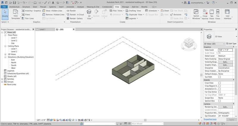
RESULT: The walls are cretaed in floor layout and wall thickness material are changed to required material by properties browser and levels are constrained by properties browser
a). Based on your observation, what is beneficial for connecting walls with associated levels rather than being Unconnected
ANS) Based on my observation, if heights of levels were modified then correspondily height of connected wall changes automatically this is benefits of connectind wall with asscociated levels
b.) Which option is convenient for modeling walls, By Height or By Depth?
ANS)Height is more convenient option for modelling walls rather than depth
3) Copy the model elements ( wall, floor ) modelled to Ground Floor Level and paste it aligned to First Floor Level . Use modify tab to utilize copy and paste options to align
elements to a different level
AIM: TO COPY THE MODEL ELEMENTS TO GROUND FLOOR LEVEL AND PASTE IT ALLIGNED TO FIRST FLOOR LEVEL AND USE MODIFY TAB TO UTILIZE COPY AND PASTE OPTIONS
TOOLS AND COMMANDS USED:
- Alligned
- Ground floor level
- Modify tab
- 3D View
PROCEDURE:
STEP-1:Open revit software and open previously created file
STEP-2:Now change the level 1 name to Groundfloorlevel so go to properties browser and double click on level-1 then change the level name to GROUNDFLOORLEVEL
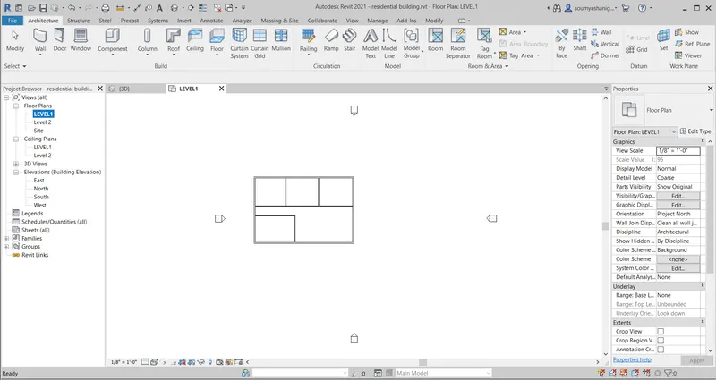
STEP-3:After changing name a dialog box appears then click on yes so that the name changes to GROUND floor level
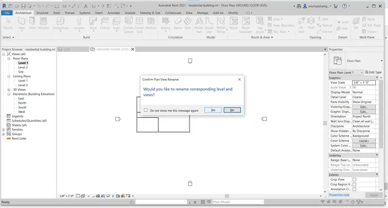
STEP-4:Now the level 1 is renamed to GROUND FLOOR LEVEL
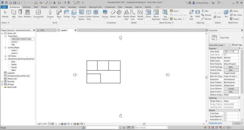
STEP-5:Now select the whole layout (or select modify tab) and and click on copy to clipboard option to copy the layout
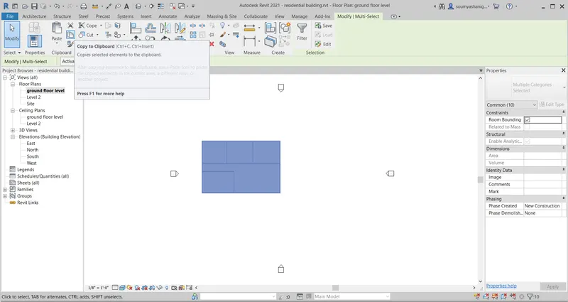
STEP-6:now the layout is copied to clipboard now click on the paste option ,and select alligned to select levels options
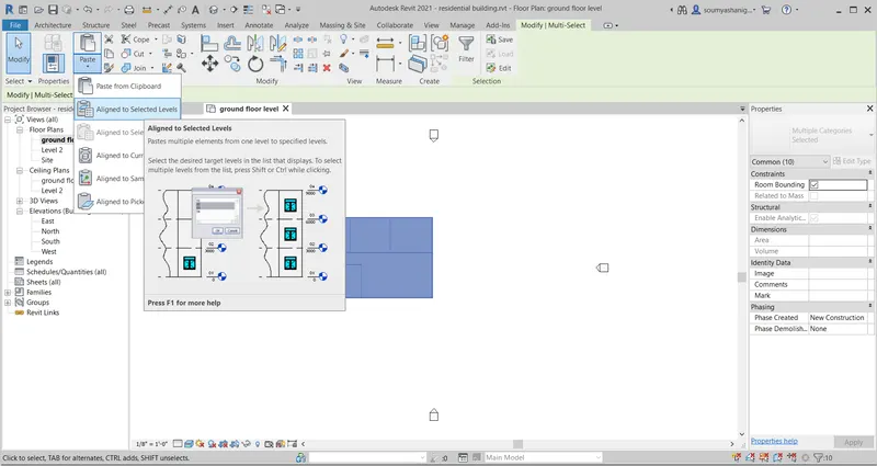
STEP-7:now click on that then a dialog box appears that with ground floor level and level-2 select level -2 option to copy the entire layout to level -2

STEP-8: Now click ok then the entire layout is created on level -2 also
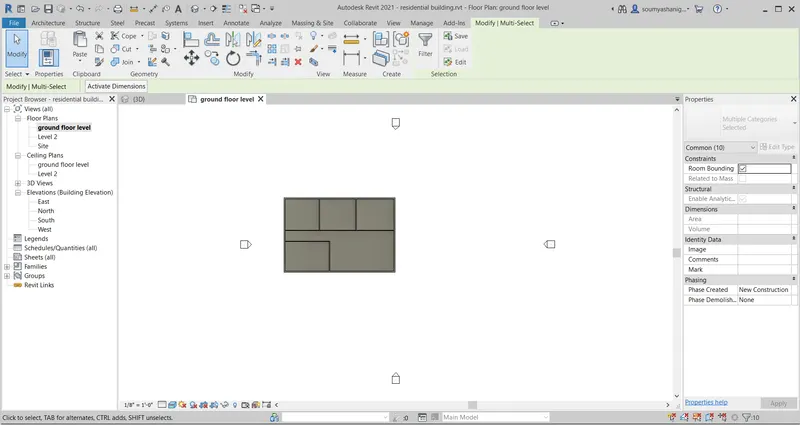
STEP-9: Now to see the layout is pasted in level-2 then view the layout in 3D view
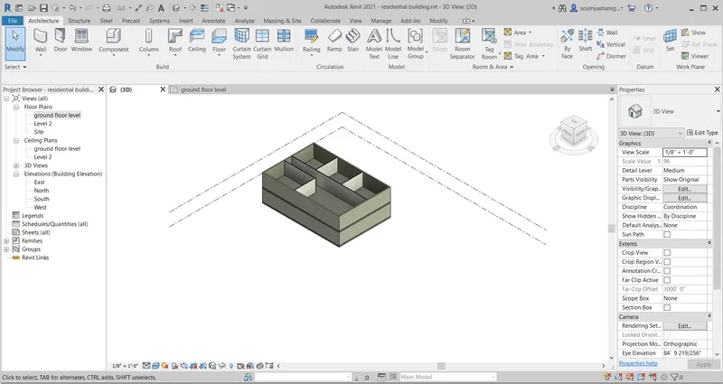
STEP-10:The layout is created in level 2
RESULT:The first floor level is created successfully by using copy and paste allign option and layout is viewed in 3 d view successfully
4) Use interior partition walls to create separate rooms within your residential unit. The model must include the following rooms
a. Living Room/ Drawing Room ( 15’ X 18’)
b. Dining Room (9’ X 11’)
c. Bed Room ( 9’ X 12’ and 15’ X 11’)
d. Rest Room ( 10’ X 12’ )
e. Kitchen (8’ X 10’)
The above are for examples. You can use them or use your measured entities to create your model based on your layout. You may include entry walkway, Patios or Guest
rooms based on your creativity and purpose of modeling. Convert units if you are using metric system
AIM: TO CREATE SEPERATE ROOM FOR LAYOUT BY USING INTERIOR PARTITION WALLS
TOOLS/COMMANDS USED:
- Interior walls
- Architectural tab
- Wall architectural
- Properties browser
PROCEDURE:
STEP-1:Open the REVIT software and click on new and select imperial architectural and click ok
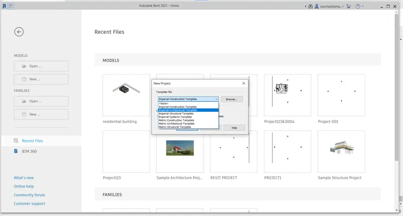
STEP-2:Now choose the architectural tab and select the wall architectural to create a new layout
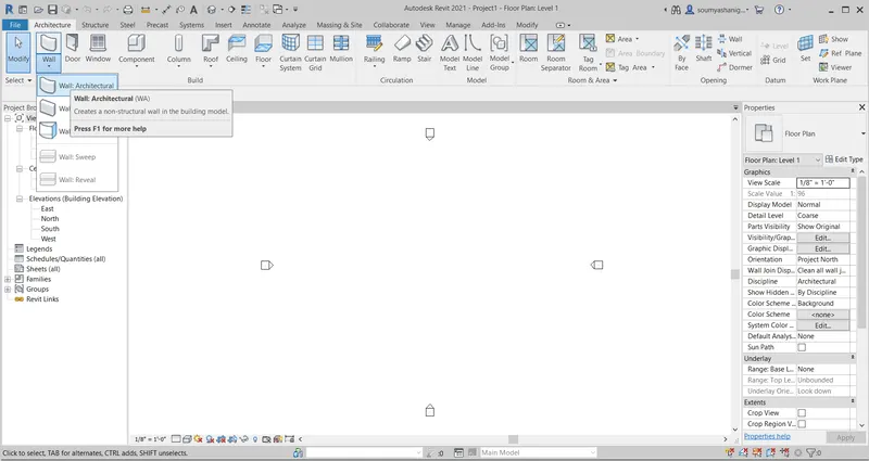
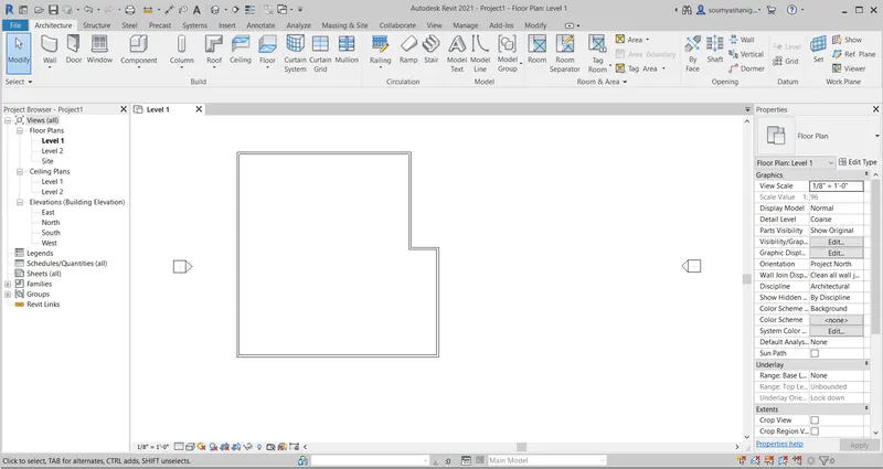
STEP-3:draw a layout of some dimensions with wall architectural tab
STEP-4:now go to properties browser and select the wall type and click on edit to change the thickness of the wall if necessary
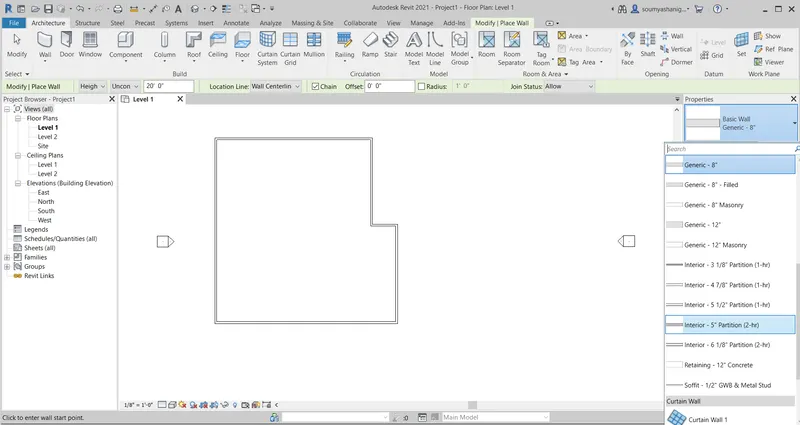
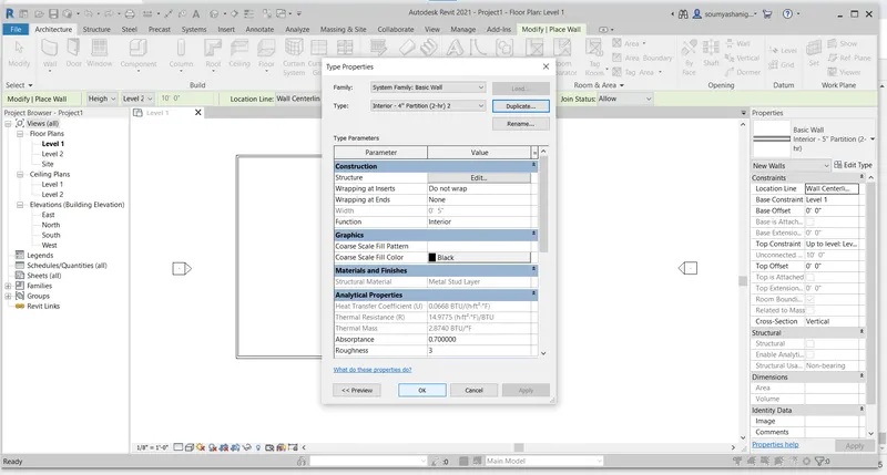
STEP-5:click ok and draw the interior partition walls
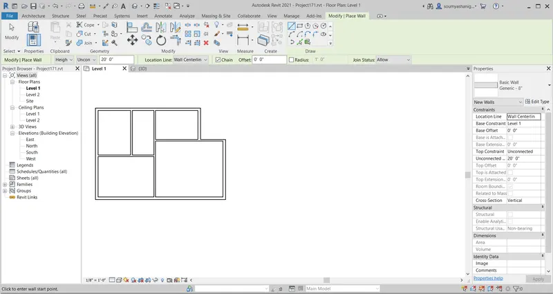
STEP-6:now select archtectural tab and click on door to draw the doors
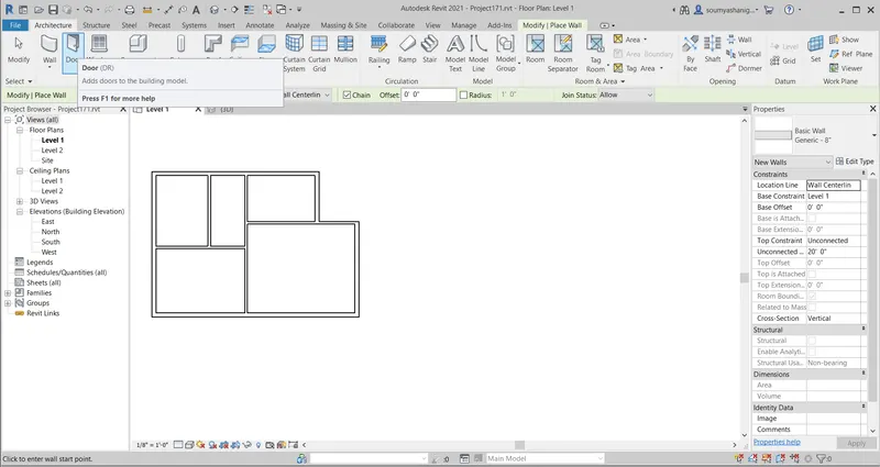
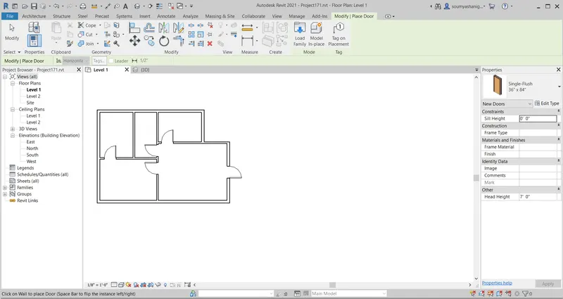
STEP-7: draw the doors as required place
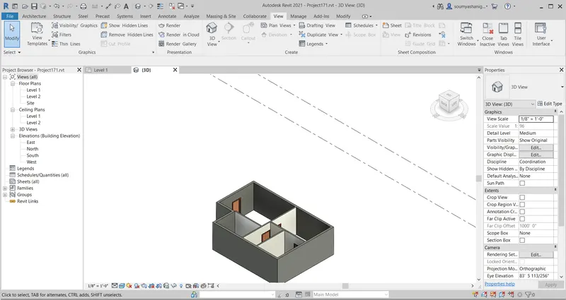
STEP-8:Now view the layout in 3 d view
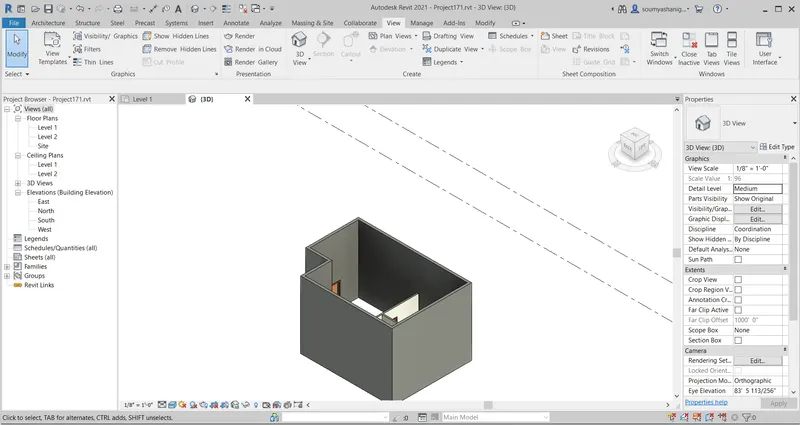
STEP-9: Now make levels equal by selecting any one boundary wall and chose constraint option from proprties browser and click to level-2 and click ok

STEP-10: DO same thing with all different wall to make all walls equal
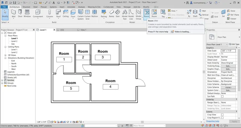
STEP-11: Select the room tab and select the room and place them according to our requirements
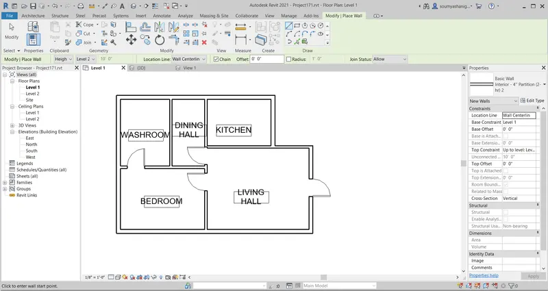
STEP-12: Now one can change the room name by editing the no 1,2,3,4,5 to living hall,dining hall,kitchen etc
STEP-13:view the layout in 3D view
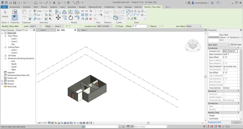
RESULT:The interior partition walls are created successfully for layout and named them by using room tab and viewed the layout in 3D V
5) Based on week 2 assignment, the components to be included in a residential unit were inserted to the Revit file. Place these components in appropriate locations to add details to your residential model
a. Place Doors and windows in the wall at appropriate locations
b. The Living Room must include furniture set, couch table and TV desk and shelf cabinets
c. The Dining Room must include a table and chairs serving the purpose of eating
d. Bed Room must include a bed set, shelf, lighting and individual study desk and chair
e. Rest room should include bath tub and plumbing fixtures discussed in class
f. Kitchen should include countertops, gas stove cabinet and shelves to store food items
g. The wash/storage room can include washing machines and shelves to store clothes
All the components are available in Revit Library. Use them to place at appropriate locations to add details to your model. Use 3D navigation to check the model and its authenticity on a real time basis to verify the model
AIM:TO ADD DIFFERENT COMPONENTS IN A RESIDENTIAL UNIT AND PLACE THEM IN APPROPRIATE LOCATION
TOOLS AND COMMANDS USED:
- DOORS
- WINDOWS
- FURNITURE SET
- TABLE
- ARCHITECTURAL TAB
PROCEDURE:
STEP-1:Open the previous created layout i.e of week-2
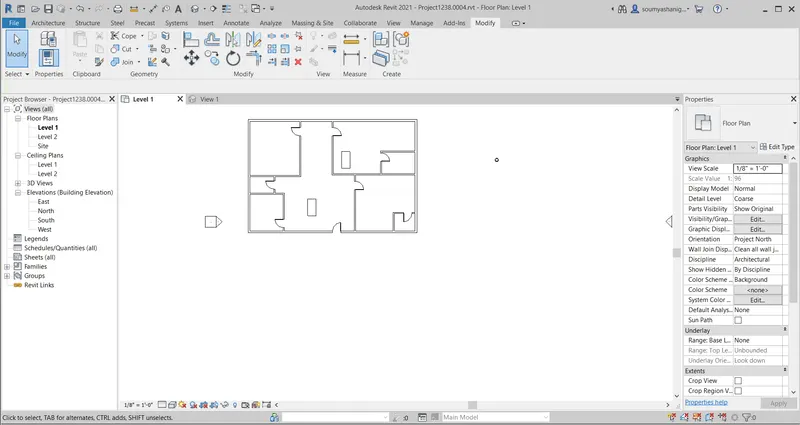
STEP-2: Now select architectural tab and click on windows tab and one can select the required dimensions of windows by selecting properties browser
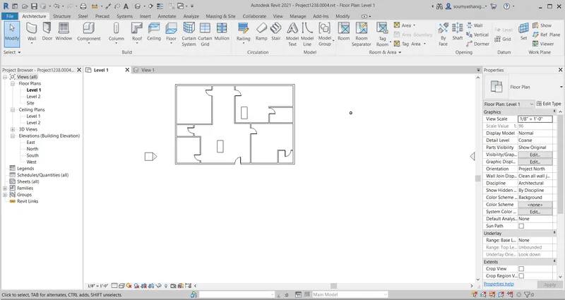
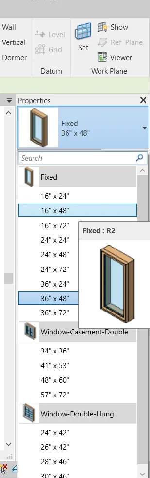
STEP-3: select the required window and now place the windows as required place
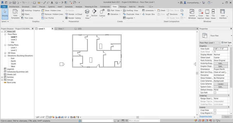
STEP-4: To view the windows in layout see the view in 3d view
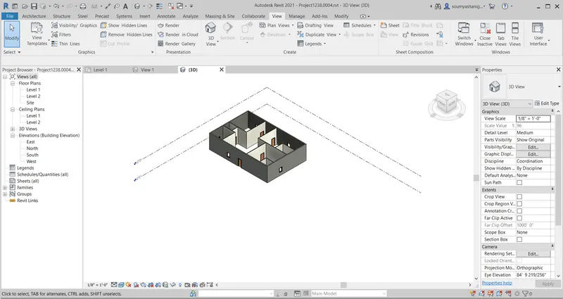
STEP-5: now to add different components to layout select archtectural tab and click on components and chose place a component
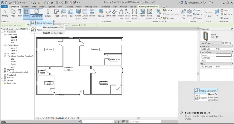
STEP-6:now go to propeties browser to select the required components to the layout
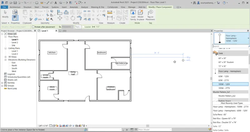
STEP-7:Select the table of required dimesions and palce them in appropriate place i.e living hall etc
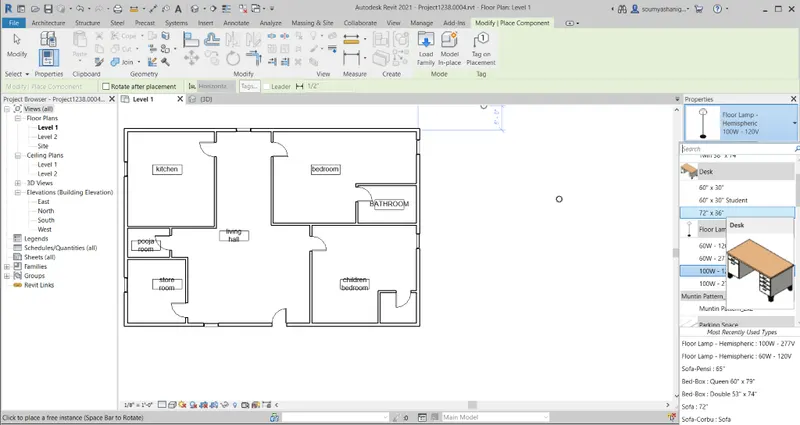
STEP-8: table is placed in living hall and bedroom
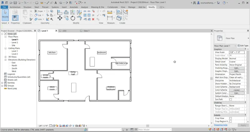
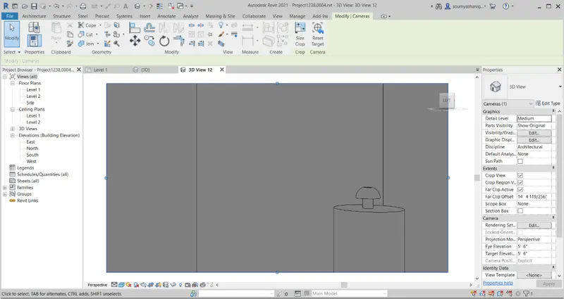
STEP-9: View the table in layout in camera option which is available from view option and select the 3d view
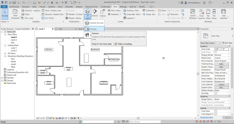
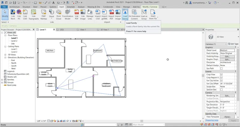
STEP-10: now put the camera at one end and select the components required to view
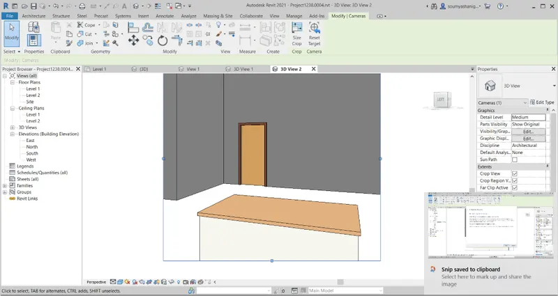
STEP-11:now the table is seen in 3d view
STEP-12: In the similar way add different components to the layout if particular component available then go to insert tab and click on load family
STEP-13:After selecting load family one can find many families available and choose anyone and click ok
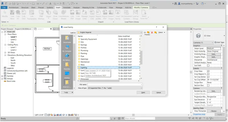
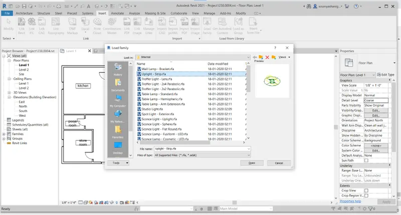
STEP-14:Now the component will be place in properties browser
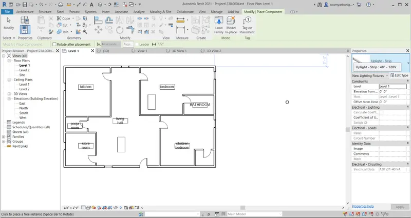
STEP-15:Now add different components like beds ,light ,tree,dining table ,sofas to the layout
KITCHEN COMPONENTS 3D VIEW
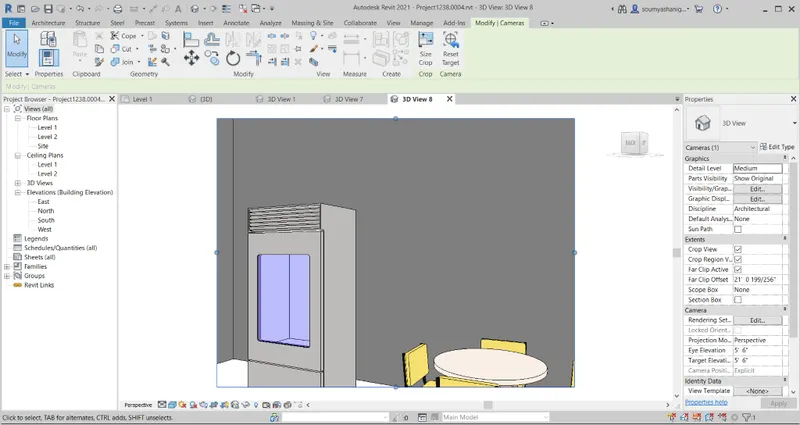
BEDROOM 3D VIEW BY CAMERA
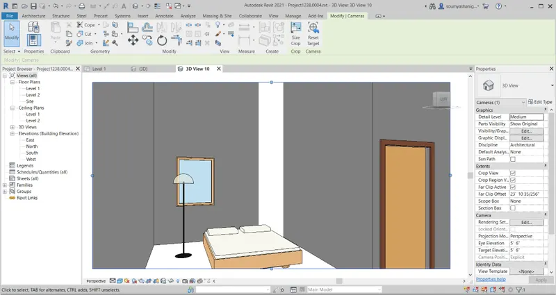
LIVING HALL COMPONENTS VISIBLE BY CAMERA
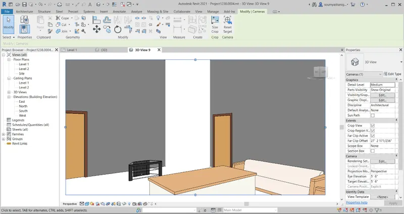
WASHROOM COMPONENTS VISIBLE BY CAMERA
STEP-12: Now view the layout in 3d view (shaded,realistic etc)
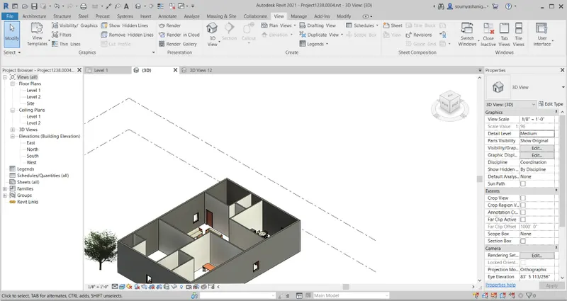
RESULT: the components are placed successfully in appropriate place and viewd them in 3d view by using camera and 3d view option