Introduction to REVIT
1)FROM THE FILE MENU,CREATE A NEW PROJECT(STRUCTURAL/ARCHITECTURAL/CONSTRUCTION TEMPLATE) AND NAME THE PROJECT APPROPRIATELY
AIM:
1)TO create a new project and name the project appropriately from the menu
TOOLS/COMMANDS USED:
- Mouse Wheel
- Properties palette
- File Menu
- Open
PROCEDURE:
STEP 1: First open revit software
STEP2: Now click on file option which is at top left corner.
STEP-3:Next select on new option
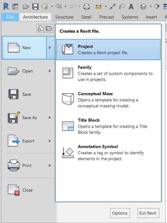
STEP 4:Now select project option.
STEP 5:After selecting project a dialog box of new project appears.Click the drop box under template file and select the template required for project
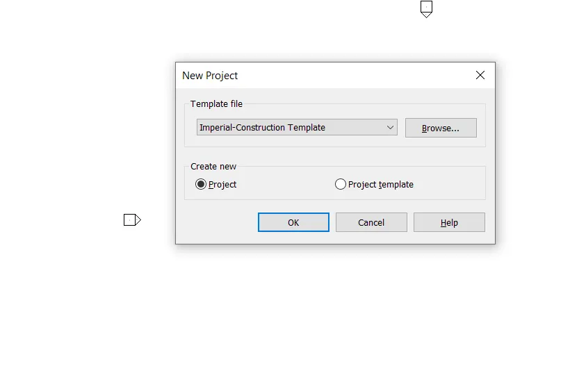
STEP 6:Click ok
STEP-7: A new project name is created
STEP-8:Now go to properties palatte and select the view option and name the project as PROJECT-1.
STEP-9: Click apply
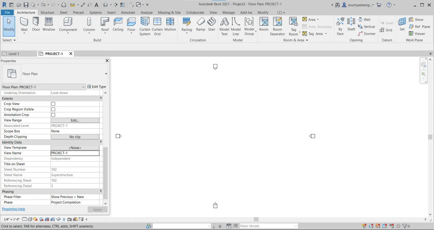
STEP-10:File name is named as PROJECT-1
STEP-11:Follow similar method for architectural template and construction template and name them as required.
RESULT :
New project (structural/architectural/structural template)is created successfully by above procedure and named architectural template as PROJECT-1 through view name in name palette.
2)SAVE THE NEW PROJECT FILE.CLOSE AND OPEN USING ICONS FROM FILE TOOLBAR
AIM:
To save the new project file,close and open the new project file
COMMANDS AND TOOLS USED:
- MOUSE WHEEL
- FILE MENU
- SAVE
- NEW PROJECT
PROCEDURE:
STEP-1:Select the file tool which is at the top left corner.
STEP-2:click on save option.
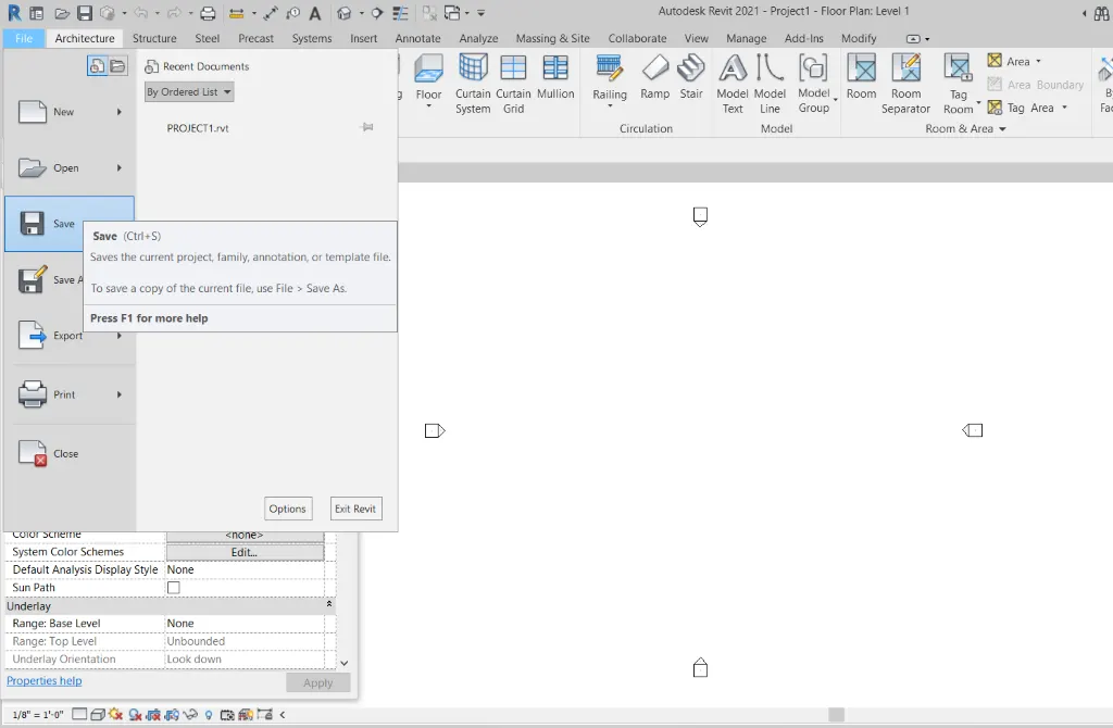
STEP-3:Specify the place where to save and name the project as REVIT PROJECT and save the project.
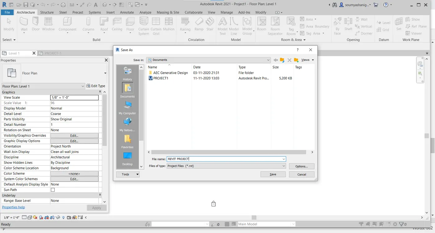
STEP-4 A new project is saved as REVIT PROJECT in specified place
STEP-5:NOW select file tab click on open then open project
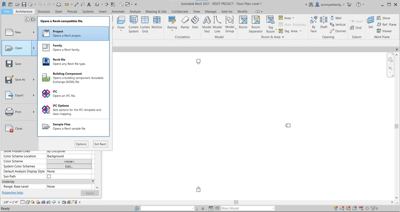
STEP-6: Select REVIT PROJECT and open the file.
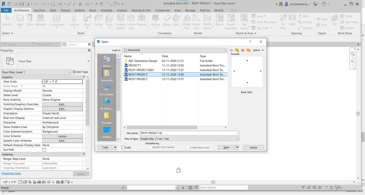
STEP-7: Close the revit project.
RESULT:
New project is created successfully and saved in desktop through file tools and it is opened and closed as required
3)FROM THE ARCHITECTURE/STRUCTURE TOOL BAR FAMILIARIZE WITH OPTIONS TO DRAW A WALL,CREATE A RECTANGULAR LAYOUT OF WALLS OF ABOUT 40'-0''X35'-0''
AIM: TO DRAW A ARCHITECTURE/STRUCTURAL RECTANGULAR LAYOUT WALLS OF ABOUT 40'-0''X35'-0''.
TOOLS/COMMENTS USED:
- WALL
- ARCHITECTURE
PROCEDURE:
STEP-1:Select wall icon and click on wall architectural.
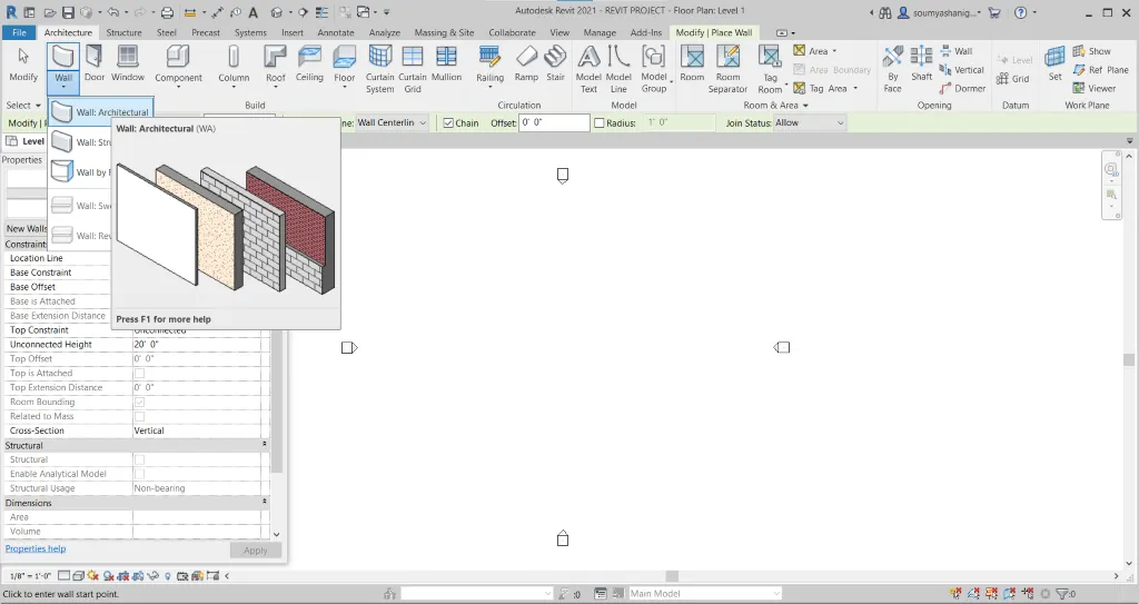
STEP-2:Then draw rectangualar layout of 40'-0'' X35'-0'' in such a way that draw a line of 40'-0'' along X-axis press enter and move cursor along Y-Axisa and draw a line of 35'-0'' press enter and then move cursor along X-Axis of 40'-0'' press enter then along Y-Axis of 35'-0'' press enter.
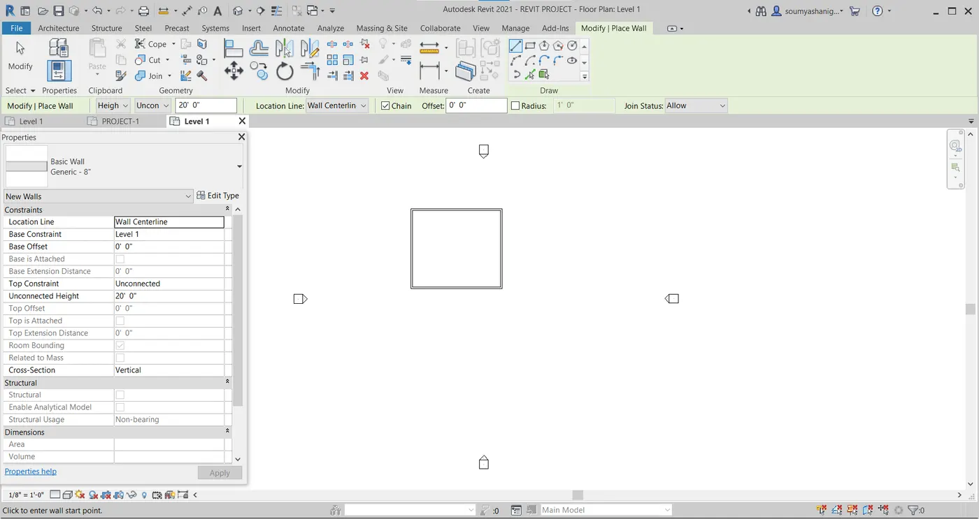
RESULT:A rectangular layout wall of 40'-0''X35'-0'' was created successfully with the help of wall tool
4.FROM ANNOTATE TOOL BAR USE ALLIGNED OPTION TO ADD DIMENSIONS TO THE LAYOUT
AIM:TO ADD DIMENSIONS TO THE LAYOUT BY USING ALIGNED OPTION FROM ANNOTATE TOOL BAR.
TOOLS/COMMANDS USED:
- ANNOTATE TOOL BAR
- ALLIGNED
PROCEDURE:
- STEP-1:Choose Annotate Tab
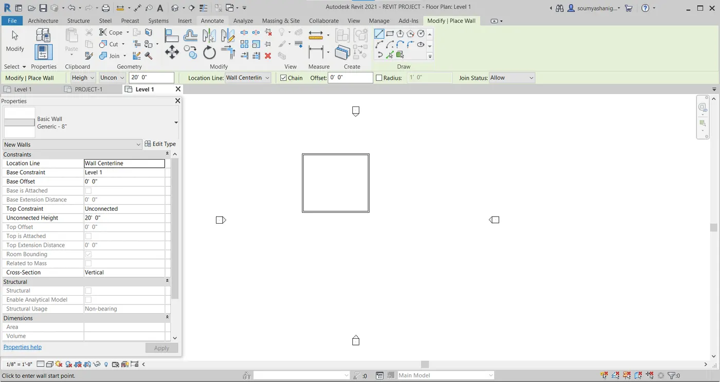
- STEP-2:click on alligned option
STEP-3:select the wall end from one end to another end then click enter.
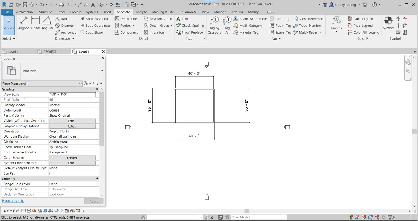
RESULT: Dimensions were added to the layout successfully by using alligned option from annotate tool bar
5)USE THE PROPERTIES BROWSER TO SWITCH TO DIFFERENT WALL TYPES
AIM:To switch to different wall types by use of properties browser
TOOLS/COMMANDS USED:
- PROPERTIES BROWSER
PROCEDURE
STEP-1: Select a rectangualr layout wall
STEP-2: Click on properties browser where one can different wall types.
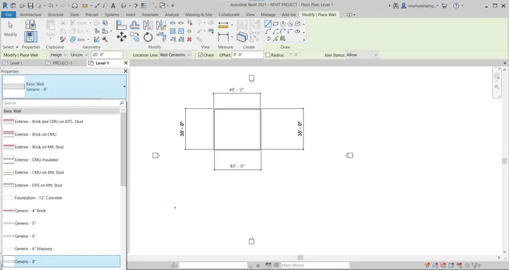
Step-4: click on required wall type
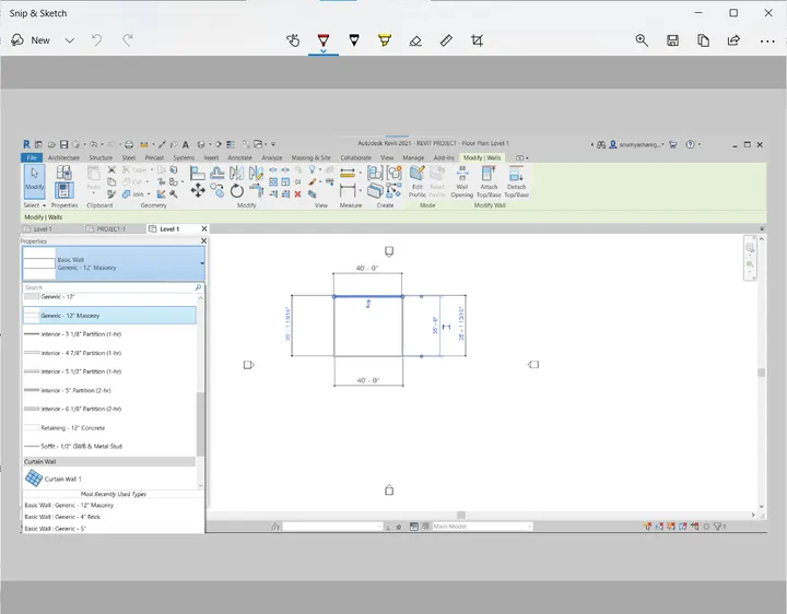
RESULT:Wall type is successfully changed from Genric-8'' to 12''-Mansory view by propeties browser.
6)CREATE A 3D VIEW FROM THE VIEW TOOL BAR AND SAVE THE VIEW WITH APPROPRIATE NAME
AIM:TO CREATE THE 3D VIEW OF LAYOUT AND SAVE THEM WITH APPROPRIATE NAME.
TOOLS/COMMENTS USED:
- VIEW TOOL BAR
- PROPERTIES PALATTE
- 3D VIEW
- DEFUALT 3D VIEW
PROCEDURE:
STEP-1:Create a model
STEP-2:Select View toolbar
STEP-3:Select 3D VIEW and choose DEFAULT 3D VIEW option
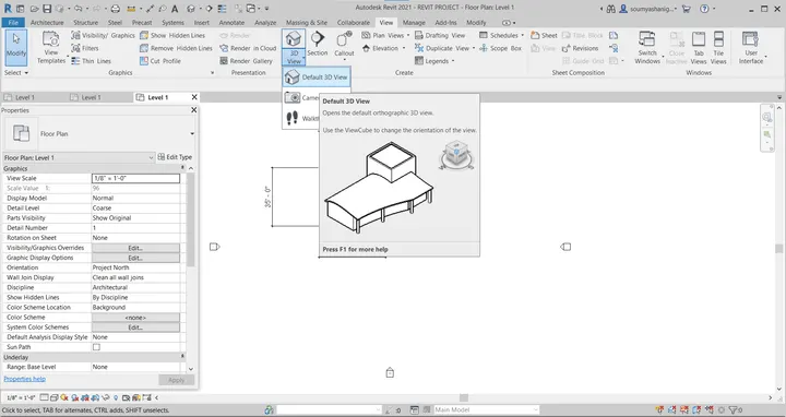
STEP-3:3D view of model is obtained
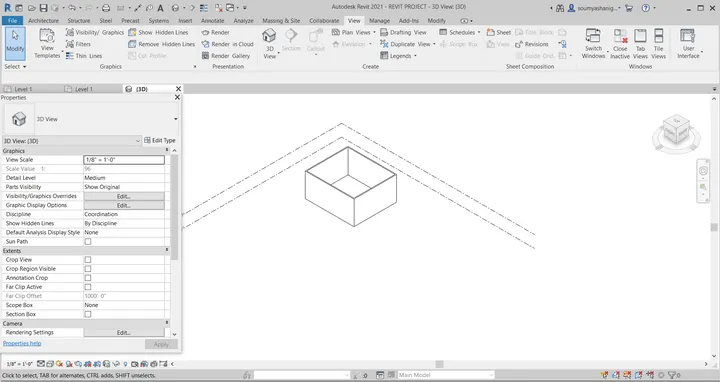
STEP-4: now click on properties palete and select the view name.
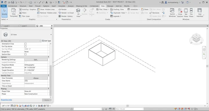
STEP-5:now change the view name as required.Name the view as 3D VIEW-1
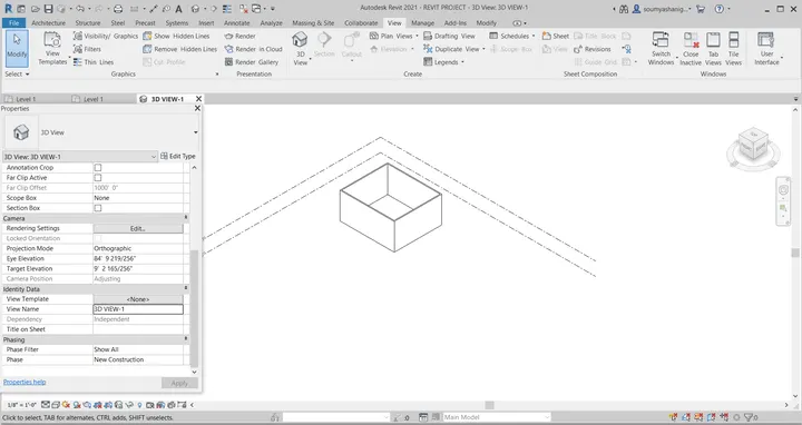
STEP-5:click on apply then the view name has changed to 3D VIEW-1.
RESULT:3D VIEW is created successfully and name has changed to 3D VIEW-1 by view bar
7)NAVIGATE THROUGH THE 3D MODEL USING VIEW CUBE.ORBIT/PAN THROUGH THE MODEL LAYOUT CREATED
AIM:TO NAVIGATE THE 3D MODEL BY USING VIEW CUBE
TOOLS/COMMANDS USED:
- VIEW
- ORBIT
- NAVIGATE BAR
- PAN
PROCEDURE:
STEP-1:Create a model
STEP-2:Click on view bar then select 3D VIEW option and click on DEFAULT 3D VIEW option
STEP-3:Click on navigation wheel and select the require view to display
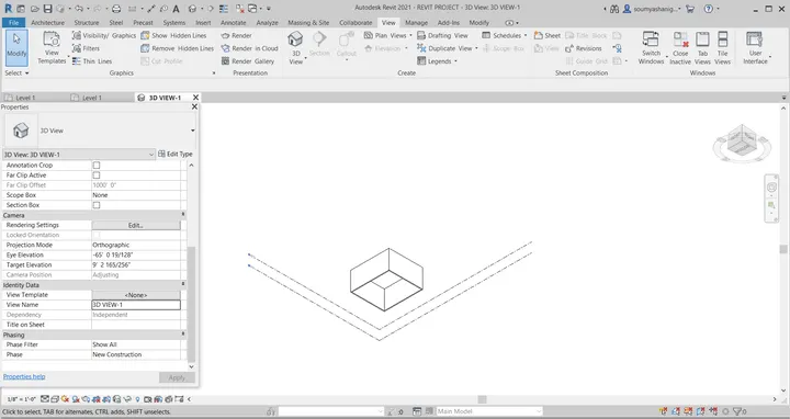
STEP-4:In a similar way one change the required view to display
STEP-5:Now select the orbit option to change the pivot point
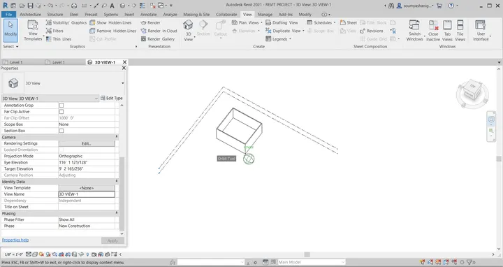
STEP-6: now select the tab option to view the model in 3D VIEW in 360 degrees.
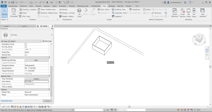
RESULT:Navigation of 3D VIEW is successfully created.
8) USE THE VISIBILITY SETTINGS OPTIONS BELOW TO SWITCH MODEL TO SHADED,REALISTIC,HIDDEN LINES OPTIONS
AIM:TO SWITCH THE MODEL TO SHADED ,RELISTIC,HIDDEN LINES BY VISIBILITY SETTINGS OPTION
TOOLS/COMMANDS USED:
- VISIBILITY OPTIONS
PROCEDURE:
STEP-1:Create 3D model
STEP-2:Select the visibility option which is available in bottom line
STEP-3:After Clicking on visibility options one can find many options like shaded,realistic,hidden etc
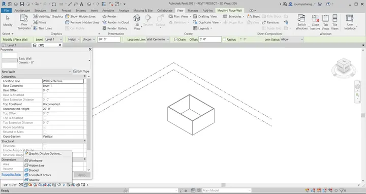
STEP-4:Chose the required options to change the shade of model
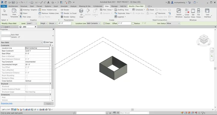
STEP-5: The model is changed to realistic shade. In similar way one can change to shaded,hidden shade of model
RESULT:The model is successfully changed to realistic shade by graphic dispaly option
9)TURN THE SUNLIGHT ON AND OFF TO VIEW SHADINGS IN THE LAYOUT CREATED
AIM:TO TURN SUNLIGHT ON AND OFF TO VIEW SHADINGS
TOOLS AND COMMANDS USED:
- MANAGE TOOL BAR
- ADDITIONAL SETTINGS
- SUN SETTINGS
PROCEDURE:
STEP-1:Create a 3D model view
STEP-2:Chose manage tool bar and click on additional settings option and select sun settings
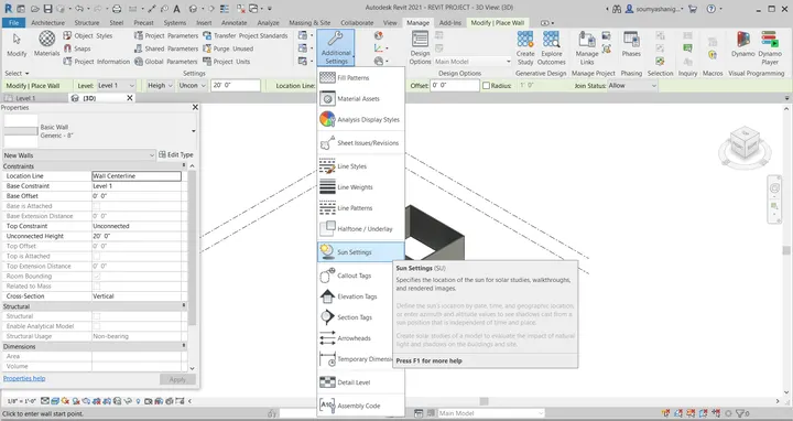
STEP-3: after clicking on sun settings a dialog box appears on screen
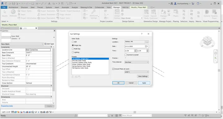
STEP-4: Fill the require details and select apply and click ok
STEP-5:Now click on sunsettings option which is on bottom line
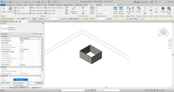
STEP-6:click on sun path on to view sun shade
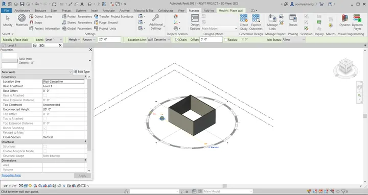
STEP-7:Click on sunpath off to off the view of sunshade
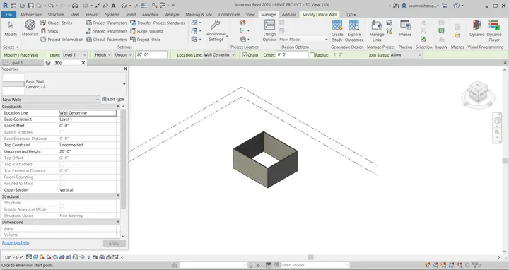
RESULT:The layout is successfully turned off and turned on the sunlight
10)USE THE MANAGE TOOL BAR TO ENTER PROJECT SETTINGS,PROJECT NAME,AND PROJECT ISSUE DATE(CHOOSE ACCORDING TO YOUR CONVENIENCE)
AIM:TO ENTER PROJECT NAME ,PROJECT SETTINGS,AND PROJECT ISSUE DATE BY USE OF MANAGE TOOL BAR
TOOLS/COMMANDS USED:
- MANAGE TOOL BAR
- PROJECT INFORMATION
PROCEDURE:
STEP-1:create a 3D MODEL
STEP-2:Click on manage tool bar and select project information then a dialog appears on the screen

STEP-3: Fill the required details in the dialog box and click ok
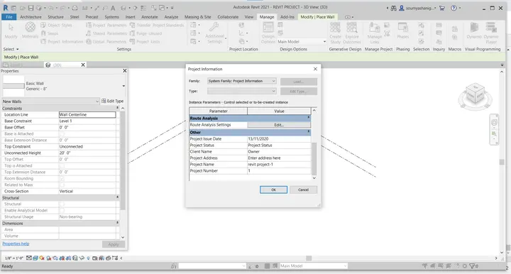
RESULT:Project settings, project name,and project issue date has successfully entered in dialog box by use of project information bar
11) WHAT IS ANALYZE TOOL BAR USED IN REVIT? HOW IT IS BENEFICIAL FOR DESIGN AND MODELING
- Analyze tool bar is used to analyze the entire structural project.It also help in load combinations,Boundary conditions,cases adjustments etc
- It helps in energy analysis or energy optimization of building
- It evaluates and generate sustainability of the structure so one can change develop necessary changes in project.
- It also helps in managing cooling and heating loads.
- There are many options available in this analyze tool bar as shown in figure below

12)WHAT ARE THE LINKS THAT REVIT SUPPORTS TO BE LINKED TO THE MODEL
- LINK REVIT: Link one revit model to current revit model or another revit model
- LINK CAD:Link 2D plan to revit file then converts to 3D model by using 3D dimesions
- LINK IFC:Links an IFC file to current project for information that is required for additional design work
- LINK TOPOGRAPHY: Links the existing topography to present revit model
- MANAGE LINKS:It link Revit Cad files to current working project
- LINK IMAGE:Link an image for the current working project
- DWF MARKUP:Links DWF files into Revit project
- POINT CLOUD:Links Point cloud project into current project
- COORDINATION MODEL:Links a NWD or NWC file to provide context for the Revit model

- 13)WHY DO YOU COLLABORATE TAB IN REVIT? HOW IT SUPPORTS MODELLING AND EFFICIENCY
- Collaborate tab is one where team members or group of people can create multiple projects,these members are not only inside network but also outside network
- This makes one to create more projects in less time.
- Under this Collaborate tab we have many options like to show past work ,Coordination Review etc

- Efficiency of the work can be increased as more no of people work on same project,this makes to take less time to complete project .