REVIT_3D Rendering of a House plan_Project 1
Based on the project saved from Week 3, proceed from First Floor Level .Model a Ceiling from architecture tab above the walls at first floor level
AIM:TO MODEL A CEILING FROM ARCHITECTURE TAB ABOVE THE WALLS AT FIRST FLOOR LEVEL
TOOLS AND COMMANDS USED:
- ARCHITECTURAL TAB
- SAVE
- OPEN
- CEILING
- PROJEC T BROWSER
PROCEDURE:
STEP-1:open the revit software and open previous week layout which is saved in the revit
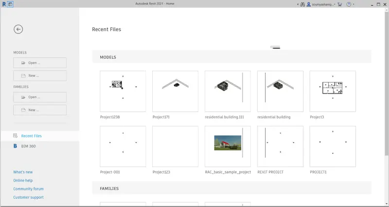
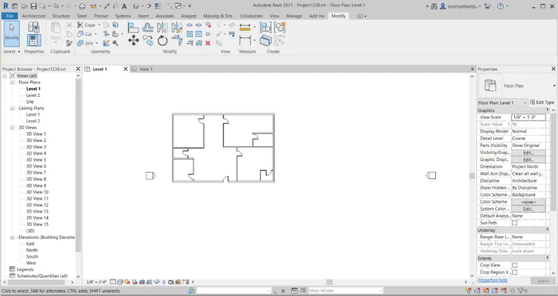
STEP-2:open the project1238 and the file will be open
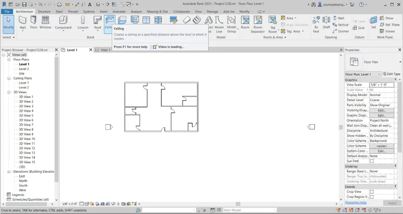
STEP-3: Now go to architectural tab and choose ceiling option
STEP-4: Before selecting ceiling option now go to propeties palette and change the level to first floor level
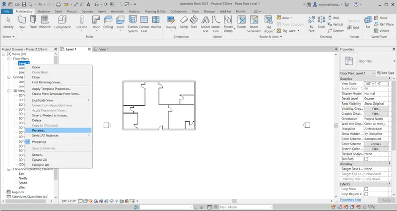
STEP-5:Now a dialog box appears then click ok now the name has changed to first floor level
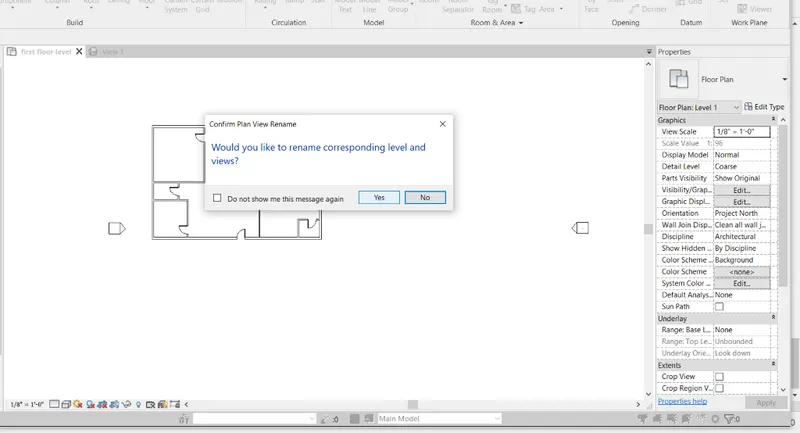
STEP-6: now select ceiling option then there will two options available i.e:
AUTOMATICALLY CEILING: THIS CREATES THE CEILING AUTOMATICALLY
SKETCH CEILING : THIS IS ONE WHERE ONE HAS TO CREATE
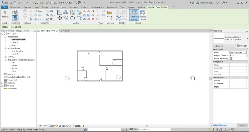
STEP-7:Now select the SKETCH CEILING which is more effiecient to work

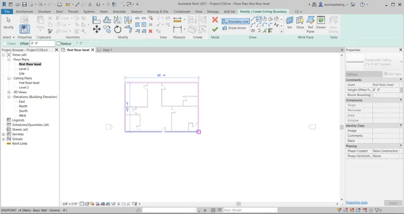
STEP-8:Now screen appears in this way
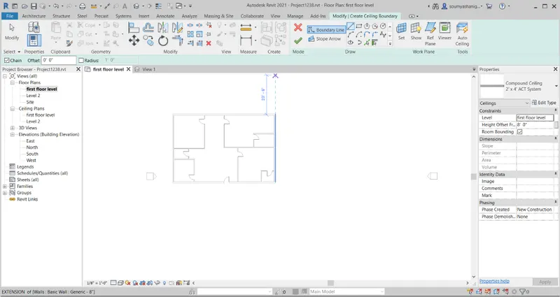
STEP-9: Now select the entire boundary or layout by chosing rectangular option
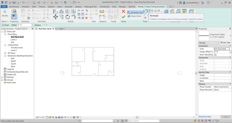
STEP-10:Now the layout is selected and click on right mark which is on mode option
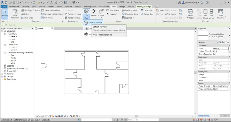
STEP-11:Now t he layout has ceiling which will be seen in 3d view ( Go to view tab and click on 3D view and choose default 3D VIEW)

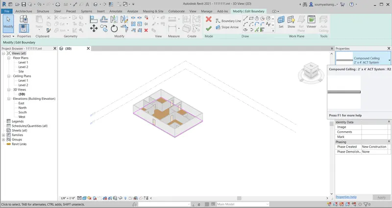
STEP-11:Now go to properties browser to change the type of ceiling materaial select the ceiling boundary and click on ceiling material
STEP-12: One can edit the thickness and create a duplicate file and click on apply
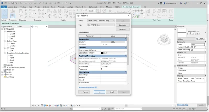
STEP-13:Now one can change the thickness and material of ceiling . now the newly ceiling material
RESULT:Ceiling is added to the layout successfully and the layout is viewed in 3 D VIEW
2) Model a roof above the ceiling by selecting the footprints of ceiling. Using the adjustment tool bars appearing on screen adjust the roof slope to 10 degrees
AIM:TO CREATE A ROOF ABOVE THE CEILING BY SELECTING THE FOOTPRINTS OF CEILING WITH ROOF SLOPE TO 10 DEGREES
TOOLS AND COMMANDS USED:
- ARCHITECTURE
- ROOF
- ROOF BY FOOTPRINT
- MODE
- SLOPE
PROCEDURE:
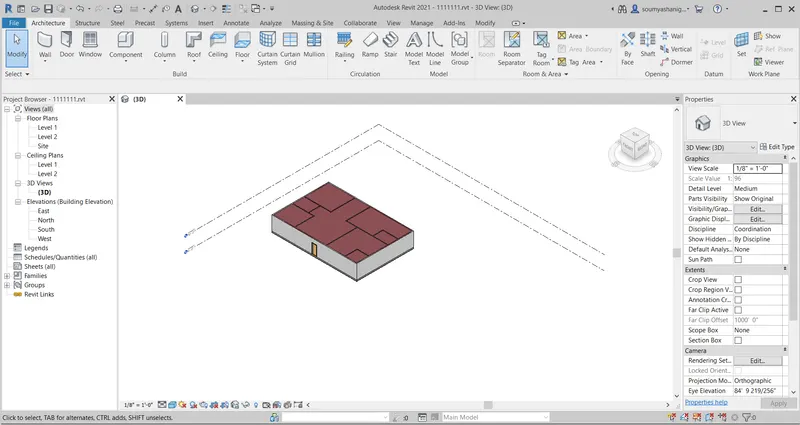
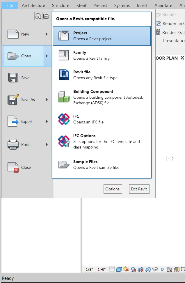
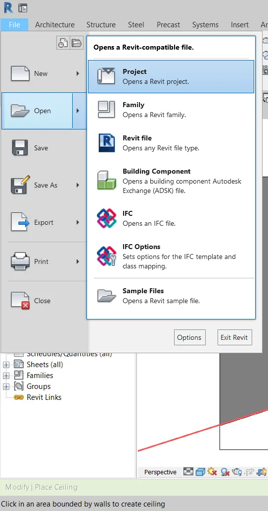
STEP-1:First go to file ortion and click on open option to open the existing project created in previous question
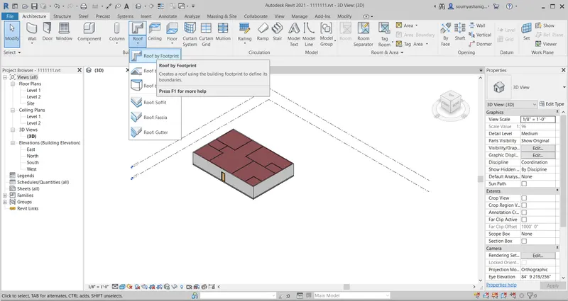
STEP-2: Go to architectural tab and click on roof option and choose roof by footprint method
STEP-3:After choosing this a dialog box appears for selecting the level to which is to be created
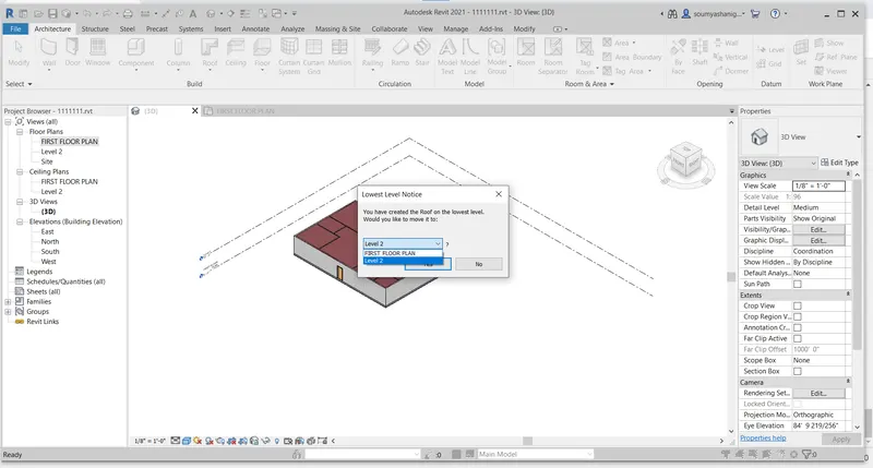
STEP-4:Click on yes and now select boundaries of the layout and choose picklines option
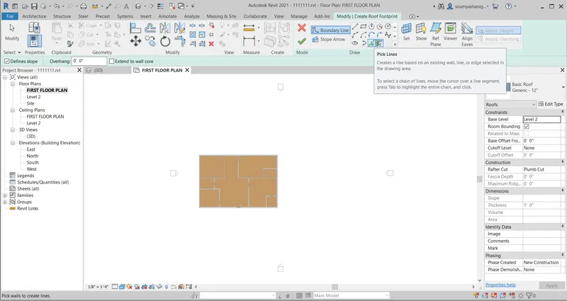
STEP-5:Chose the layout boundary and click on mode correct option
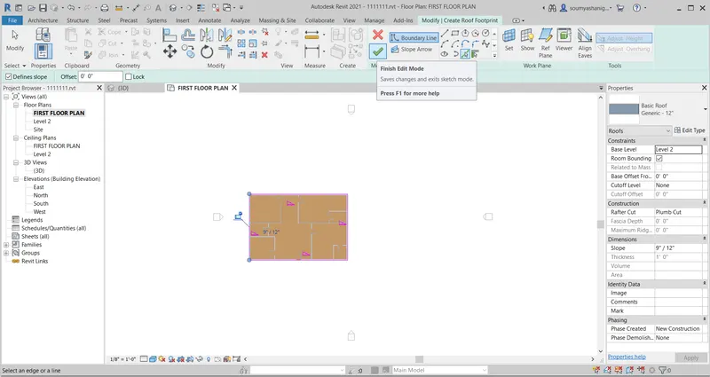
STEP-6: Now the layout will be selected
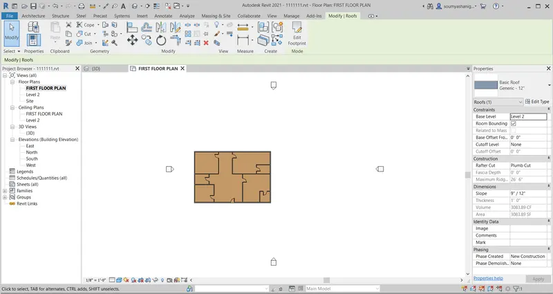
STEP-7:To view the roof select the 3 D VIEW TO VIEW THE roof created
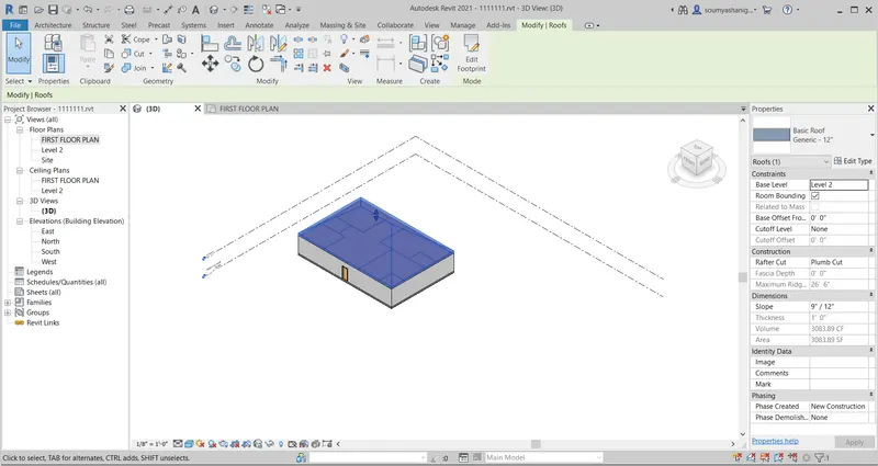
STEP-8: select the roof and Now go to propeties browser and select the material of roof required
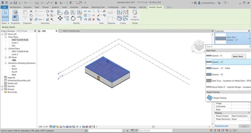
STEP-9:Select the slope as 10 degrees and select the required material and click ok so the material thickness and slope has changed
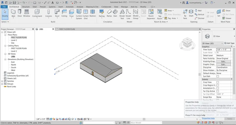
RESULT:The roof material has attached to the layout by Roof sloping option succesfully the roof is adjusted to a slope of 10 degrees
3) Using the file saved from week 2 to 4, create plan views for ground floor level and first floor level including all the walls , floors and components. Separate them to
architecture and structural plans
a. Architecture plan must have walls , floors and all the components placed within the buildingb. Structure plan must have details of only walls, floors and columns
b. Structure plan must have details of only walls, floors and columns
AIM:To create plan view for ground level and first floor level and to seperate architecture and structural plans
TOOLS AND COMMANDS USED:
- FILE
- OPEN
- ARCHITECTURAL
- PLAN VIEW
- STRUCTURAL PLAN
- ARCHITECTURAL PLAN
A)PROCEDURE:
STEP-1:open the file option and choose open option and select existing file
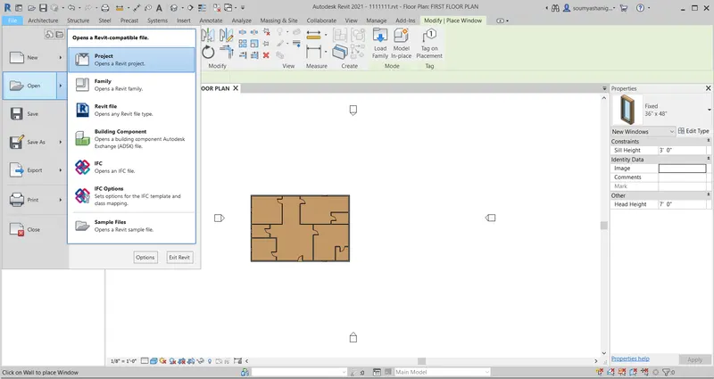
STEP-2:Go to view toolbar and select plan views
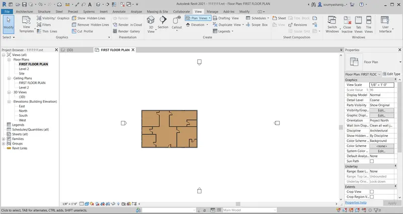
STEP-3:Select the architectural planview which consists of walls floor and windows
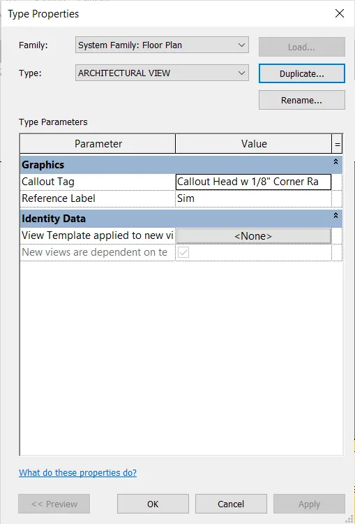
CLICK OK THEN THE VIEW HAS CHANGED TO ARCHITECTURAL VIEW
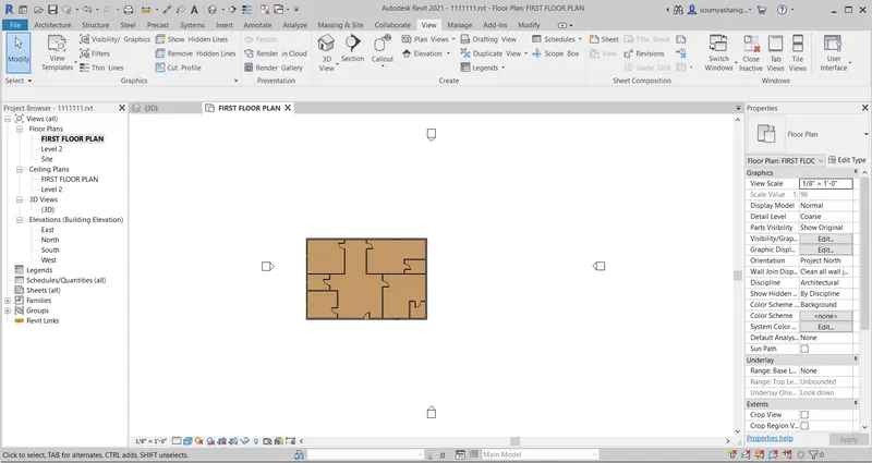
RESULT: the layout are viewed and architectural plan view successfully by the view tab
B)PROCEDURE
STEP-1: now same go to view tab and select PLAN VIEW optionand select the structural view
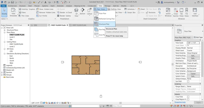
STEP-2: After clicking the view will be changed to structural view
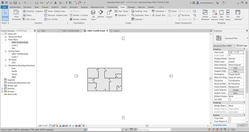
RESULT: the layout are viewed and structural plan view successfully by the view tab
4) Using annotate tool bar add dimensions to all the walls and floors with reference to the longitudinal and transverse grids created in the project file
a. The architecture plan dimensions include details on where the components are placed within the buildings with relation to grids. Overall dimensions are sufficient for architecture plans
b. The Structure plan dimensions must include details on position of all the walls and interior walls with reference to grids. Locate all the framing components of the building with reference to a fixed point using Structural plans
AIM:TO ADD DIMENSIONS OF ALL THE WALLS,COLUMNS AND OTHER COMPONENTS WITH REFERENCE TO THE GRIDS
TOOLS AND COMMANDS USED:
- ARCHITECTURAL
- GRIDS
- ANNOTATE
- DIMENSIONS
- ALLIGNED DIMENSIONS
- FILE
PROCEDURE:
STEP-1:Open the file created previously by choosing file option and click on open then open the previous created file
STEP-2:Now select architectural tab and click on grids
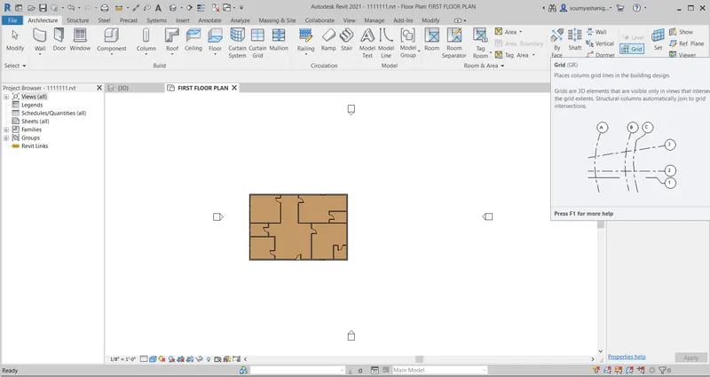
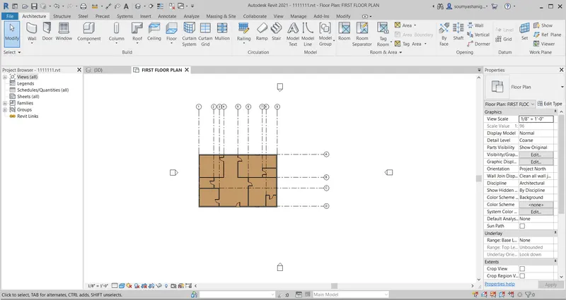
STEP-3: After selecting draw longitudinal and traverse grids and name them as required i.e ( lonitudinal _1,2,3 etc and traverse -a,b etc or viceversa)
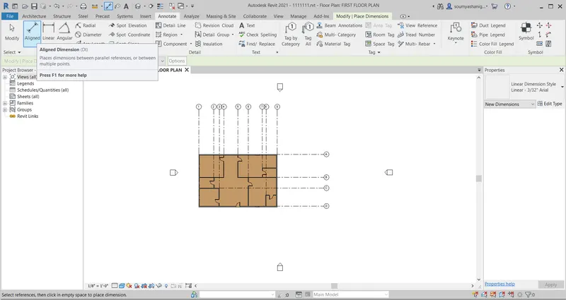
STEP-4:Now go to annotate tab and chose allign dimensions
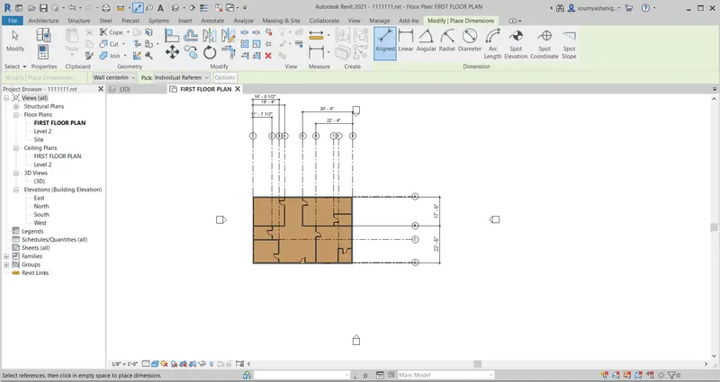
STEP-5: now mark dimensions in a required place
STEP-6: repeat the same process with stuctural plan view
RESULT: THE DIMENSIONS WERE SUCCESSFULLY ADDED TO THE LAYOUT BY USING GRIDS
5) Create a sheet template from the view tab and adjust the parameters on the sheet to add appropriate views
AIM: TO CREATE A SHEET TEMPLATE FROM VIEW TAB AND TO ADJUST THE PARAMETERS ON THE SHEET
TOOLS AND COMMANDS USED:
- VIEW
- SHEET
- OK
- FILE
- OPEN
PROCEDURE:
STEP-1:open the previously created file by clicking file option and select open then it open the existing file
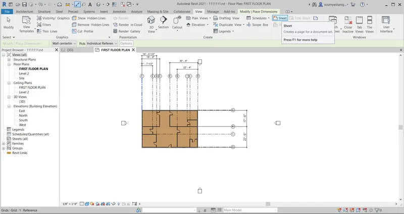
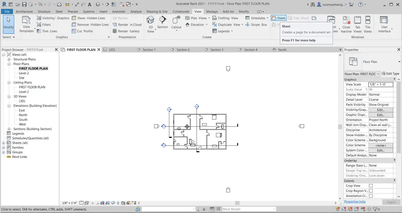
STEP-2:now click on view tab and click on sheet option
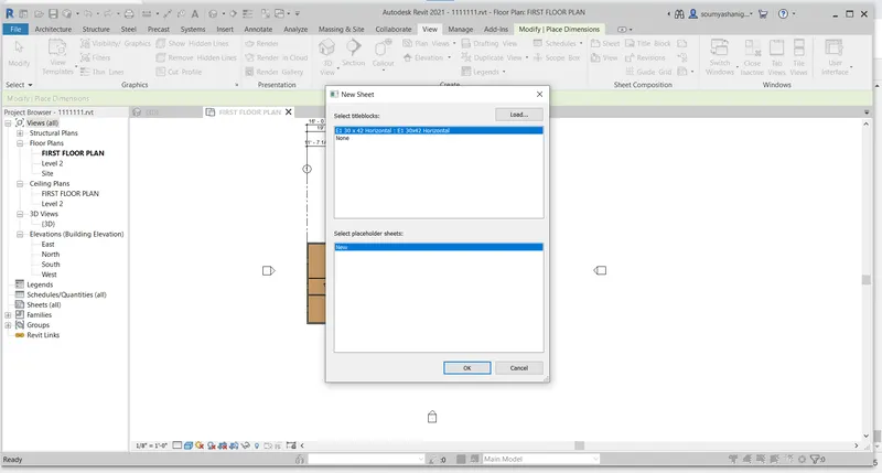
STEP-3:Now click on sheet option then a dialog box appears which gives an option to select the dimensions of the sheet ( to require any more dimensions sheet use load option so one can find many shhets and choose one and click OPEN
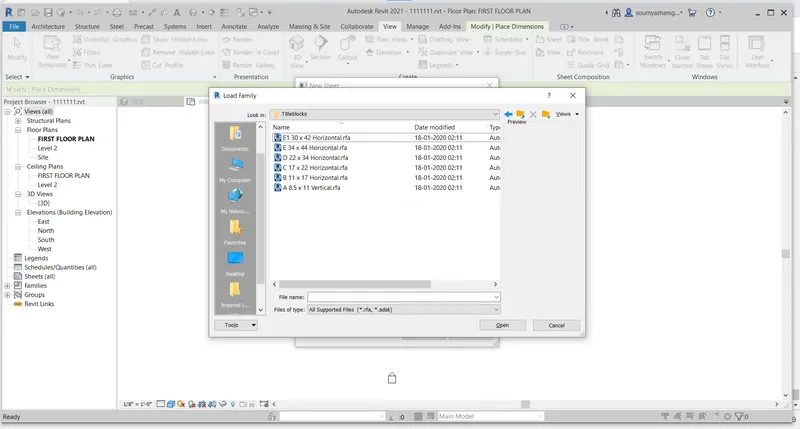
STEP-4: After loading sheets one can available many options select one sheet from that
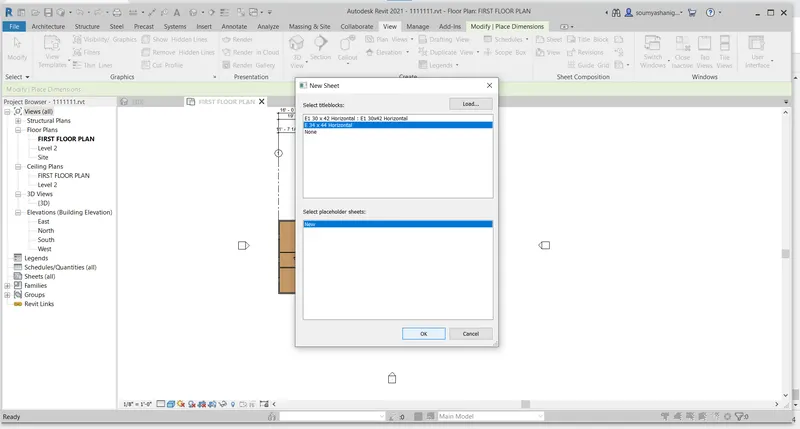
STEP-5:NOW CLICK OK THEN A SHEET IS VISIBLE ON THE SCREEN
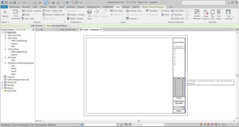
STEP-6: NOW one can make necessary chnages like project name and sheet name,issue date etc inthe sheet by double clicking on a particular previous cretaed name etc
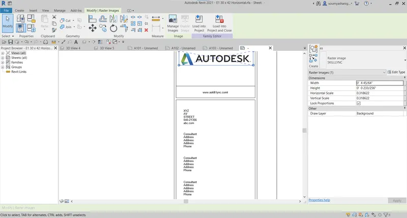
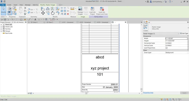
ENTIRE SHEET:
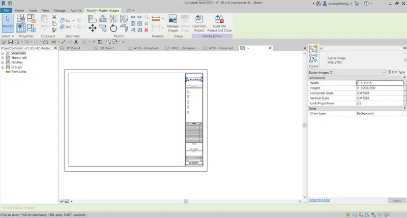
STEP-7: One can attach th views to the sheet also
RESULT: THE sheet is created successfully and details of the project like name ,issue date etc has successfully filled in the sheet
6)Using the elevation tab create the elevation views, looking at your building from East, North, South and West
AIM: TO CREATE ELEVATION VIEWS OF LAYOUT FROM EAST ,NORTH,SOUTH,WEST BY USING ELEVATION TAB
TOOLS AND COMMANDS USED:
- ELEVATION
- VIEW
- EAST
- NORTH
- SOUTH
- WEST
PROCEDURE :
STEP-1:OPEN THE REVIT SOFTWARE and open file and click on open and chose the existing file
STEP-2:Now go to view tab and choose elevation bar
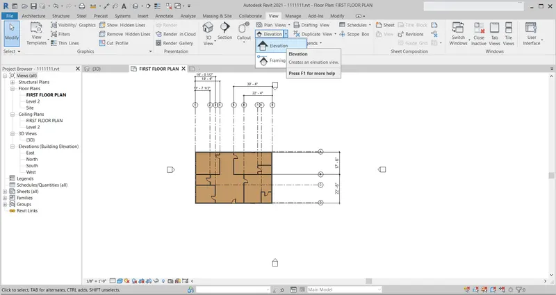
(or) go to properties browser and choose elevations
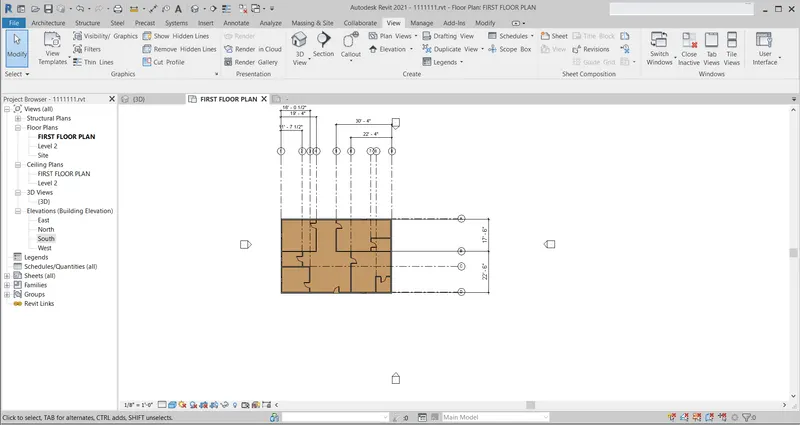
STEP-3: Now choose the required direction to open
EAST:
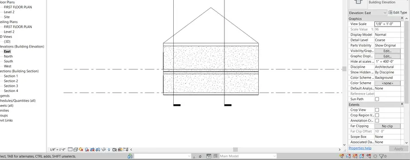
NORTH:
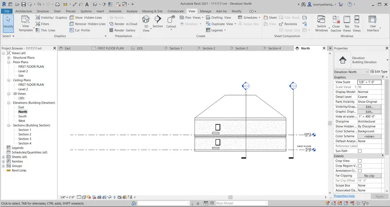
SOUTH:
WEST:
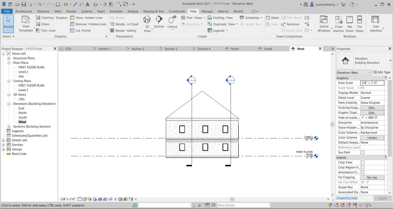
RESULT: The elevation view of the layout were successfully viewed by the elevation tab
7) Produce section cut through each room either cutting across longitudinally or in a transverse direction
AIM:TO PRODUCE SECTION CUT THROUGH EACH ROOM EITHER CUTTING ACROSS LONGITUDINALY OR IN A TRANSVERSE DIRECTION
TOOLS AND COMMANDS USED:
- VIEW
- SECTION
- FILE
- OPEN
PROCEDURE:
STEP-1:open revit software and open the file choose open then open the previously created layout

STEP-2:go to view tab and select section view option
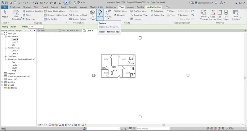
STEP-3:seelect the sections to view i.e longitudinal sections and traverse sections ( i selected 2 traverse and longitudinal sections) by draging line one can move above or below
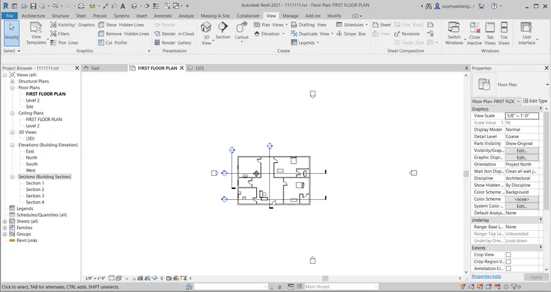
STEP-4: to view the section go to properties browser and select sections then different sections will be shown
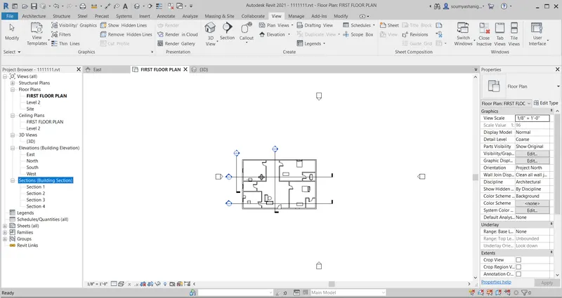
STEP-5:Select the view to display
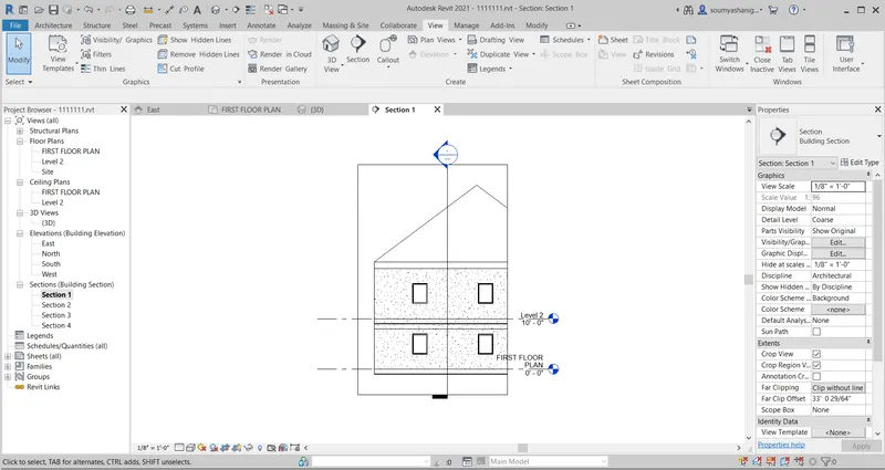
SECTION-1:
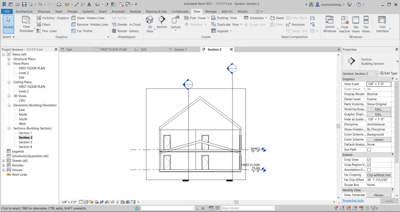
SECTION-2:
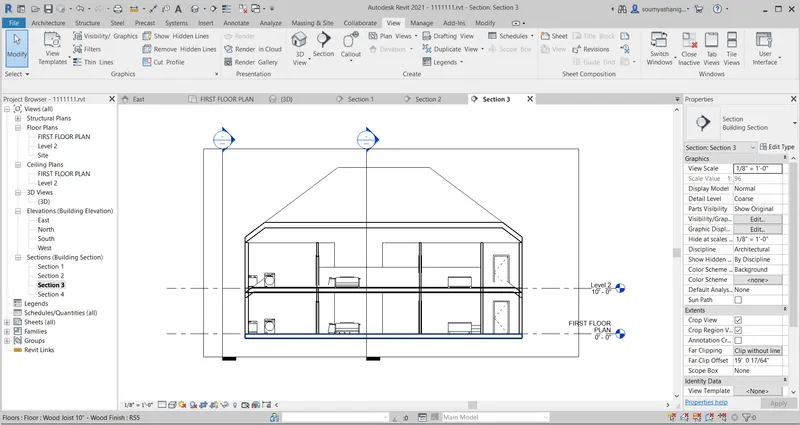
SECTION-3:
SECTION-4:
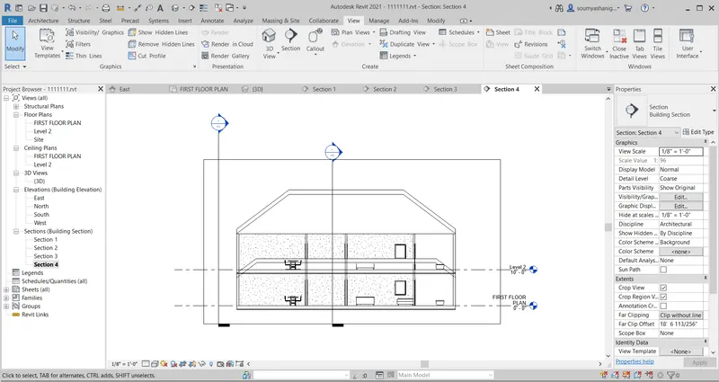
RESULT: The layout are viewed succesfuuly in different section views
8) Classify the views , Plan Views, Section Views and Elevation views to either Design or Documentation category using Properties browser
AIM:TO CLASSIFY THE VIEWS,PLAN VIEWS,SECTION VIEWS AND ELEVATION VIEW TO EITHER DESIGN OR DOCUMENTATION CATEGORY USING PROPETIES BROWSER
TOOLS AND COMMANDS USED:
- VIEW
- PLAN VIEW
- SECTION VIEW
- SHEET
- ELEVATION VIEW
PROCEDURE:
STEP-1:Open the revit software and open file and select open and open previously created file
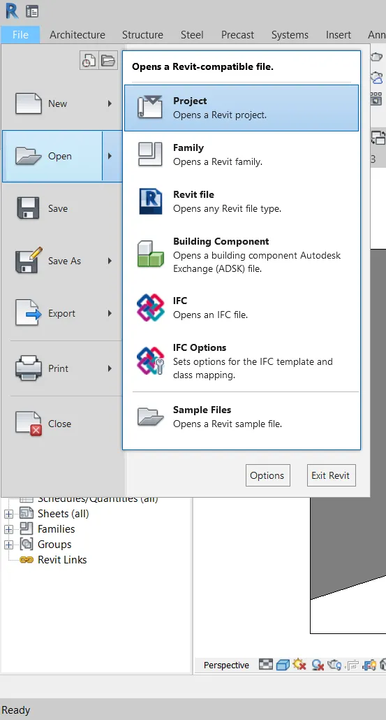
STEP-2:go to view tab select the sheet option to create a new sheet
STEP-3: A dialog box appears then choose the required sheet
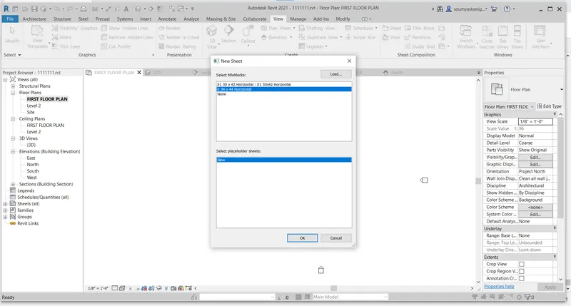
STEP-4: click ok then a sheet appears
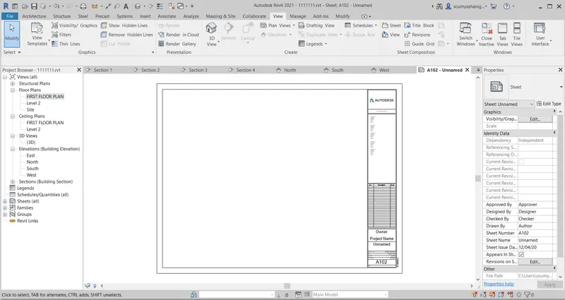
STEP-5:Then change the required names or add details to it
STEP-6:Now go to view tab and select the view option
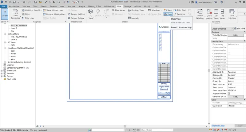
STEP-7: a dialog box appears then select the required view to be place in the sheet
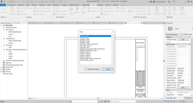
STEP-8:Then select the views to place in the sheet
SOUTH AND EAST VIEW ARE PLACED IN SHEET
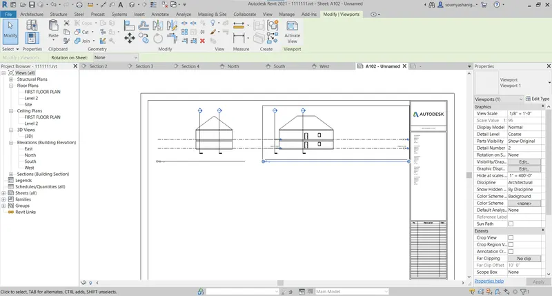
IN A SIMILAR ONE CAN ADD ALL VIEWS IN THE SHEET
ALL SECTION VIEW AND DIRECTIONS:
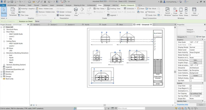
ALL VIEWS :
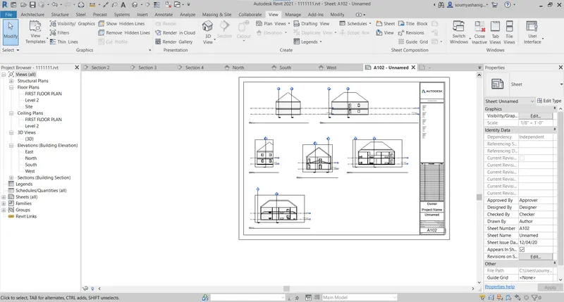
STEP-9: ALL VIEWS CAN BE PLACED IN SHEET BY SELECTING LARGER DIMENSIONS OF SHEET
RESULT:ALL VIEWS ,SECTION VIEW ETC ARE SUCCESSFULLY PLACED IN
9) Using the sheet template produced create multiple sheets as follows
a. A 101 – Ground Floor Architecture Plan
b. A 102- First Floor Architecture Plan
c. A 103- Roof Plan
d. S 101- Ground Floor Structural Plan
e. S 102 – First Floor Structural Plan
f. S 103- Roof Framing Plan
g. A-201 – North South Elevations
h. A-202- East West Elevations
Add additional sheets based on the sections created in your revit file
AIM:TO CREATE MULTIPLE SHEETS BY USING VIEW TAB
TOOLS AND COMMANDS USED:
- view
- sheet
- different plan
PROCEDURE:
STEP-1:Open revit software and open file and select the open and open the previously created file
STEP-2:Go to view tab and select sheet
STEP-3:Then a dialog box appears to select the required sheet
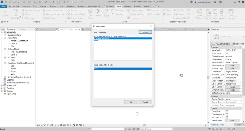
STEP-4:Click ok then sheet appears on the screen
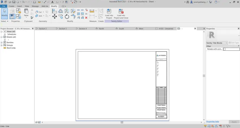
STEP-5: One can make changes the details in the sheet like mail address etc
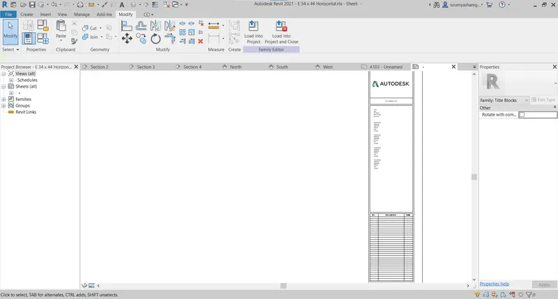
STEP-6:Now go to view tab and select the view
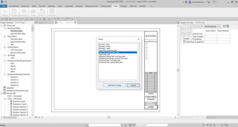
STEP-7 one can add different views to the sheet
GROUND FLOOR ARCHITECTURAL VIEW
AFTER ADD TO SHEET THEN IT APPERAS TO
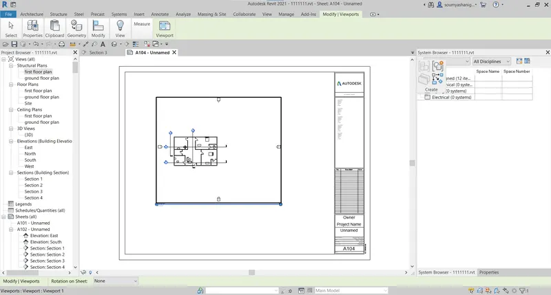
now do same process go to view tab and select sheet and add views to it for all view same process exists
FIRST FLOOR PLAN VIEW
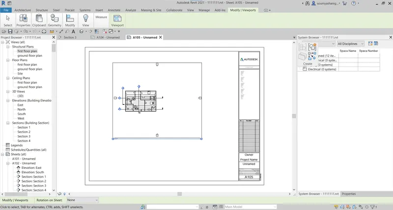
ROOF PLAN:
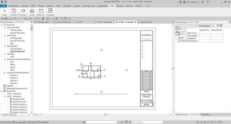
GROUND FLOOR STRUCTURAL VIEW
FIRST FLOOR STRUCTURAL VIEW
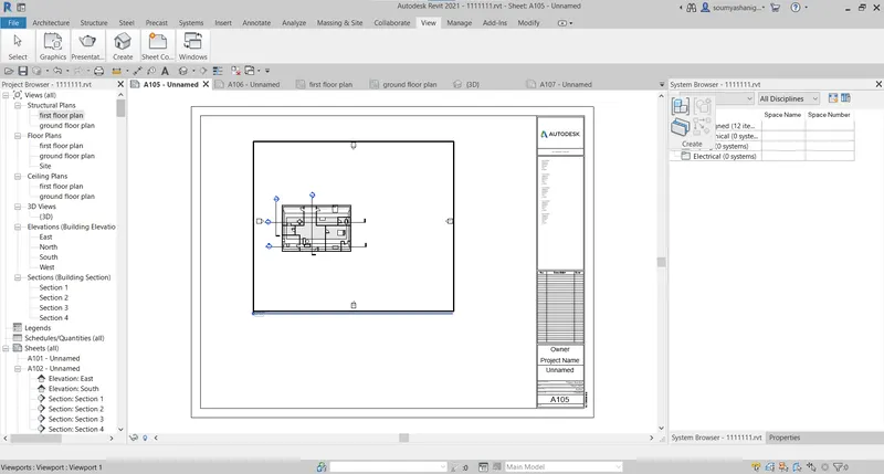
ROOF FRAMING PLAN:
NORTH SOUTH ELEVATIONS
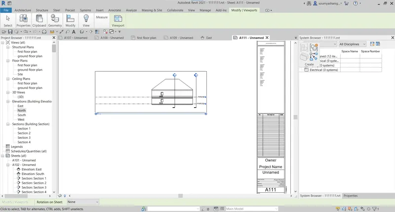
EAST WEST ELEVATIONS
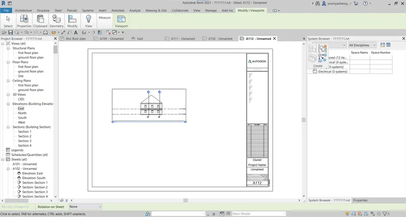
10) Create a camera specific view or a 3D view in each room ( living, dining, bed room ) . Based on the views create new shet of sheets starting A-501 (you can add as many sheets after , 502, 503.. n)to place the 3D view images.Produce the sheets as a part of project drafting.
AIM:TO CREATE CAMERA SPECIFIC VIEW IN DIFFERENT SHEETS
TOOLS AND COMMANDS USED:
- 3D VIEW
- CAMERA
- VIEW
- SHEET
PROCEDURE:
STEP-1:Open revit software and open file and open previously created file
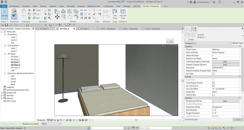
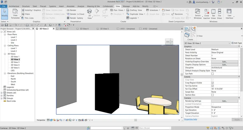
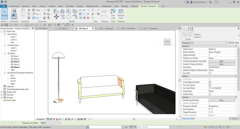
go to view tab and select 3d view and choose camera and put it at a specified place and drag the lines to show the required things

bedroom camera view:
kitchen camera view
living hall camera view:
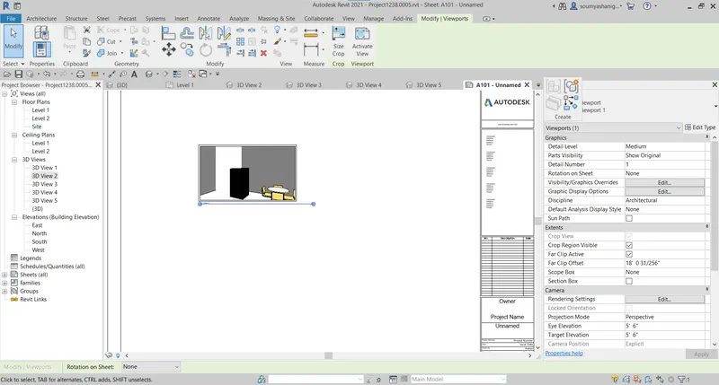
STEP-2:Go to view tab and create a sheet

STEP-3: now go to view tab and click on view then many options are available select the required view to place on sheet
STEP-4:Now add different 3 d camera view to sheet
KITCHEN
follow the same procedure to create new sheet
LIVING ROOM
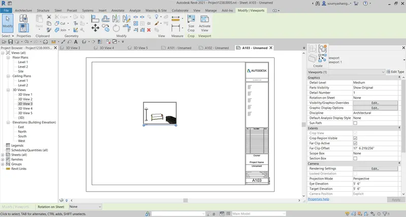
BEDROOM
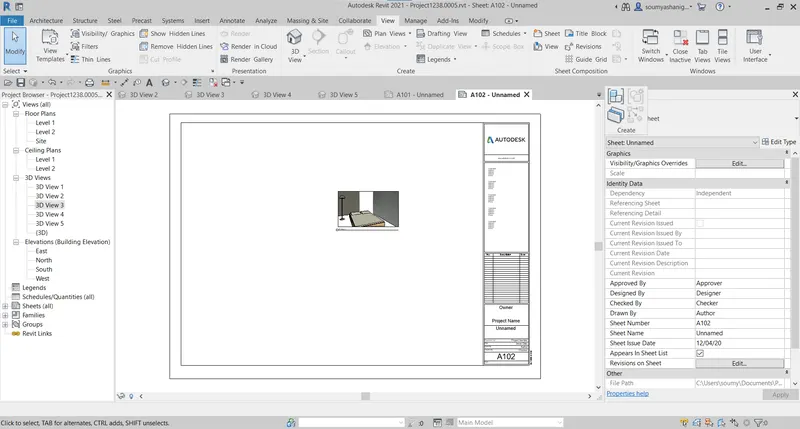
RESULT: THE DIFFERENT VIEWS WERE PLACED IN SHEET BY VIEW TAB