REVIT_Analysing the building & Report preparation_Week 8
1.Question:What are HVAC systems ? Why are they essential in modeling of buildings?
Ans) HVAC stands for heating,cooling and conditioning.HVAC systems are milestones of building mechanical systems that provide thermal comfort for occupants accompanied with indoor air quality. HVAC systems can be classifed into central and local systems according to multiple zones, location, and distribution.Primary HVAC equipment includes heating equipment, ventilation equipment, and cooling or air-conditioning equipment. Central HVAC systems locate away from building in a central equipment room and deliver the conditioned air by a delivery ductwork system. Central HVAC systems contain all-air, air-water, all-water systems. Two systems should be considered as central such as heating and cooling panels and water-source heat pumps. Local HVAC systems can be located inside a conditioned zone or adjacent to it and no requirement for ductwork. Local systems include local heating, local air-conditioning, local ventilation, and split systems.
a. Typical HVAC unit includes Distribution center
b. Collector
c. Ducts
d. Blower
- Firstly open a new file with mechanical templete and save it accordingly.
- Now click on collaborate tab and click on collaboration.
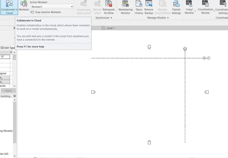
- Now draw the grids and secify the coordinate ponits as 0" 0' for both the grid lines.
- Now select the manage links option and link architectural file that we had previously worked on and reclocate the project.
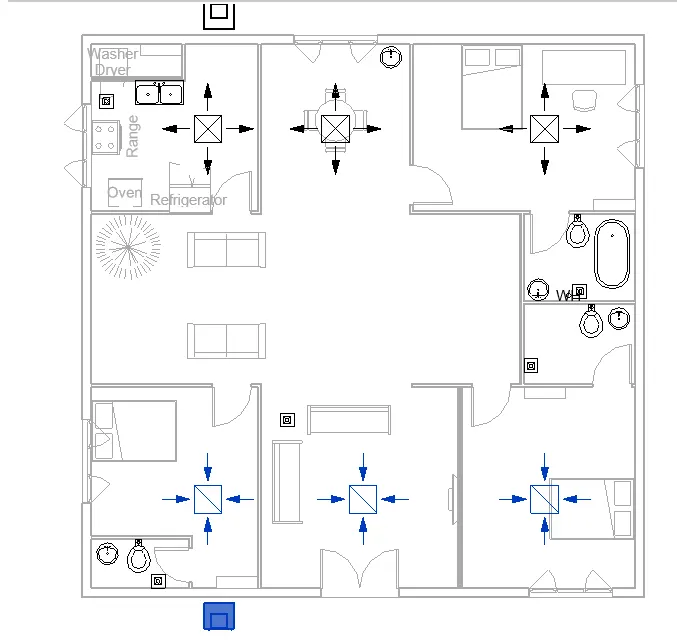
- Now select the system tab and select air terminals option and then select the type of suppliers in each room.
- Now select the mechanical unit and place the air handling unit at the appropriate place.
- Now select the elements for the room and click on the duct and select the desired layout that can be done by getting into the the top green tab and click ok.
RESULT:
Hence the HVAC coonection of a room is done.
3.Question: Use the add-ins tab to load plug-ins for robot structural analysis to your Revit software
- The primary structural elements which form the main frames and transfer both horizontal and vertical load to the foundations.
- The secondary structural elements, such as secondary beams, which transfer the loads to the primary structural elements.
- The other elements, such as partitions, which only transfer loads to the primary or secondary structural elements.
Numerical analysis of structures relies on the designer's understanding of structural behaviour, choice of appropriate software, method of analysis and above all the use of engineering judgement to know when the answers are reasonable.An intuitive approach uses broader, more dynamic reasoning skills to evaluate the behaviour of any particular structure. The key principles involved in developing this kind of understanding of structural behaviour are:
- To consider the deformed shape of a structure.
- To use statically determinate simple systems, so that good appreciation of the behaviour of the real structure with all its complexities can be gained.
- It is helpful to use the graphic options of the software to review input data, such as loads, and output data, such as deflections and bending moments.
Design effects a building in lot many ways as the texturing and modelling places a key role in that. It must be emphasised that, in most cases, there is more than one option for the form of the building frame.
5. Question: From the structural model developed in week 6 and 7, export the complete analytical model to robot structural analysis.
a. List your assumptions on what boundary conditions will be realistic for analysis approach
b. Use the design standards to decide what loads must be applied to floorings based on the type of structure decided
c. List the load combinations and include them in analysis model
d. Analyze the building and report the following results
i. Maximum Moment in each floor for all Load Combinations
ii. Maximum Displacement in each floor for all Load combinations
iii. Lateral Displacement in building for all Lateral Load combinations
e. After analysis , do you think you have a better approach or idea in modeling structural members ?
Ans) a. One of the most difficult aspects of setting up an FEA (finite element analysis) model to simulate the real world is applying realistic boundary conditions. This means understanding how the structure is loaded by external forces and how it is constrained from moving globally in space. Sometimes the distinction between whether a structure should be fixed to the ground or loaded externally can become a little blurred. It is up to the analyst to decide how to deal with this.
- Visualization of the analytical model depends on the project template, view template, view parameters, and object styles. The structural analysis project template contains two structural analytical plan views and a 3D analytical view.The known force or displacement may have some magnitude or it may be zero. For example, we may know that there are locations on our structure that have no external force. This would be a zero force boundary condition.
- A displacement boundary condition that is zero is equivalent to the structure being held in place at that location.Boundary conditions are typically expressed in terms of applicable degrees of freedom. A degree of freedom (DOF) is simply a single direction that a point on a structure can move freely. In two dimensions (2D), each free point on a structure has three different possible DOFs: one horizontal, one vertical, and one rotational.
- The most common displacement boundary conditions in structural analysis are those that restrain the movement of the structure in one or more degrees of freedom at a point. These restraints are also called supports. At these restraint locations, we know that the displacement of the structure in each restrained degree of freedom is zero; however, we don't know what force is necessary to hold the degree of freedom in that restrained position. This force is called the reaction force.
b.Loads to be applied on floorings based on the type of structure decided are:
- Since it is a residential building we need to apply the following loads:-
-> Dead load -> Live load -> Earthquake load
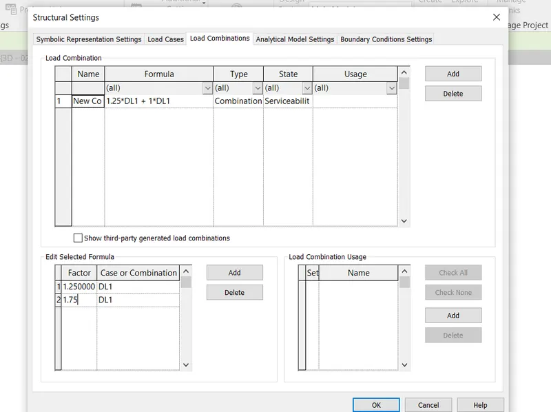
c.Load combinations that are to be applied on to our residential building are:
1.5(DL+LL) as my building is G+3 wind load is not applicable
0.9DL+-1.5EL
(+ELx+-0.25ELy)
(+-0.25ELx+-ELy)
(ELx+-0.25ELy)
(ELy+-0.25ELx)
PROCEDURE:
- Firstly open the structural file that was created last week.
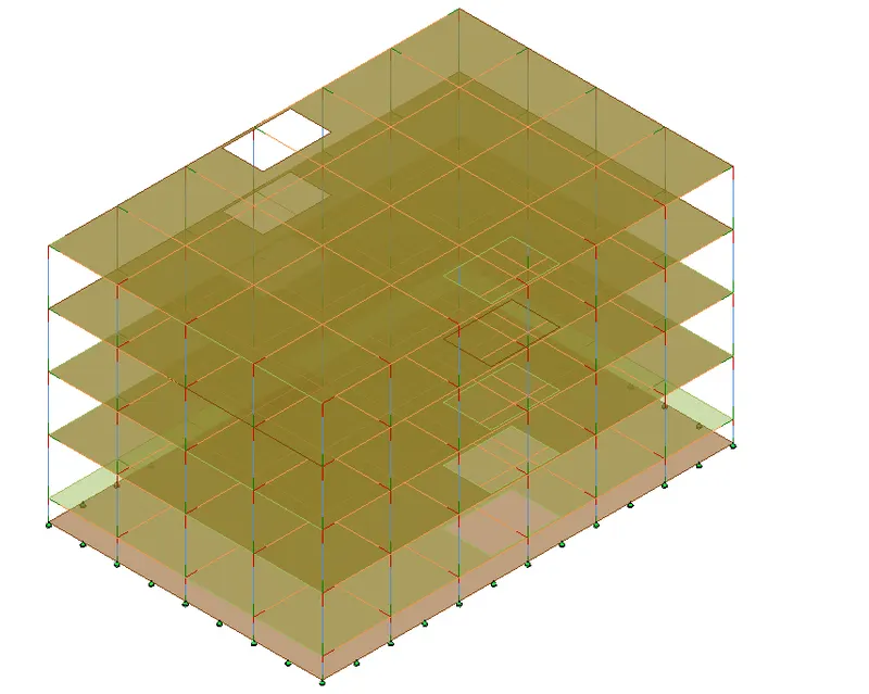
- Now open the 3D view and now select the analyze tab and click on boundary conditions,now select the type of boundary you required.
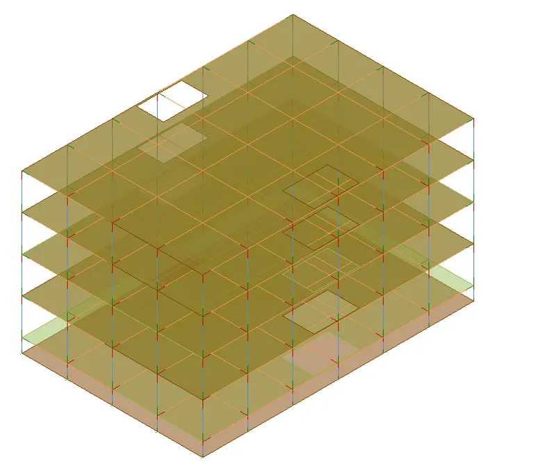
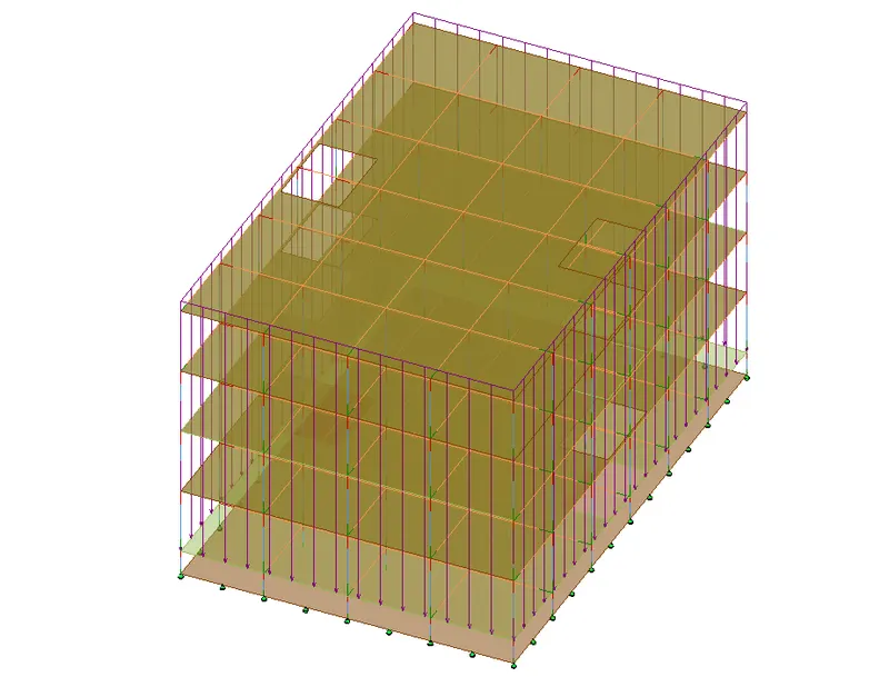
- Now again go to the analyze tab and click on loads,now select the type of loads that you wish to place.
- Now click on load combinations and enter the desired value and click value.
RESULT :
Hence the analze part of the building is done.
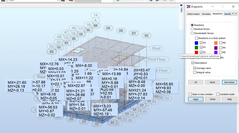
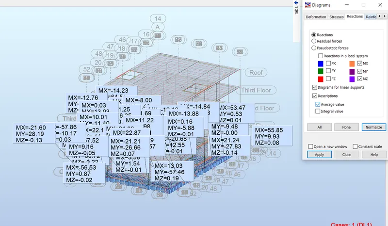
d.Analyzing the building is done and the following are the results.
PROCEDURE:
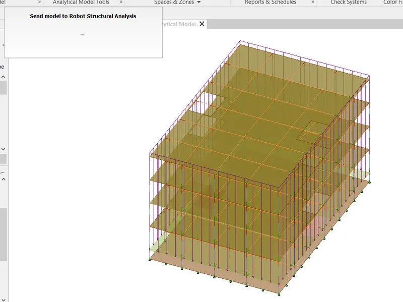
- Firstly after the analyzing part now click on the robot structural analysis and click on the send link option.
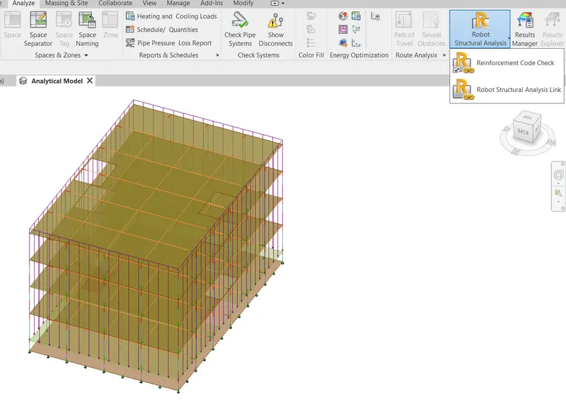
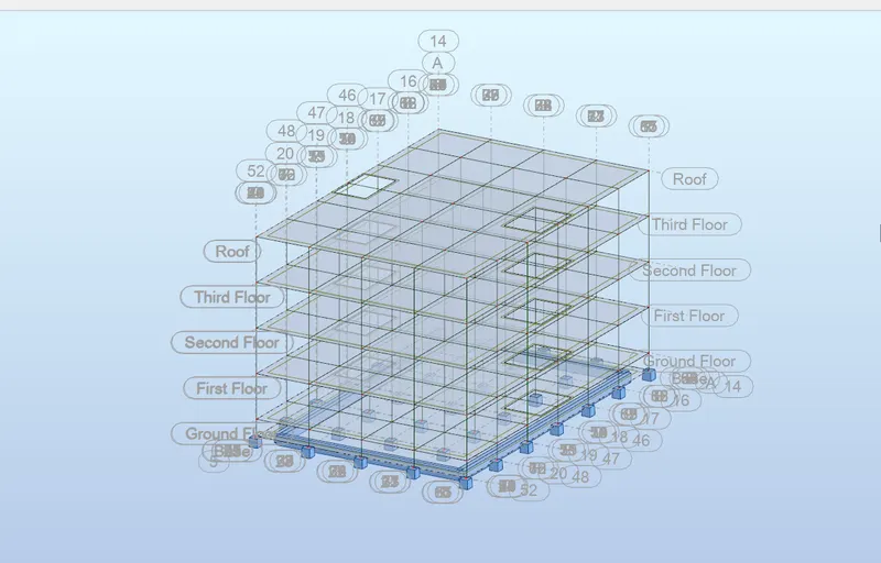
- Now open the Roboat Structural Analysis software and we can see the exported model there.
- Now click on the results tab and click on the diagrams of bars and you will be directed to a dialog box.
- Now tick on the options that you desired to see on the screen.
e.After analysis , do you think you have a better approach or idea in modeling structural members ?
I do need to think of a new idea since the values that i given are not that appropriate.
6.Question:What is energy analysis and why do we need to consider it while modeling in Revit?
Ans)Energy optimization is the automatic creation of a complete and accurate energy model directly from an architectural model.This approach means that no special model authoring is required for analysis. It works with a variety of modeling styles and levels of detail.To take advantage of this approach, you need to understand the range of modeling styles and practices supported, how architectural model elements into energy model elements, and what makes accurate and reliable energy model geometry.
Conceptual mass modeling is a useful tool for preliminary analytical energy studies which is a required component of 3D BIM modeled structures. Once the model has been completed, pertinent data such as building location, building type and zones, regional climate, and construction material is input to generate whole building heating and cooling loads and to compare the performance of alternate building design strategies. From this mass modeling analysis, changes to the structure’s orientation, building form, or envelope design can be qualified early in the design process.
Building simulation is commonly divided into two categories: Load Design, and Energy-Analysis.
Energy-Analysis or Energy-modeling is used to:
- Predict the monthly energy consumption and bills
- Predict the annual energy cost
- Annual CO2 emmissions
- Compare and contrast different efficiency options
- Determine life cycle payback on various options
The ultimate goal is to reduce consuption of non-renewable resources,minimize waste and create healthy and productive environment.