REVIT_Analysing the building & Report preparation_Week 8
1) What are HVAC systems ? Why are they essential in modeling of buildings
Answer:
The initials HVAC stand for Heating, Ventilation and Air Conditioning. They describe the functions of an HVAC system. This mechanical system’s design is primarily an attempt to take control of the environmental conditions inside the space you work.
A good HVAC system aims to provide thermal control and indoor comfort, and one that is designed using the principles of thermodynamics, fluid mechanics, and heat transfer.
The big air conditioner boxes that you might see on top of apartment blocks or offices are examples of (the visible part of HVAC systems. They’re typically deployed in large industrial buildings, skyscrapers, apartment blocks, and large interior environments. They’re also an essential component of environments where there are health regulations requiring that temperature and humidity be kept at certain levels, using air taken from outside.
But heating and cooling systems you use in your home are also HVAC systems. They may take a different form, but many of the fundamental principles determining how they operate, as well as their efficiency, crosses over from the smallest of personal devices right through to the biggest commercial installations.
Why are they essential in modeling of buildings:
Why HVAC is important will differ in each of its applications, but the goal for most residential and commercial HVAC customers is comfort, especially in parts of the country with extreme weather. Luckily, San Diego offers near-perfect weather year-round with only a few months out of the year seeing extreme heat and cold. Because the seasons offer mostly bearable, if not great, weather, heating, and cooling are not always a necessity, but are always welcome respite during the hot summer days and cool winter nights, especially in the inland areas.
There are many great options for homeowners when choosing a new heating and cooling system. Whether you’re investing in an HVAC solution for a larger home, commercial building, small condo unit, craftsman style home without ducting solutions, or any other manner of residential and commercial space, an HVAC installation can produce massive benefits when it comes to temperature control and energy efficiency.
2) From week 7 assignment, based on the building designed use the same revit file to design a HVAC system for each floor to cover the topics included in class.
a. Typical HVAC unit includes Distribution center
b. Collector
c. Ducts
d. Blower
Aim:
To Creating the HVAC system in week 7 assignment using Revit application.
Tools Used:
* System
* Duct
* Air terminals
* Mechanical Equipments
Procedure :
Step 1:
1) Open Revit application
2) Choose either Mechanical/System template from home screen
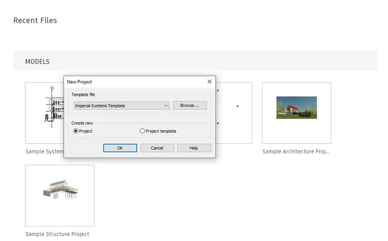
Step 2:
1) Click System tab and choose air terminal tool
2) Click Load family
3) Go to library and choose optimal air handlin units
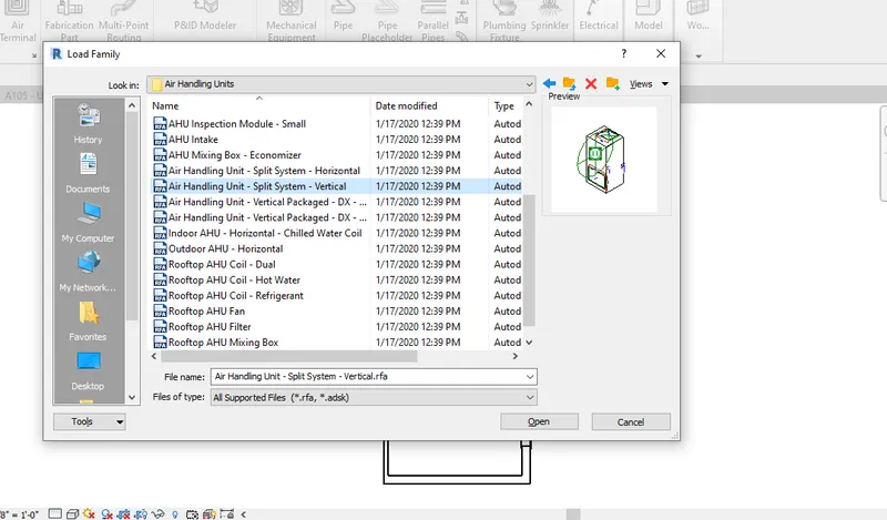
Step 3:
1) After placing all the diffuser and air terminals in floor area, click all the objects at once.
2) Select Duct option from modify tab
3) Naming the suitable name of our created duct system
4) Then click ok
5) Select Generate layout option and choose optimum layout for the duct
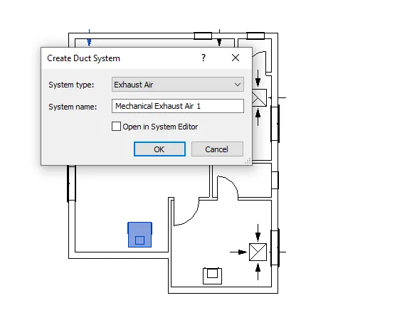
Step 4:
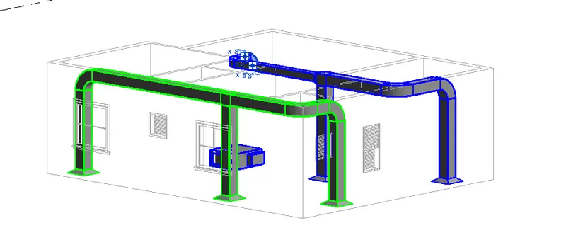
1) After creating a layout for the duct it shows 2 different colour duct layout
2) Blue colour duct indicates discharge of air from the terminals whereas green colour indicates the inhale of air from the terminals to the room area.
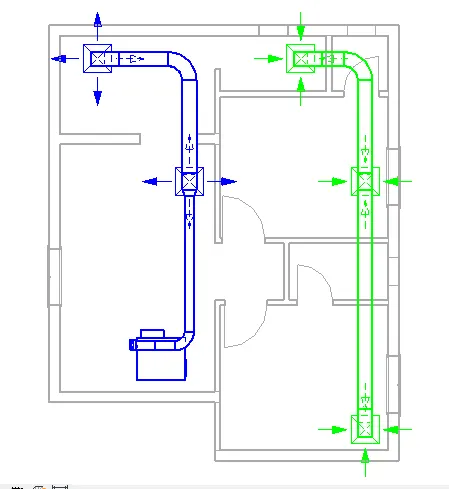
Step 5:
1) Click the 3d view of the system layout from view tab
2) Thus the layout of ducts is to be on created successfully.
3) Use the add-ins tab to load plug-ins for robot structural analysis to your Revit software
Answer:
Aim:
To plug in the Robot structural analysis toolkit using add-ins tab in Revit application.
Tools Used:
* Add-ins
Procedure:
Step 1:
1) Open Revit application
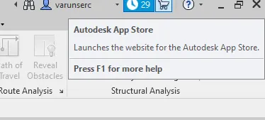
2) Click purchase option from the top of the application
Step 2:
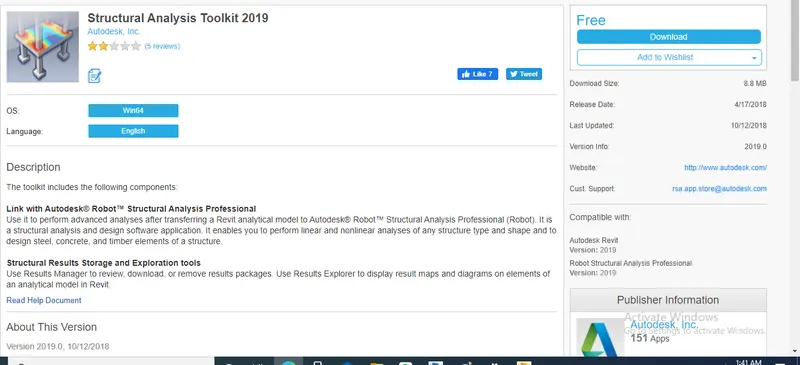
1) Search Robot Structural analysis Professional
2) Click download and extract it into your computer
3) Once the installation is finished Robot structural analysis is ready to use.
4) Why do we need to assess buildings /analyze while modeling elements ? Does design affect modeling in anyways ?
Answer:
A building condition assessment can also be useful if you are planning to renovate the building, because your contractor will review the building condition assessment to help determine total renovation costs.
Not only can defects revealed in a building inspection be points for negotiation with the seller, but knowledge of required upgrades can also help you plan for adequate financing. A building condition assessment helps shed light on what costs to expect immediately and in the next few years.
5) From the structural model developed in week 6 and 7, export the complete analytical model to robot structural analysis.
a. List your assumptions on what boundary conditions will be realistic for analysis approach
b. Use the design standards to decide what loads must be applied to floorings based on the type of structure decided
c. List the load combinations and include them in analysis model
d. Analyze the building and report the following results
i. Maximum Moment in each floor for all Load Combinations
ii. Maximum Displacement in each floor for all Load combinations
iii. Lateral Displacement in building for all Lateral Load combinations
e. After analysis , do you think you have a better approach or idea in modeling structural members ?
Aim:
To analyze the building and reporting the
i. Maximum Moment in each floor for all Load Combinations
ii. Maximum Displacement in each floor for all Load combinations
iii. Lateral Displacement in building for all Lateral Load combinations
Tools Used:
* Beam
* Coloumn
* Robot Structural analysis toolkit
* Loads
Procedure:
a. List your assumptions on what boundary conditions will be realistic for analysis approach
Firstly i assume that the load area is entire floor area of ground floor of the building.
b. Use the design standards to decide what loads must be applied to floorings based on the type of structure decided
Since my structure is residential unit the possible loads of mine is Dead load, Live load and wind load
c. List the load combinations and include them in analysis model
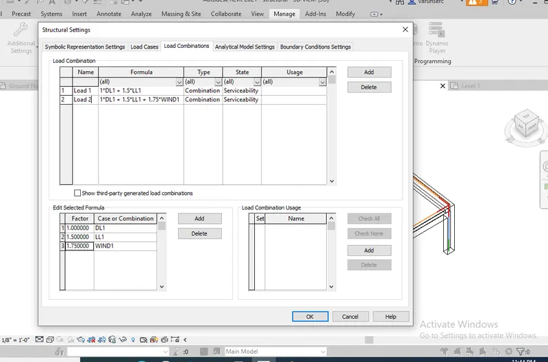
There is 2 load combination:
1) Load combination 1 = 1*Dead Load + 1.5* Live load
2) Load Combination 2 = 1*Dead Load + 1.5* Live load + 1.75 * Wind load
Step 1:
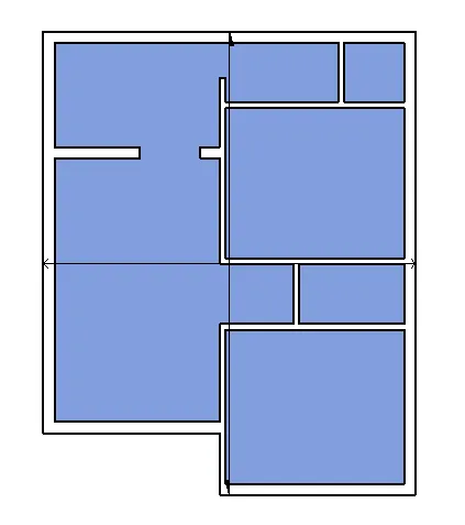
1) Open a floor plan which already created in previous week
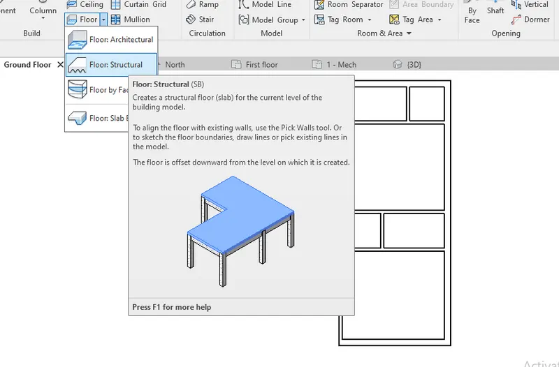
2) Create floor using floor tool in Architectural tab
3) Place the floor in the boundary area of the plan
Step 2:
1) After creating the floor create a span direction
2) Click Span direction in modify tab
3) Choose draw tool option and create a span line
4) Click tick mark and finish creating the span direction
5) Now the Span direction is created vertically on middle of the floor plan
Step 3:
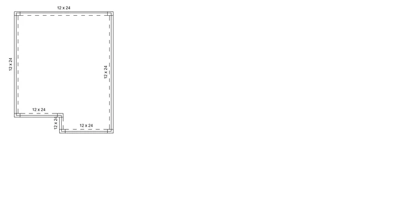
1) Place a beam and clolumn on the floor by clicking beam in Structural tab
2) Choose 12x24 Rectangular concrete beam
3) Similarly choose 12x18 rectangular coloumn
3) Place it both on the floor
Step 4:
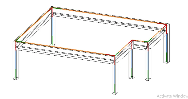
1) After creating the beam and column switch your model into 3d view
2) Orelse switch it into analyze 3d model
Step 5:
1) Click Loads in Manage tab
2) Add the new load combination
3) Create a applied loads on the floor
4) Naming the appropriate name for the load combinations
5) Then click Ok
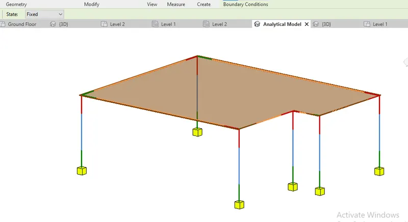
Step 6:
1) After applying the load condition create a boundary condition for the floor
2) Go to modify tab click boundary condition
3) Choose type as fixed
4) Click the place you want to create a boundary.
5) Click tick mark and finish
Step 7:
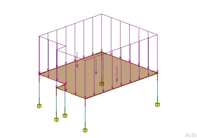
1) Click load in manage tab
2) Select the type of load and choose the load area
3) Place the point load and draw the load area by clicking the draw tool
4) Click tick mark and finish
Step 8:
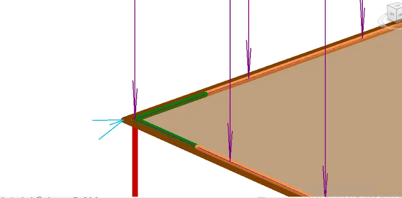
1) Create a wind load by clicking the point load and edit the fz value
2) Fx value =0.1 and fz value =0
3) Click apply
Step 9:
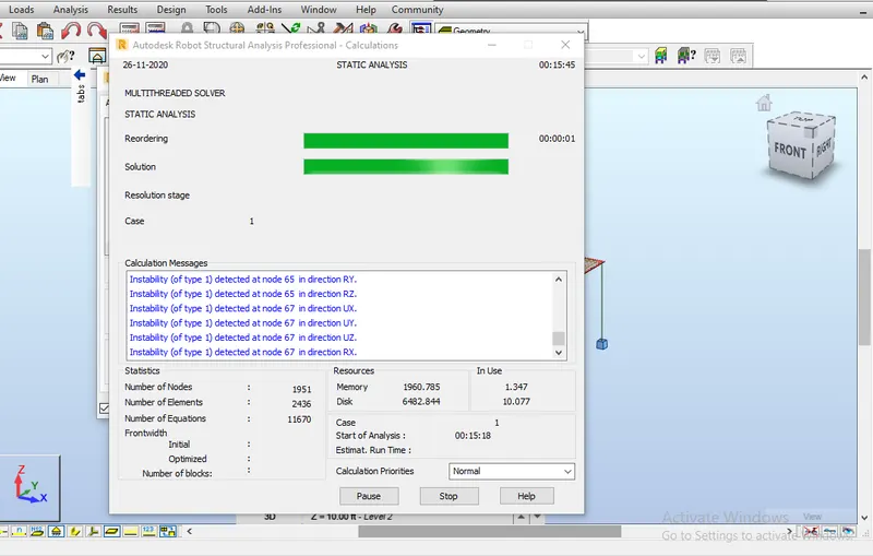
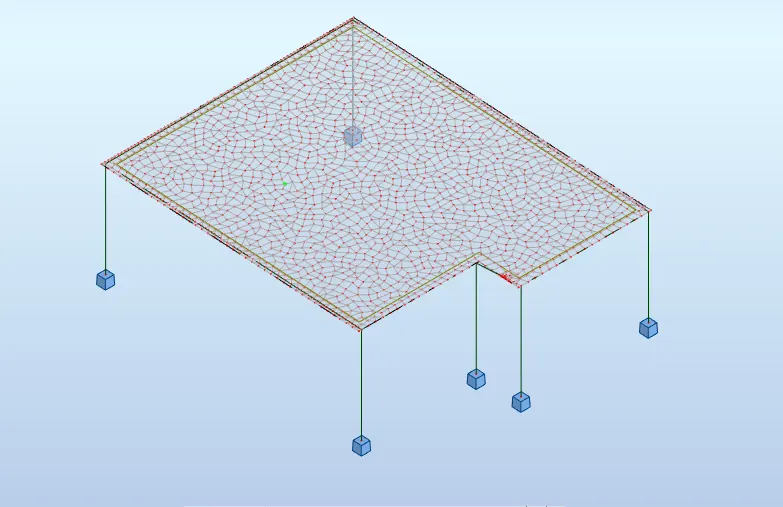
1) After applying the necessary loads go to analyze tab
2) Click Robot structural analysis and choose robot structural link
3) Then the file will open on Robot structural tool
4) Click analyse and choose calculation
5) Now the file will start analysing
Step 10:
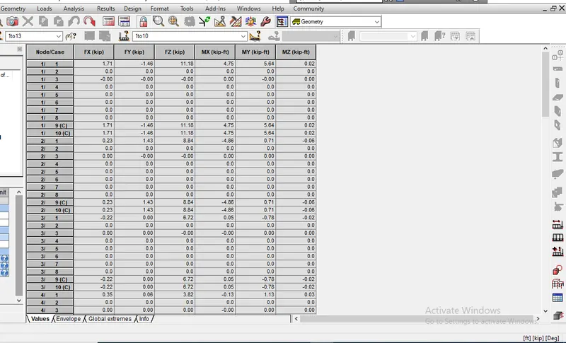
1) Click result tab
2) Select Reaction option
3) Reaction values will appears on the screen
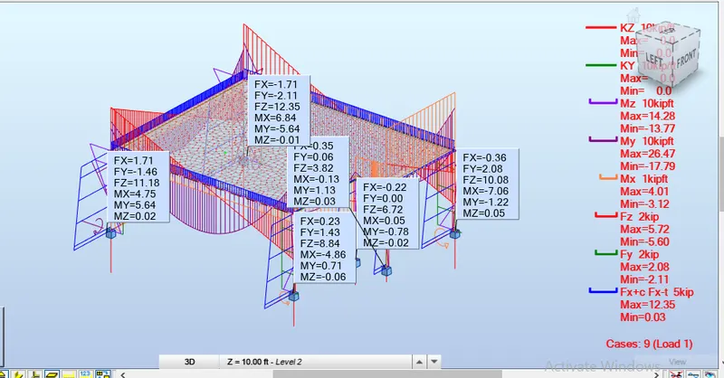
Step 11:
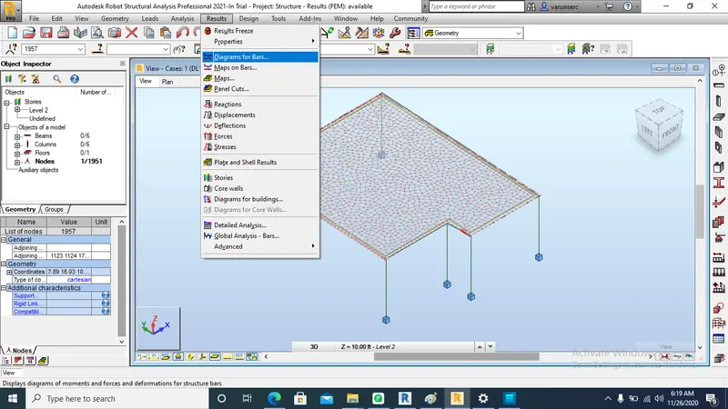
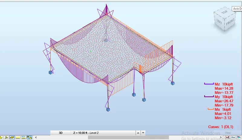
1) Click result and choose Diagram
2) Tick mark the mx my mz for moment
3) After clicking the moments the moment diagram will appear
4) It shows each load combination which we assign earlier
Step 12:
1) For displacements, click result
2) Choose Displacement option
3) Then the screen will shows the displacement values of each load combinations
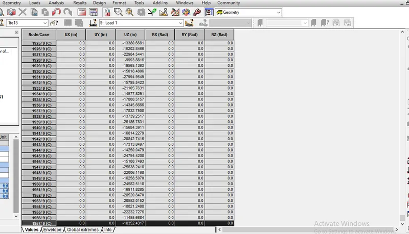
Step 13:
1) In the diagram option check all the boxes
2) The screen will shows momentum, diplacement and lateral load for each load combination.
6) What is energy analysis and why do we need to consider it while modeling in Revit ?
Answer:
A process in the design phase which one or more building energy simulation programs use a properly adjusted BIM model to conduct energy assessments for the current building design. The core goal of this BIM use is to inspect building energy standard compatibility and seek opportunities to optimize proposed design to reduce structure's life-cycle costs.
• Save time and costs by obtaining building and system information automatically from BIM model instead of inputting data manually
- • Improve building energy prediction accuracy by auto-determining building information such as geometries, volumes precisely from BIM model
- • Help with building energy code verification
- • Optimize building design for better building performance efficiency and reduce building life-cycle cost.