Reinforcement Detailing of Beams from ETABS output
AIM:
- To carry out the analysis and design for RCC moment resisting frame of the given ETABS file for G+4 building.
- To provide the detailing of longitudinal and shear reinforcement for two continuous beams along grid A and grid 3.
- To sketch the beam elevation details using AutoCAD.
- To provide the reasons of failure of middle span along grid A.
INTRODUCTION:
- Beams are horizontal structural elements that support lateral loads.
- Reinforced concrete beams receive load from the floor slab, in addition to that loads such as wall loads, service installation, etc., will be transferred from beam to column.
- The design and detailing of RC beams involve the selection of the proper beam size and the quality of longitudinal and shear reinforcement that will satisfy ultimate and serviceability limit state requirements.
- After that, it's critical that the beam reinforcements are appropriately positioned and arranged on site to avoid building mistakes.
PROCEDURE:
- Open the ETABS software.
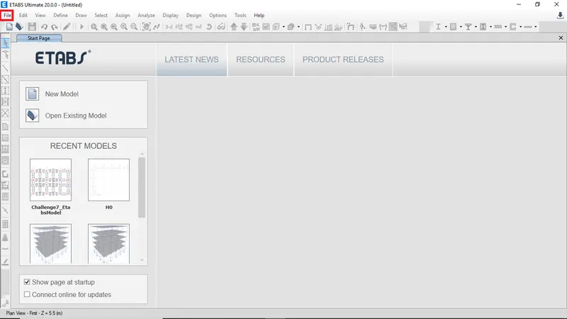
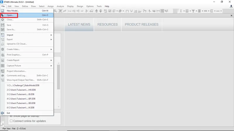
- Then goto File menu then click on open to open the provided ETABS file.
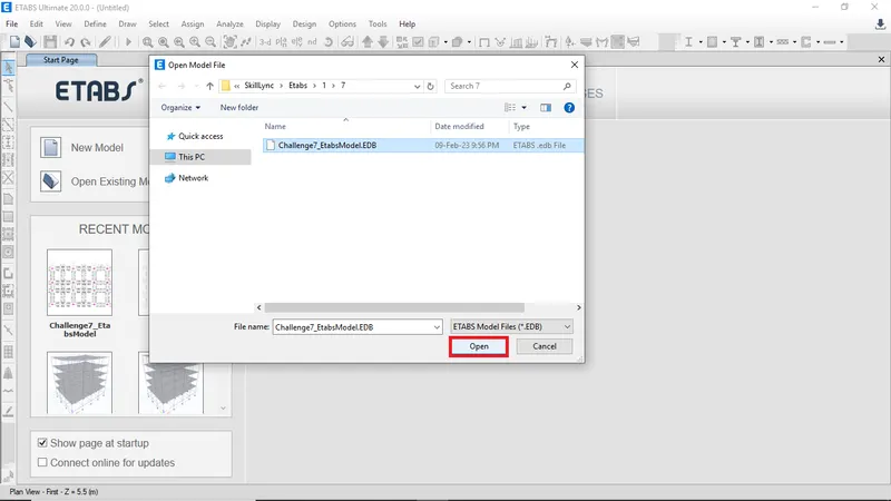
- Browse the ETABS file then click open
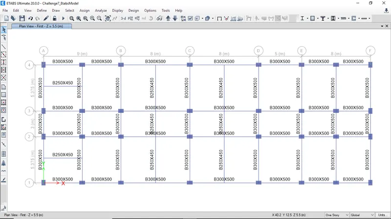
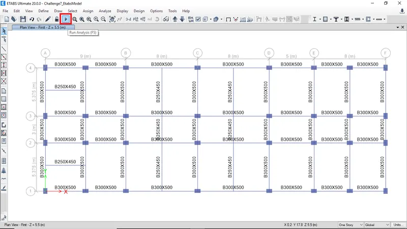
- Check the load combination then click Run to run analysis
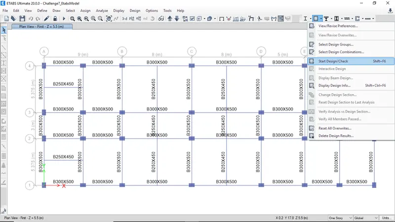
- After successful completion of analysis then click on concrete frame design.
- In the concrete frame design click on start design/check.
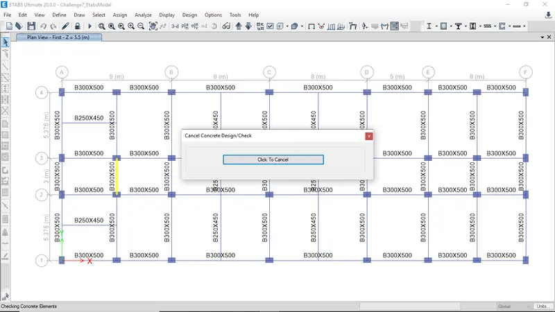
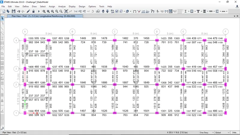
- After completion of design check it will display the longitudinal reinforcement details.
- Then Switch to First floor plan view to view the longitudinal reinforcement results.
- To view shear reinforcement details click in concrete frame design then select display design info
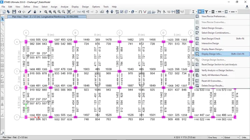
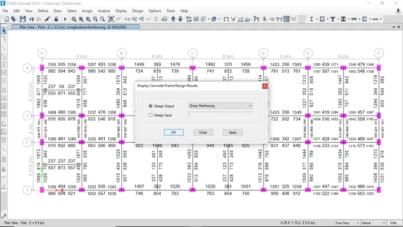
- Select shear reinforcing from thedropdown and click ok
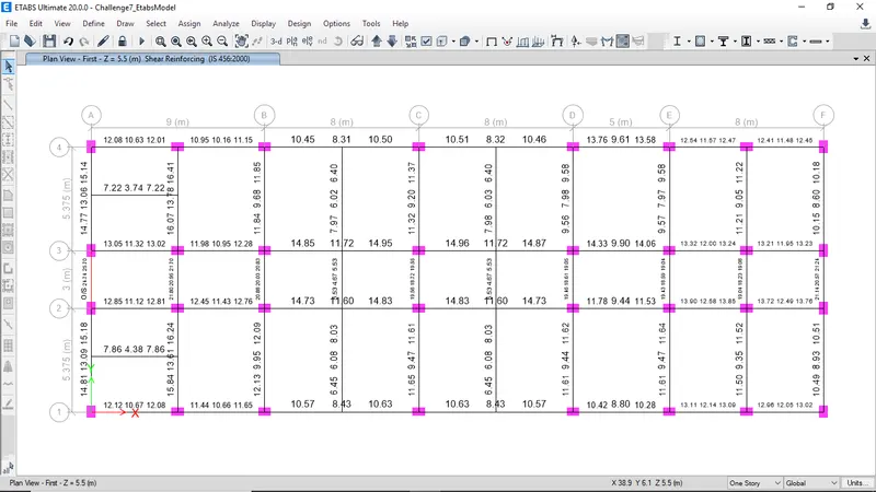
- The shear reinforcement results will be displayed
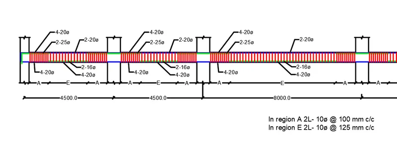
- Design of 3 span continuous beam along grid A
Longitudinal reinforcement of beam along grid A (mm2)
Top reinforcement
Maximum top reinforcement Ast at support = 2045 mm2
Provide 4-20 mm dia bars in first layer and 2-25 mm dia bars in second layer at support top.
Top midspan reinforcement
Maximum top reinforcement Ast at mid span = 511 mm2
Provide 2-20 mm dia bars at midspan top.
Bottom reinforcement
Maximum bottom reinforcement Ast at support = 1945 mm2
Provide 4-25 mm dia bars at support bottom.
Bottom midspan reinforcement
Maximum bottom reinforcement Ast at mid span= 789 mm2
Provide 2-25 mm dia bars at midspan top.
Shear reinforcement of beam along grid A (cm2)
Maximum shear reinforcement Ast at support = 1518 mm2
Provide 2L stirrups of 10 mm dia at a spacing of 100 mm
Maximum shear reinforcement Ast at mid span = 1309 mm
Provide 2L stirrups of 10 mm dia at a spacing of 120 mm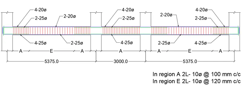
- Design of 7 span continuous beam along grid 3
Longitudinal reinforcement of beam along grid A (mm2)
Top reinforcement
Maximum top reinforcement Ast at support = 1940 mm2
Provide 4-20 mm dia bars in first layer and 2-25 mm dia bars in second layer at support top.
Top midspan reinforcement
Maximum top reinforcement Ast at mid span = 485 mm2
Provide 2-20 mm dia bars at midspan top.
Bottom reinforcement
Maximum bottom reinforcement Ast at support = 1105 mm2
Provide 4-20 mm dia bars at support bottom.
Bottom midspan reinforcement
Maximum bottom reinforcement Ast at mid span= 1501 mm2
Provide 4-20 mm dia bars in first layer and 2-16 mm dia bars in second layer at midspan.
Shear reinforcement of beam along grid A (cm2)
Maximum shear reinforcement Ast at support = 1496 mm2
Provide 2L stirrups of 10 mm dia at a spacing of 100 mm
Maximum shear reinforcement Ast at mid span = 1200 mm2
Provide 2L stirrups of 10 mm dia at a spacing of 125 mm
In the provided ETABS G+4 building model, the marked member in the below image is failed due to higher value of shear force.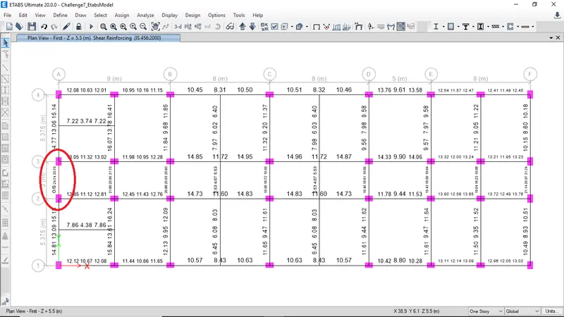
The shear capacity of the beam has been exceeded. The beam has been failed due to shear force and torsion together.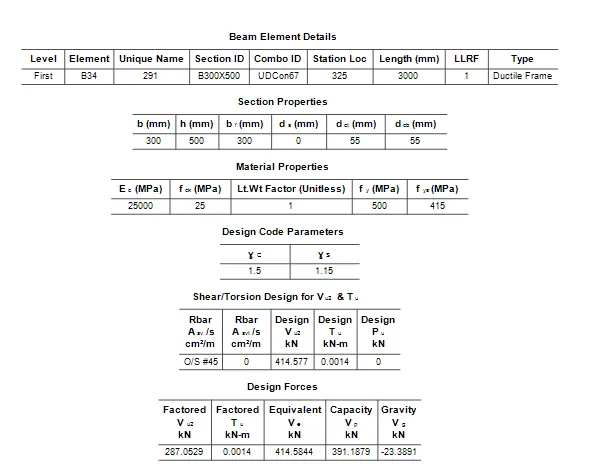
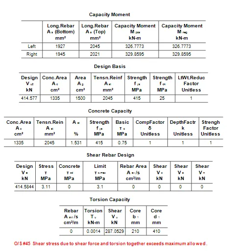
The possible way to fix this issue is by - By decreasing the applied load on beam
- Increasing the depth of the beam
- By increasing the grade of concrete so we increase the shear capacity to avoid the failure of the beam.
To calculate the value of the maximum shear force in any one of the spans in both the continuous beams, as per clause 6.3.3 (b) in IS 13920 – 2016. Also, confirm these values from the shear force demand calculated by ETABS. Please note that if longitudinal reinforcement provided is more than required (as per ETABS results), the shear force demand will vary from what is provided by ETABS.
PROCEDURE:
-
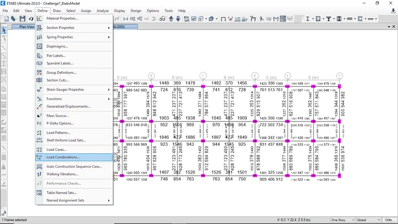
To define load combination goto define then click load combinations
-
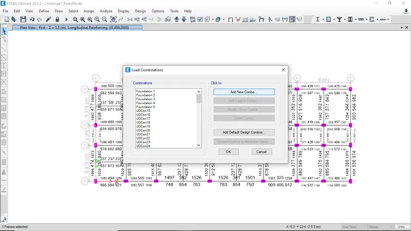
Click on Add new combination
-
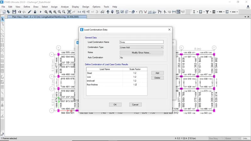
Define sway force combination as shown below
-
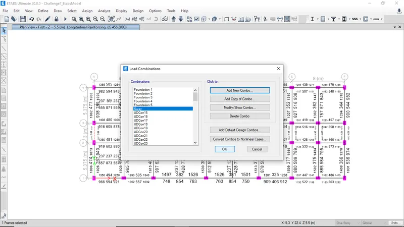
Then click ok to finish
-
Now run analysis then click on start design check in concrete frame design
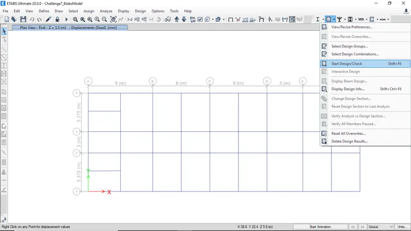
-
Then to view the shear force click on Display forces
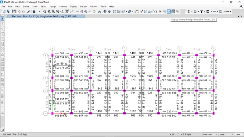
-
In that select shear 2-2 to view shear force values
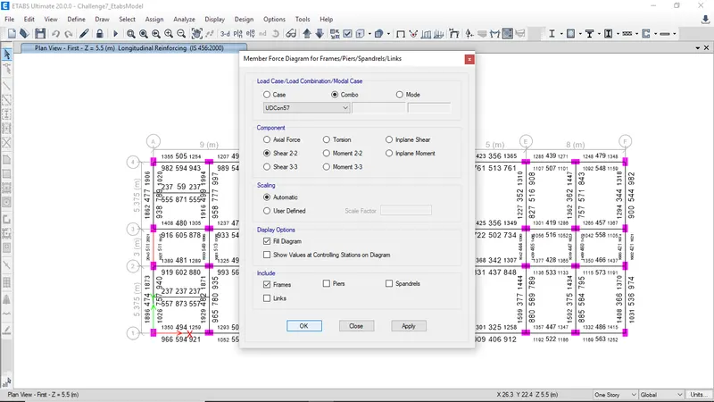
-
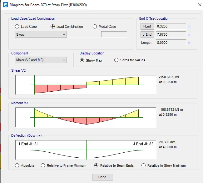
The below image show the shear force diagram
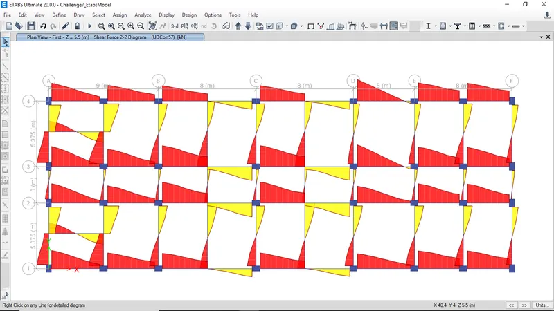
- Shear force diagram for B70 beam
Calculation of shear force - Right sway shear force
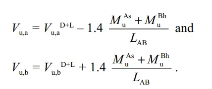
Vu,a D+L = 150.61 kN
Vu,b D+L = 149.18 kN
VAB = 8 m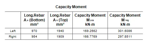
MuAs = 166.78 kN-m
MuBh = 297.85 kN-m
Substituting values in the above formula we get
Vu,a = 69.51 kN
Vu,b = 230.49 kN
Left sway shear force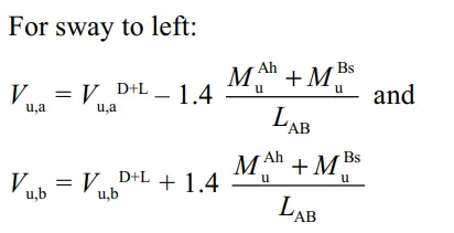
Vu,a D+L = 150.61 kN
Vu,b D+L = 149.18 kN
VAB = 8 m
MuAh = 301.61 kN-m
MuBs = 169.26 kN-m
Substituting values in the above formula we get
Vu,a = 68.21 kN
Vu,b = 231.58 kN
Existing Shear capacity of beam as per Is 456-2000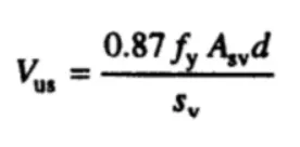
fy = 415 N/mm2
Asv = 157.08 mm2
d = 450 mm
Sv = 100 mm
Vus = 255.2 mm
The values are with in the limit. Hence it is safe.