Reinforcement Detailing of Beams from ETABS output
Detailed design of concrete buildings
1.) Detail design of beams in Etabs 2018.
The ETABS file for a G+4 building is provided. Run the analysis and design the RCC Moment ResistingFrame. The following challenge deals specifically with two continuous beams in the 1st floor.
1) 3-span continuous beam along grid A
2) 7-span continuous beam along grid 3
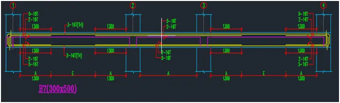
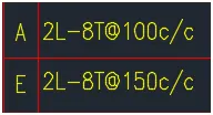
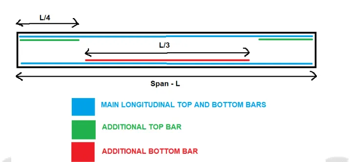
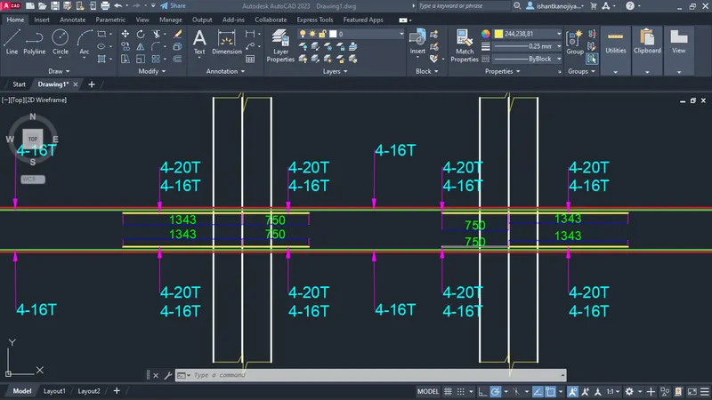
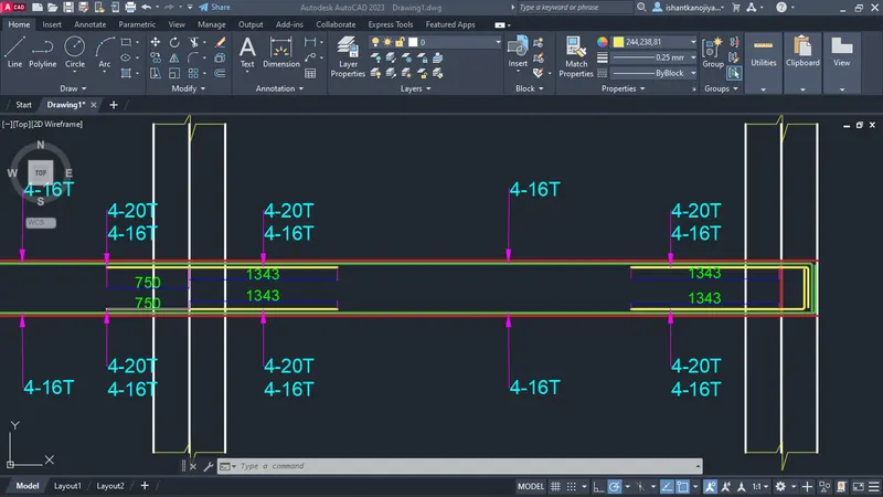
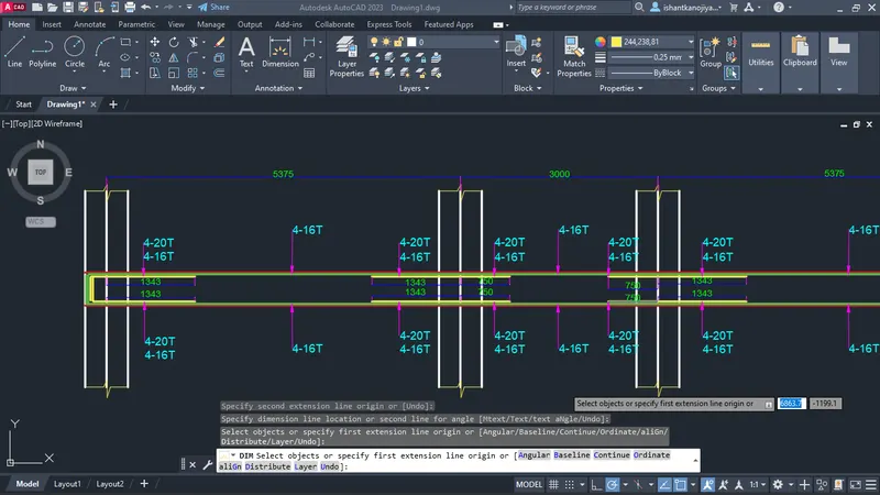
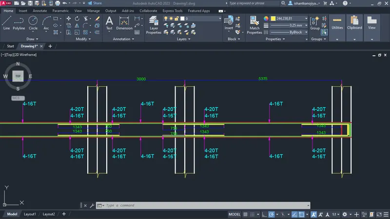
Provide details of longitudinal and shear reinforcement for the two continuous beams. Sketch the beam elevation details or draft it using AutoCAD software. A sample of how beam elevation details are prepared in consultancy firms is provided below. Participants can prepare it as per their preference:
AIM:- To Design the RCC Moment Resisting Frame of the G+4 building using Etabs.
Introduction:- In this Question, we are Designing the RCC Moment Resisting Frame of the G+4 building using Etabs and Analysis of the Continuous 3-span along grid A and continuous 7-span along grid 3.
Address the following issues thereafter.
• Provide details of longitudinal and shear reinforcement for the two continuous beams. Sketch the beam elevation details or draft it using AutoCAD software. A sample of how beam elevation details are prepared in consultancy firms is provided below. Participants can prepare it as per their preference:
Procedure:-
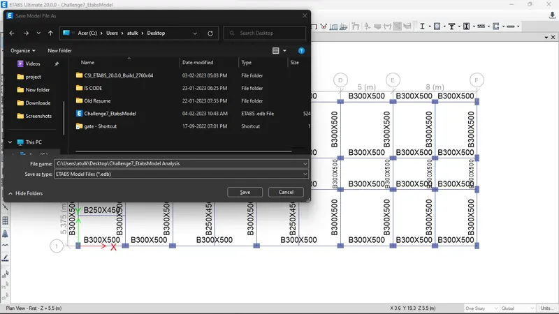
- First Open the Etabs File And Run the Analysis
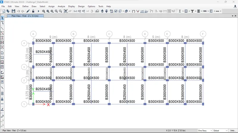
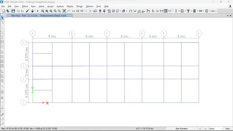
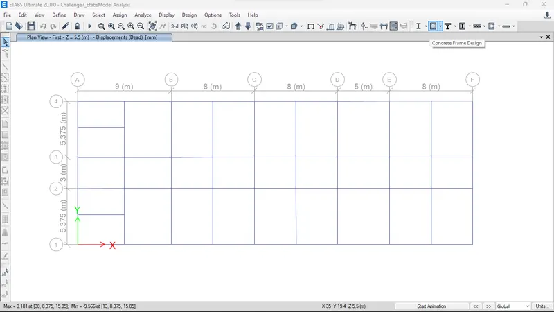
- Then Goto Concrete Frame Design
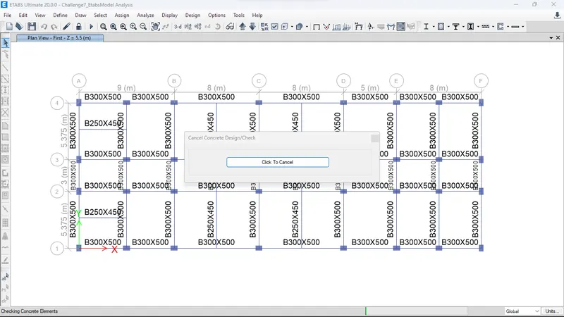
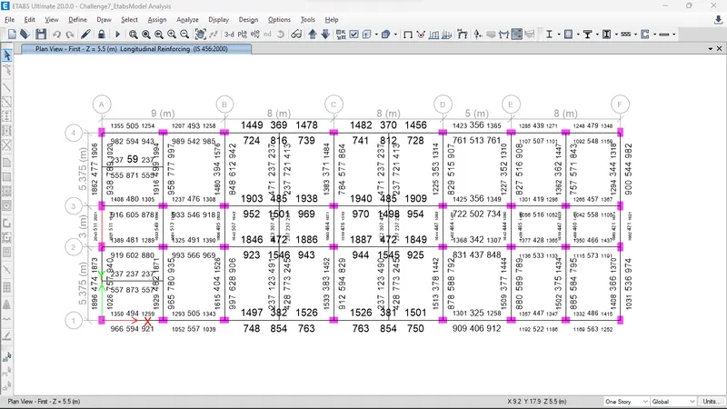
- At that point Our First Question Run And Design the Moment the Resisting Frame is Done
Now Get's Goto Next Question
Longitudinal Reinforcement of Beam(mm^2)
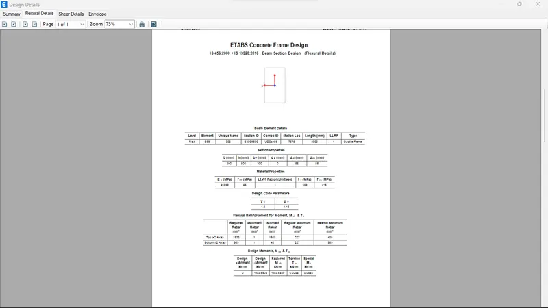
- Goto Longitudinal Reinforcement of Beam at Grid-3 from the ETABS (mm^2)
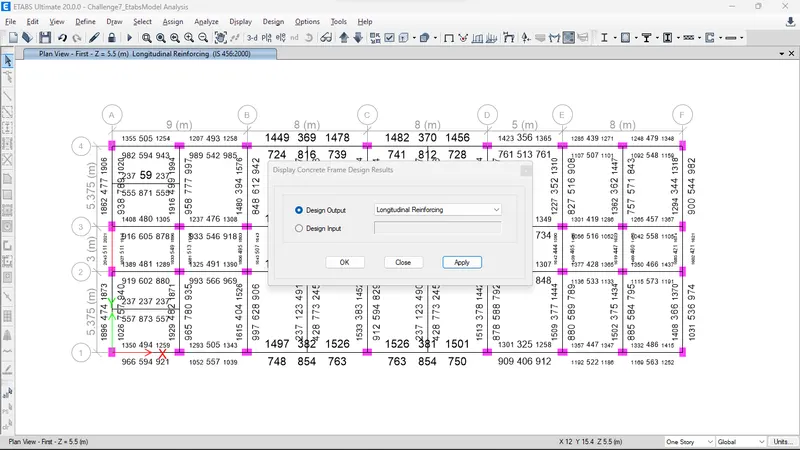

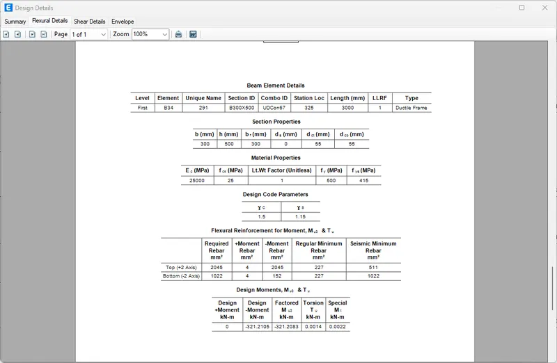
- Next Goto Longitudinal Reinforcement of Beam at Grid-A from the ETABS (mm^2)

B69 /UDCon-56along Gride-3
B34/UDcon-67along Gride-A
Shear Reinforcement of Beam(cm^2/1000mm)
- First goto Concrete frame design > then goto option >goto Display design info
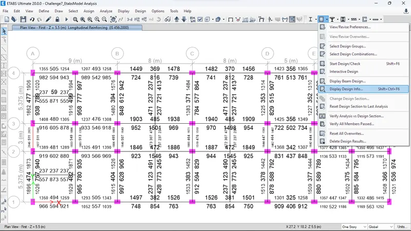
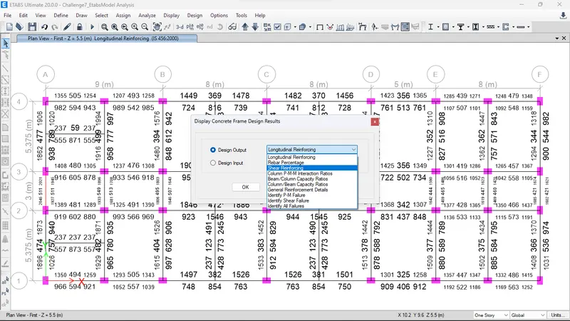
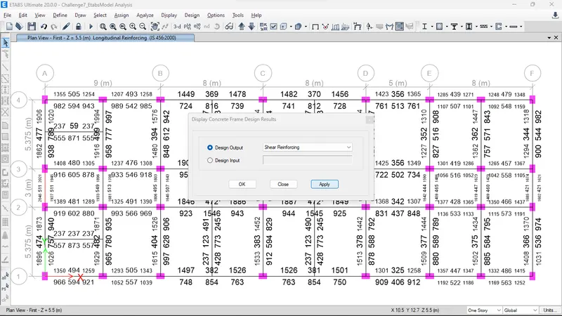
- Select Design output> Shear Reinforcement > press Apply > then Close
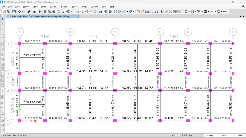
Share Reinforcement of Beam at Grid-3 from the ETABS (cm^2/1000mm)

Shear Reinforcement of Beam at Grid-3 from the ETABS (cm^2/1000mm)
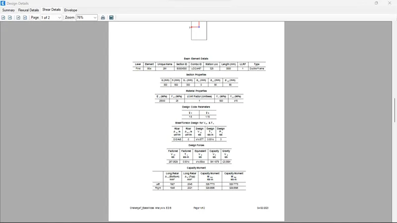
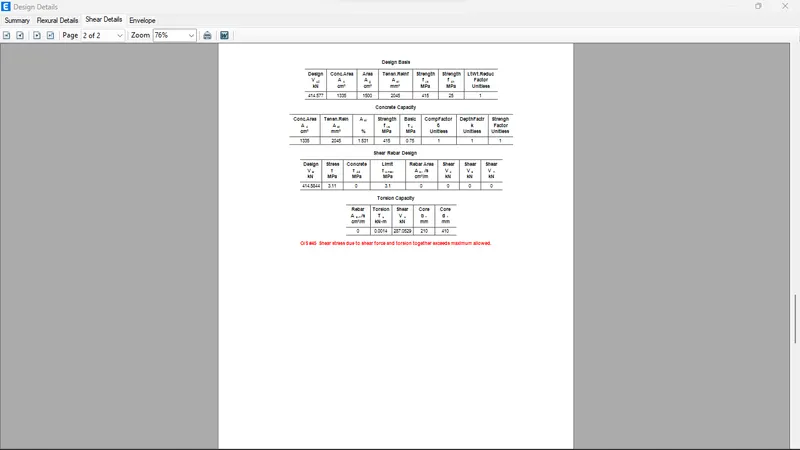
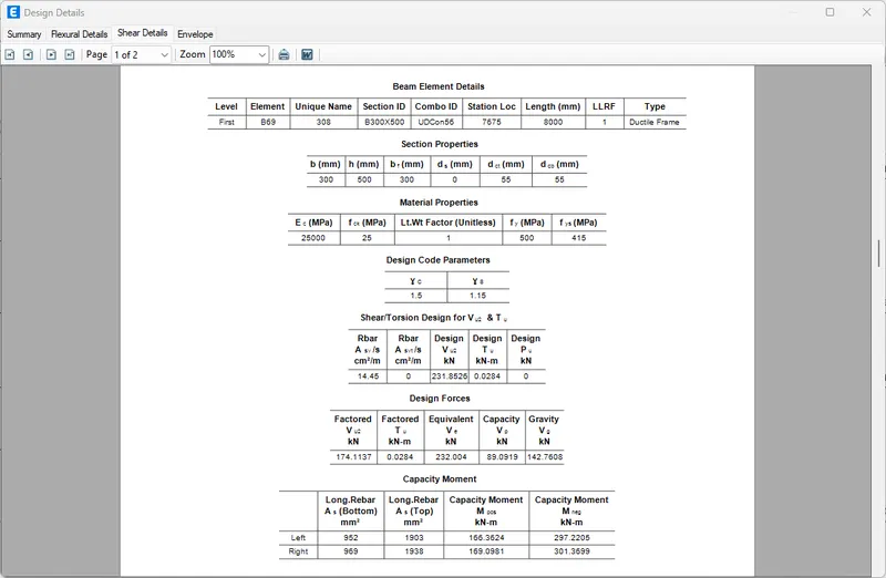
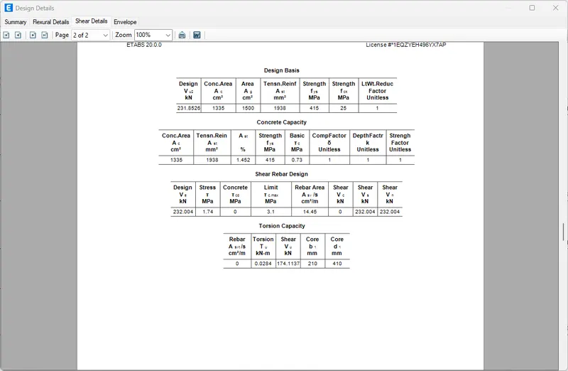
 As we see mid span is indicate bema O/S -Overstressed
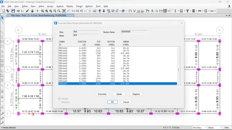
B69/UNcon-56
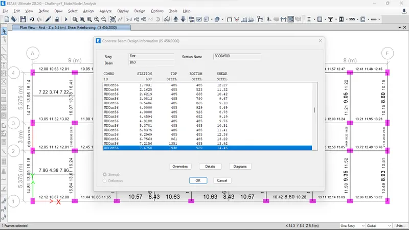
 .
.
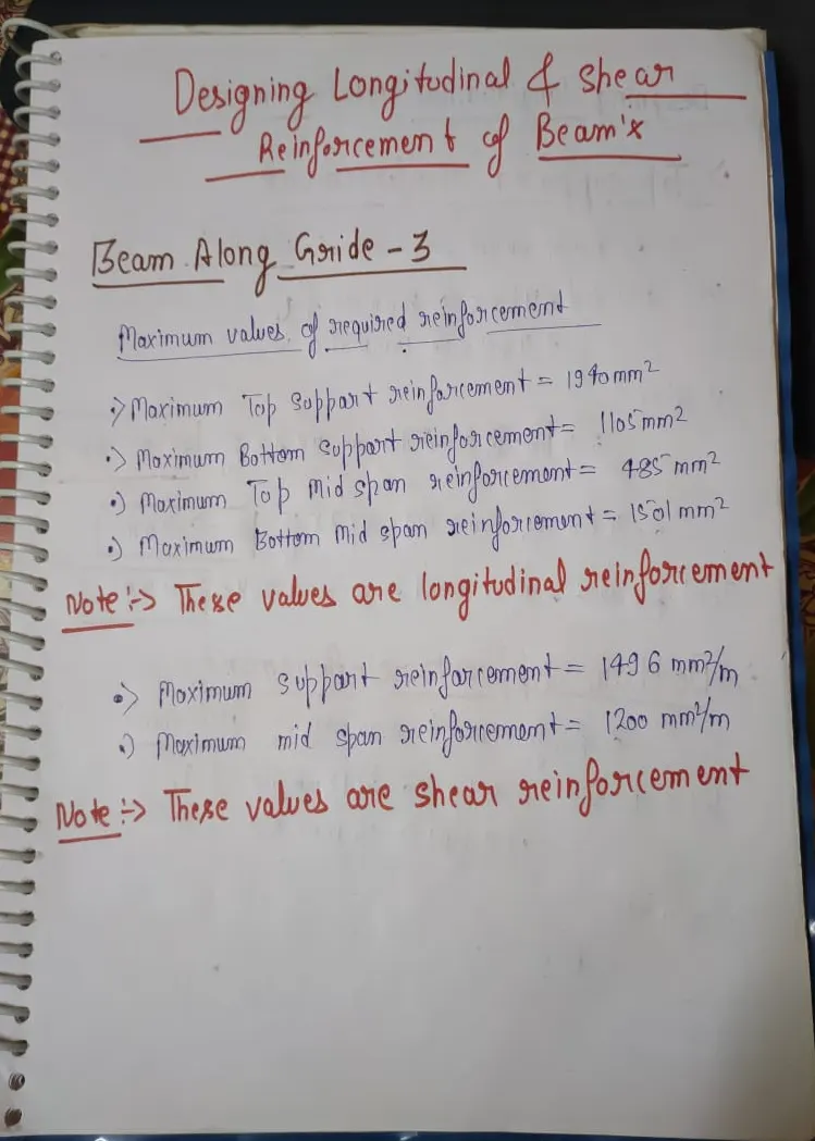
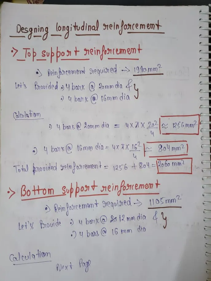
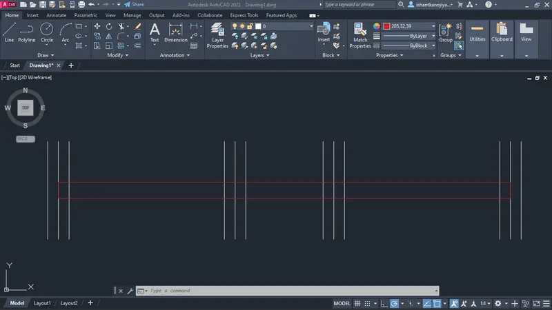
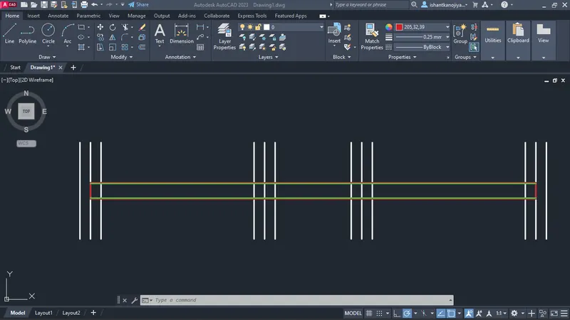
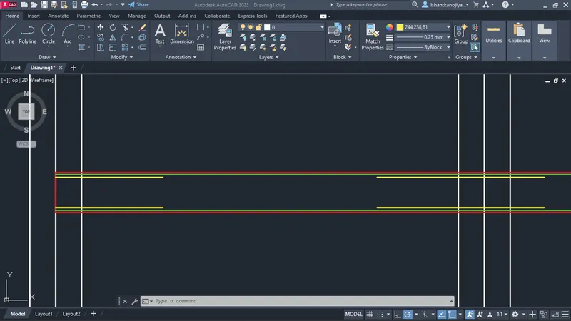
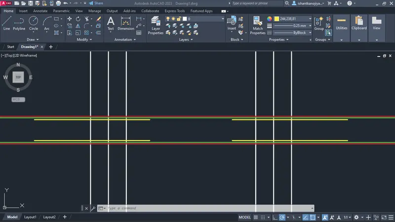
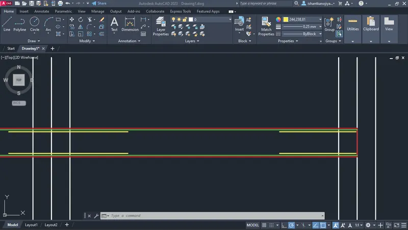
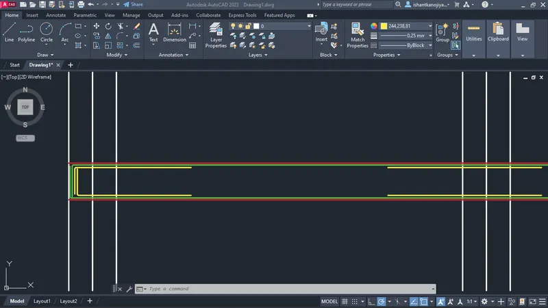
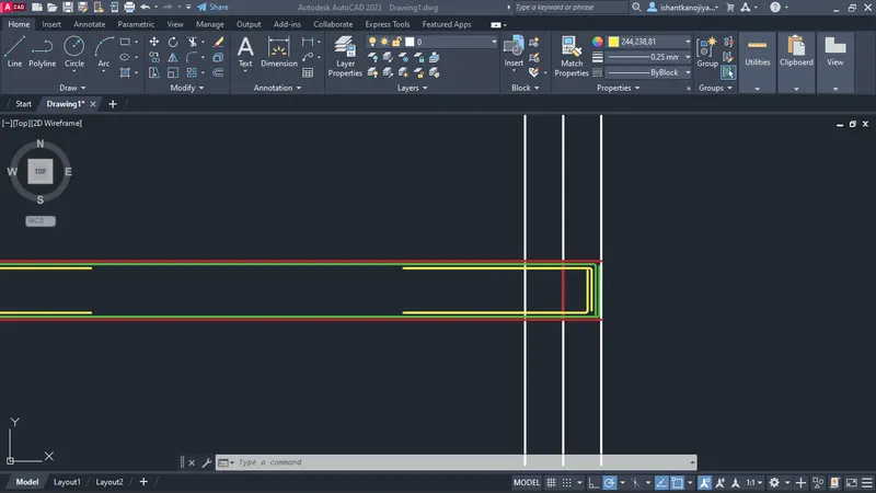
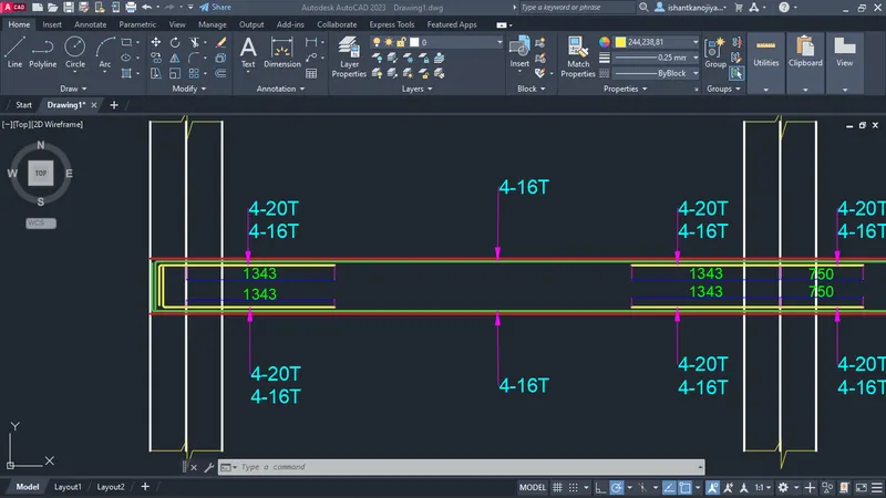
Next, Provide details of longitudinal and shear reinforcement for the two continuous beams. Sketch the beam elevation details or draft it using AutoCAD software.
Procedure:
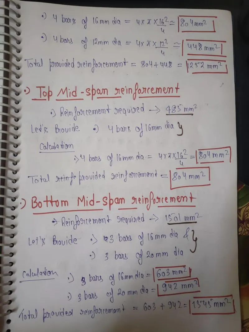
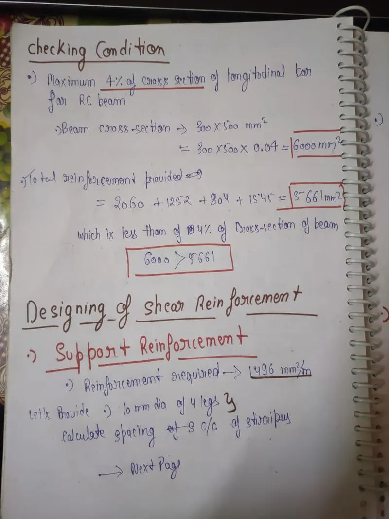
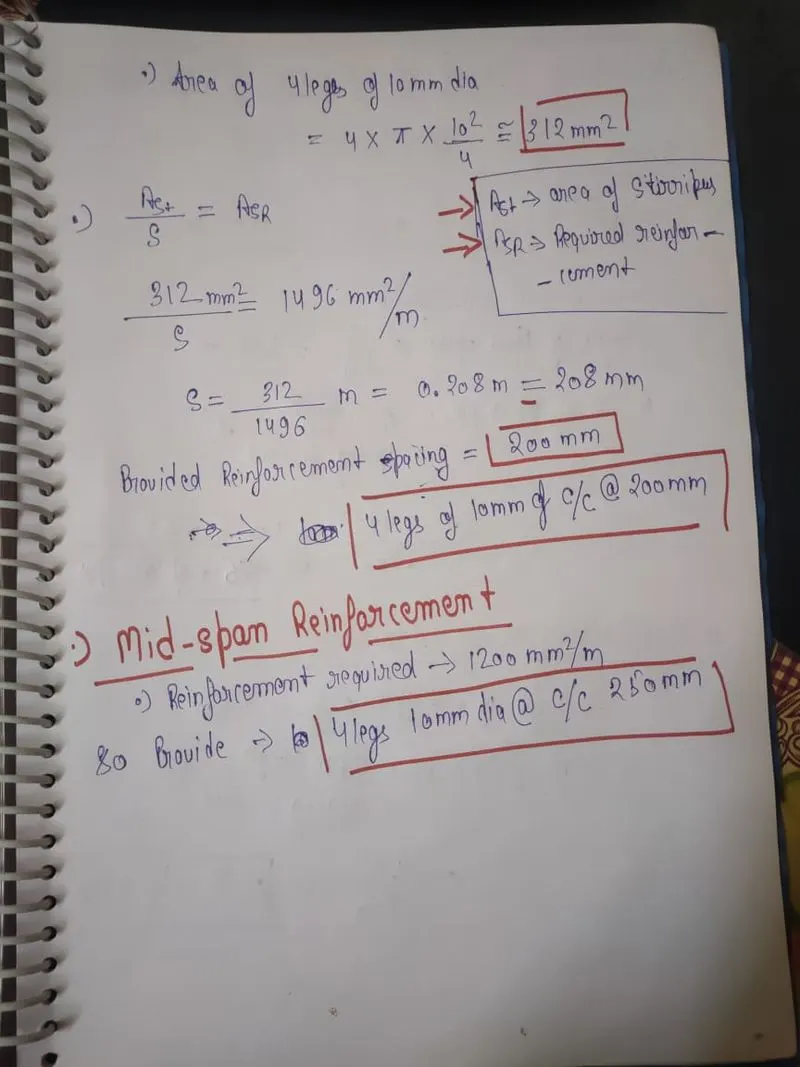
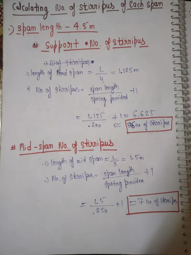
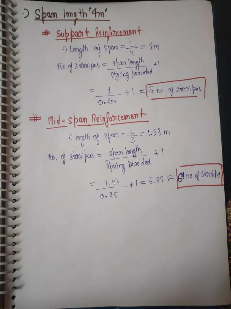
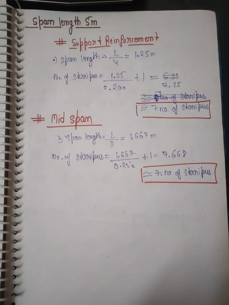
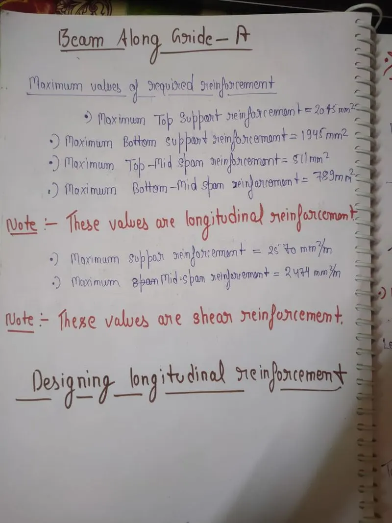
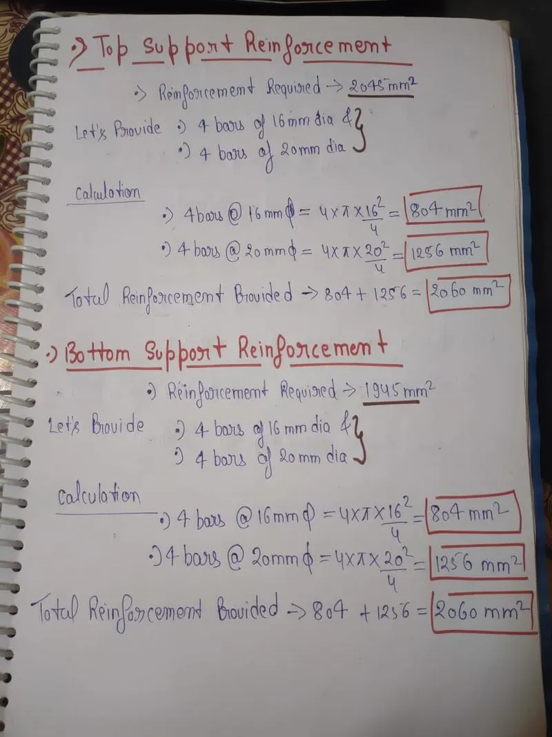
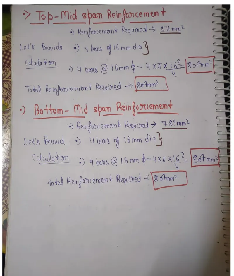
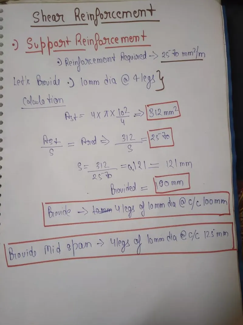
Designing on AutoCAD
Reference of IS-456:2000 and IS-1893:2016 and These images
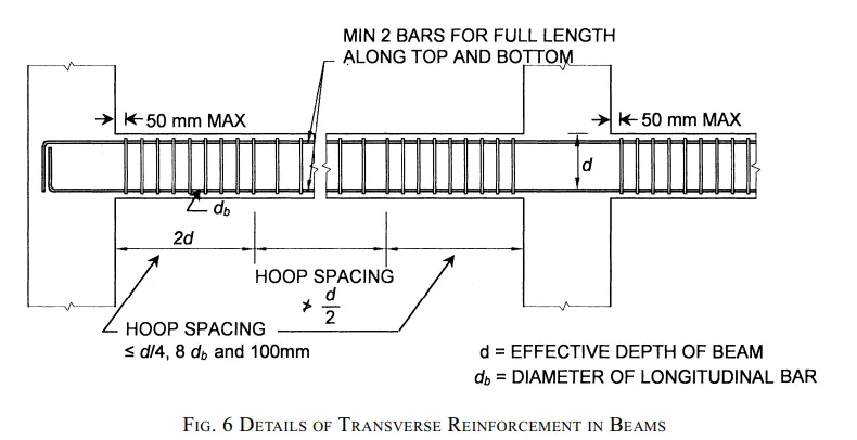
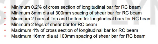
Beam Along Gride-3
-
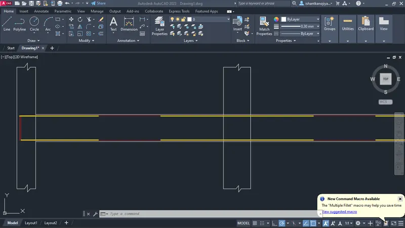
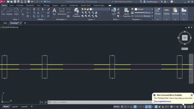
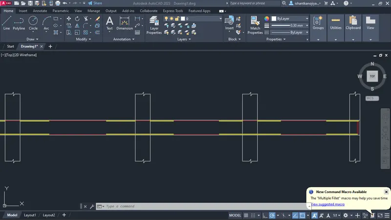
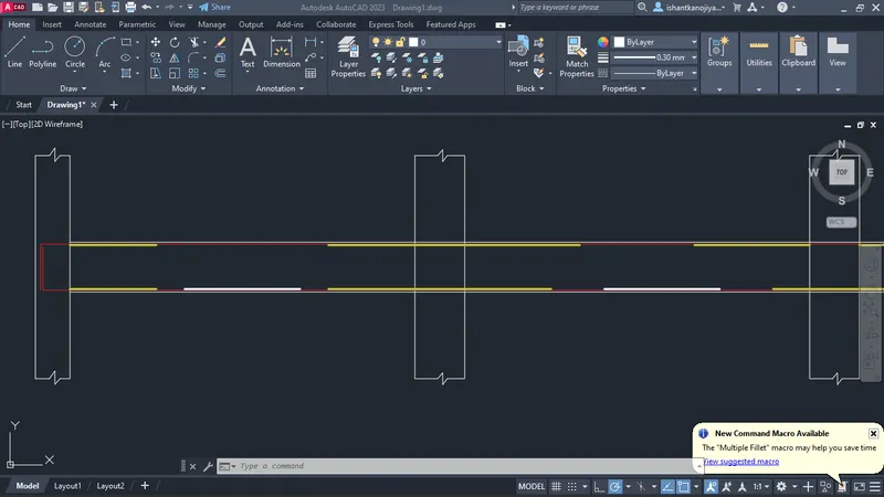
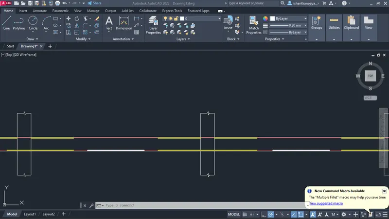
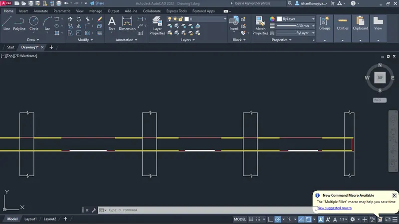
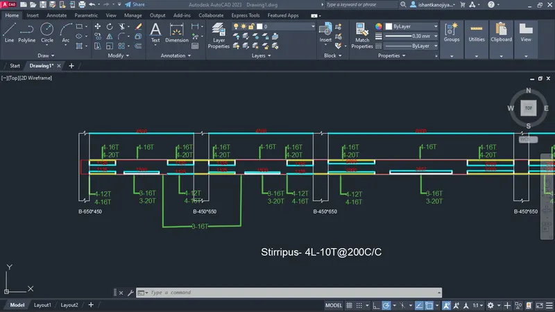
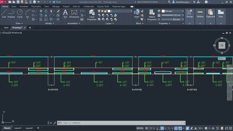 B-450*650 is denoting Cloumn Dimension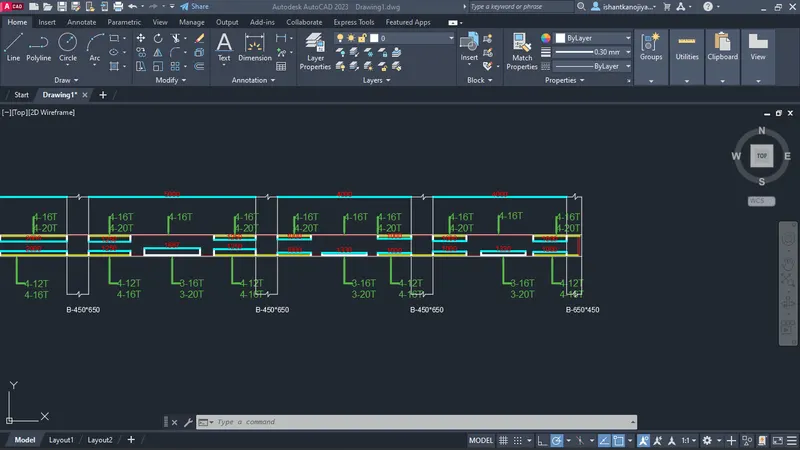
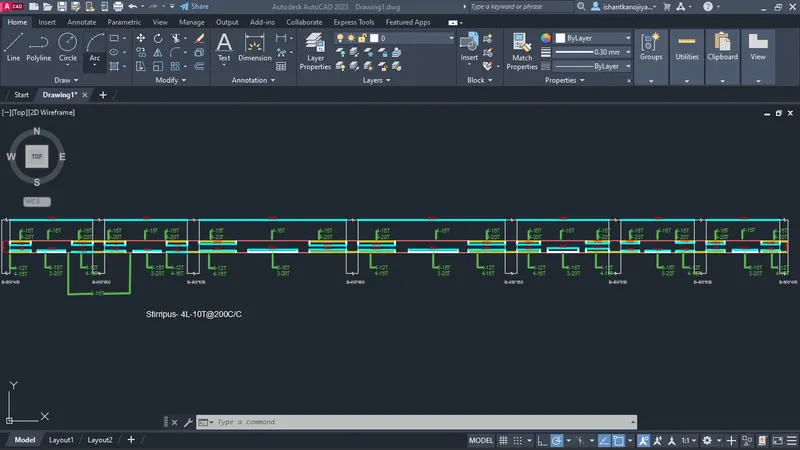
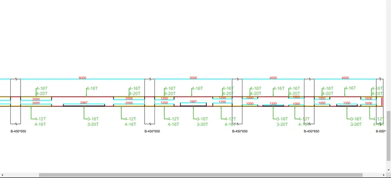
Beam Along gride-A
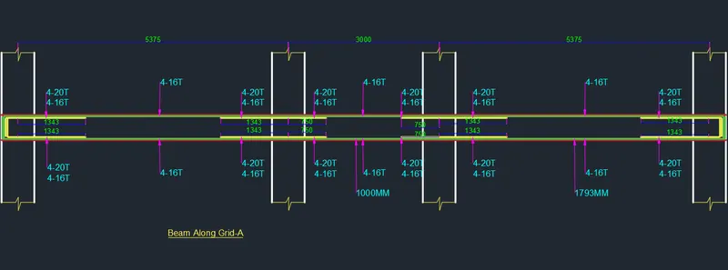
Result:-
2). Provide reasons for the failure of the middle span along grid A. What are the possible ways this issue can be resolved?
Aim:- To determine the Failure of the middle span and Possible ways to resolve it.
Introduction:- Along Gride-A we see the middle span is Over-stressed as below shown in the figure.
Procedure:-
- First Select Beam Right click > Goto detial> goto Shear
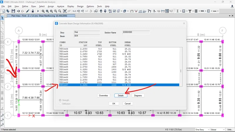
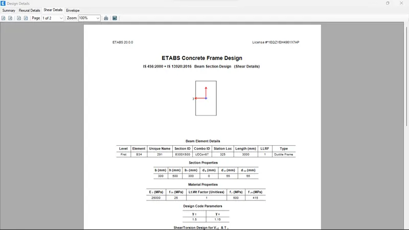
- Goto to the bottom and see the notice
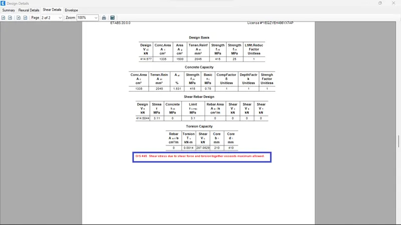
- Notice is Shear stress due to shear force and torsion together exceed maximum allowed
- let's check the values of shear force and torsion
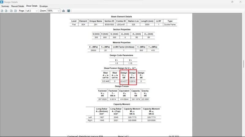
- The shear design value is very high but as we see torsion value is very less(that is the reason the beam is failing)
- so maybe because of the higher shear value beam will fail
- and torsion value is also very less as compared to the shear value.
Suggestions / Result:-
- First, we reduce the loading or increase the loading.
- If we increase the grade of concrete so we increase the shear capacity to avoid the failure of the beam. (Provide M30)
3). Calculate the value of the maximum shear force in any one of the spans in both the continuous beams, as per clause 6.3.3 (b) in IS 13920 – 2016. Also, confirm these values from the shear force demand calculated by ETABS. Please note that if longitudinal reinforcement provided is more than required (as per ETABS results), the shear force demand will vary from what is provided by ETABS.
Aim:- To calculate the maximum shear force as per clause 6.3.3 (b) in IS 13920 – 2016 and confirm these values from shear force demand calculated by ETABS
Introduction:- In this, we Calculate the value of the maximum shear force in any beam by obtaining the value of the Etabs model
We calculate the Right and Left Sway Shear force using IS-1893:2016.
Procedure:-
- First goto Etabs File and Add New Load combination for sway force
- Goto to Define > Select define load combination> Add new combo
- Select D.L-1.2 factor + L.L -1.2 factor + Florr Finishe-1.2 factor + Brick load-1.2 > Press ok > press ok
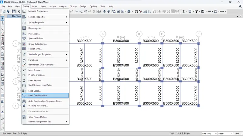
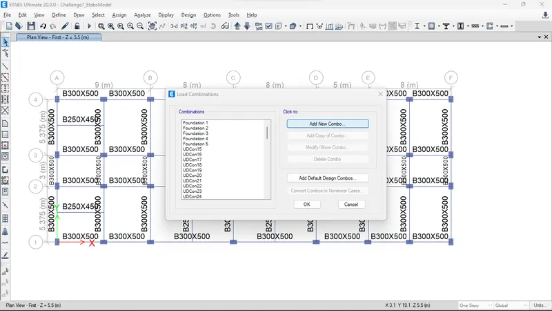
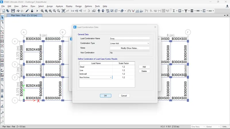
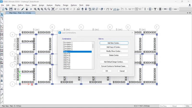
- Then Run Analysis
- Select the Concrete framing design
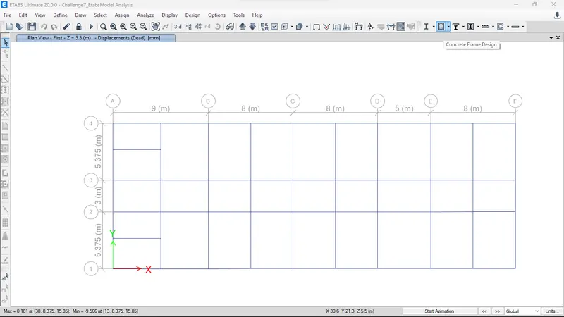
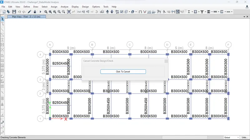
- Then goto Display frame
- select sway combo> select shear 2-2> press apply
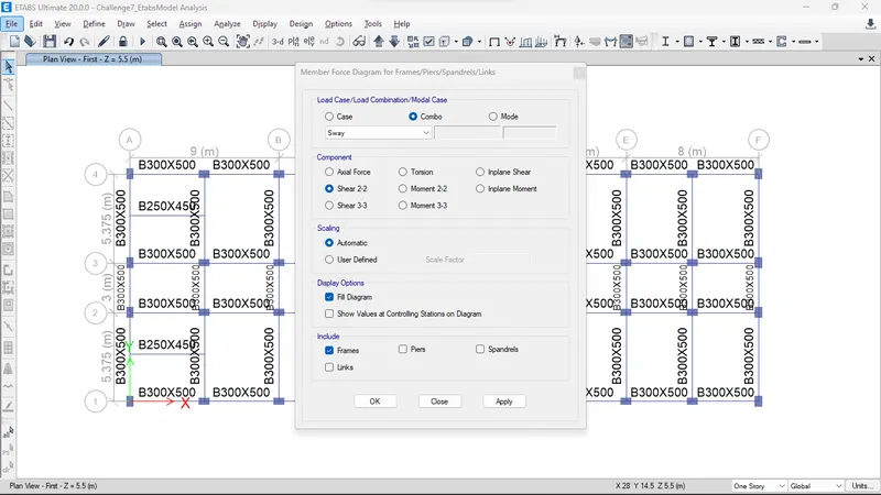
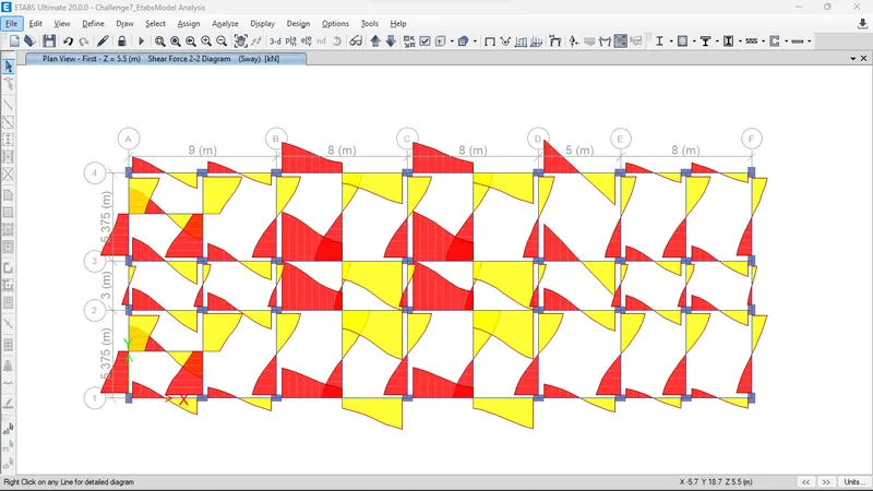
Select Beam no.-70
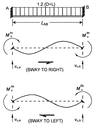
- Taking Values of
 and
and 
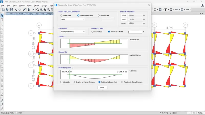
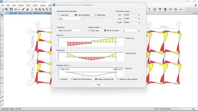
- Taking values of
 ,
, ,
, and
and 
- And
 value is 8m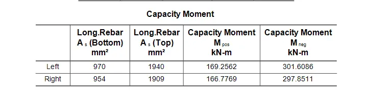
Calculation of shear force
- Right sway shear force
- Formula is
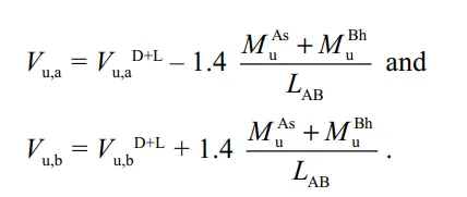
- = 108.5 KN
- = 107.5 KN
- = 169.25 KN-M
 = 297.85 KN-M
- = 8 M
 = 108.5 - 1.4*(169.25 + 297.85)/8 = 26.75 KN.
 = 107.5 + 1.4*(169.25 + 297.85)/8 = 189.24 KN.
- Left sway shear force
- Formula is
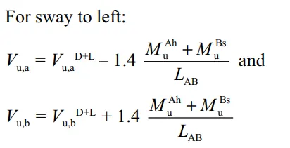
- = 108.5 KN
- = 107.5 KN
- = 301.60 KN-M
- = 16.77 KN-M
- = 8M
= 108.5 - 1.4*(301.60 + 166.77)/8 = 26.54 KN.
= 107.5 + 1.4*(301.60 + 166.77)/8 = 189.46 KN.
Result:-
Right Sway Shear force
= 26.75 KN.
= 189.24 KN.
Left Sway Shear force
= 26.54 KN.
= 189.46 KN.