Radar Mast & Final Assembly of Yacht
1. Radar Mast
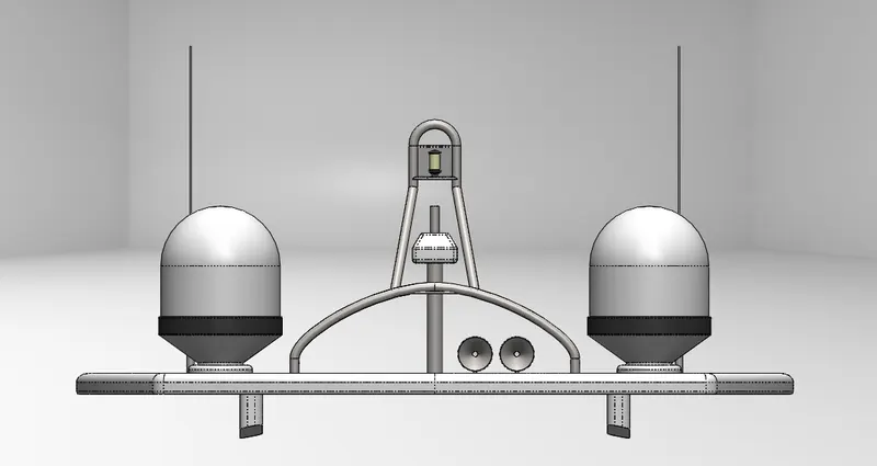
- Front view
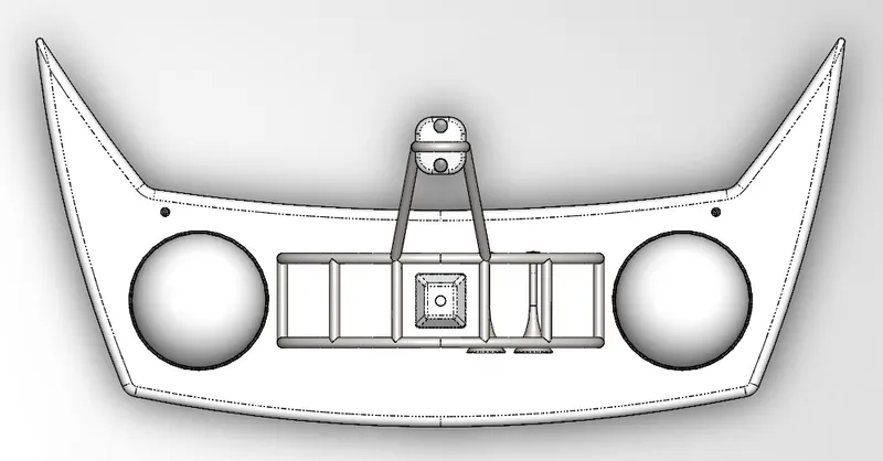
- Top view
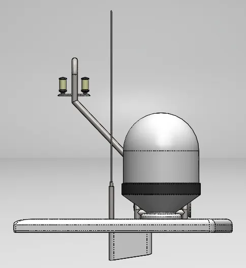
- Side view
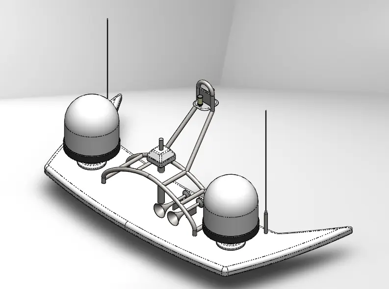
- Isometric View
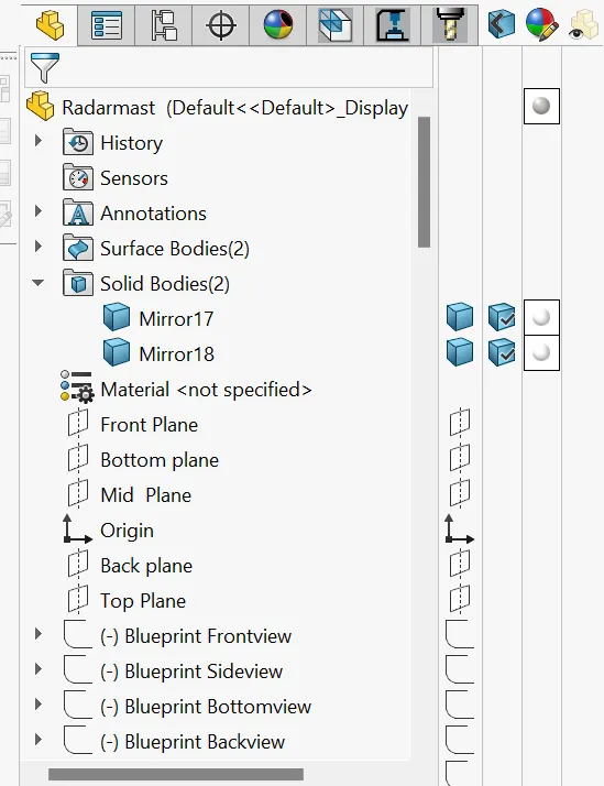
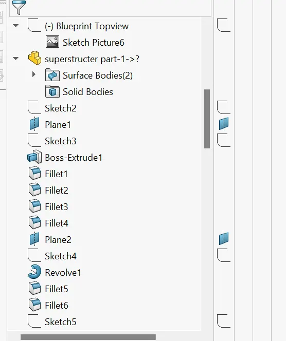
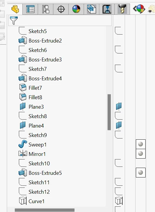
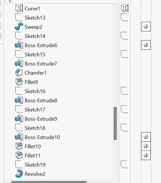
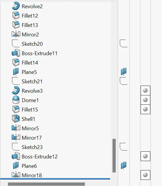
- Feature Tree for Radar mast
2. Yacht Assembly
Project Report
- Modeling of a Sunseeker Predator Yacht
- Modeling and assembly of Sunseeker Predator Yacht In Solidworks
- All these components are made by using Solidwork software only
Objective:
- Learning how the blueprint is used to make the required modal
- To Understand surface modeling and sheetmetal modaling indetail
- To understand curve projection to make complicated surfaces
- To understand Time-saving for modeling by using the mirror feature
- Understanding step-by-step assembly by arresting the degree of freedom of parts
- Making render in Photoview 360 and understanding Decals, environment, Lighting, Camera, Appearance, etc...To make a realistic appearance.
- Doing rendering To make a realistic appearance of a modal using photo view 360 and Solidworks visualization.
Introduction
In this project Modeling different components of a Sunseeker Predator Yacht. and made them Assemble by using the Solidworks tool. In this design project, Firstly, we learn about each command and apply it one by one to create each part. Initially, the blueprint is set up for a base plan to take a reference for every part we get the knowledge about 2D & 3D sketching and dimensioning the parts. After designing the parts, we study assembling each part to create the, All the Components are designed individually and Mateing them together by Fixing Some Geometrical constants And making the whole Assembly. the following parts made They Are.
- Propeller
- Radar
- Hull
- Garage door
- Front seat
- Rear Seat
- Middle seat
- Superstructure
- Radar mast
Design Approach
- There are two types of a design approach
- Top Down Approach &
- Bottom-Up Approach
- Top Down Approach: One or more features of a part are defined by something in an assembly, such as a layout sketch or the geometry of another part. The design intent comes from the top, which is the assembly, and moves down to the parts.
- Bottom-Up Approach: You first design and model parts, then insert them into an assembly and use mates to position the parts. To change the parts, you must edit them individually. These changes are then seen in the assembly.
- Here we have used Bottom Up Approach because it is the simplest method for creating an assembly.
Design methodology Flowcharts
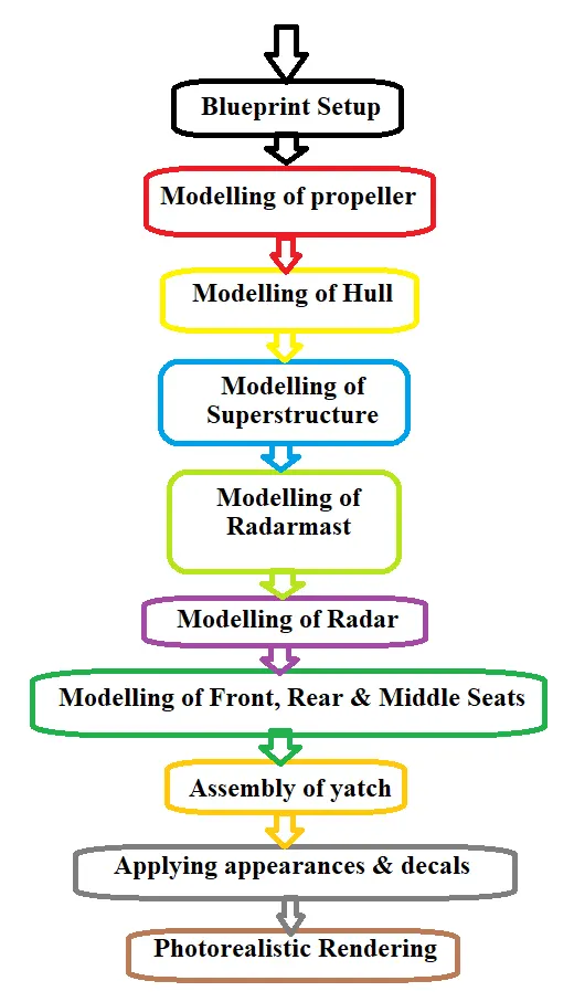
Description: Here is the procedure followed to create this project.
The following Tools/Features used to create the modal are
1. Sketching Drawing the 2D or 3D sketches and making dimensions for the sketch and applying geometrical relations.
2. Features: Choose the Required Suitable features such as revolve, extrudes, and fillets, and determine features to apply.
3. Surfaces: Surfaces are Generated by applying various surface features like extrude, extend, trim, knit, etc.
4. Assembly: All the components are mate together by fixing the X, Y, and Z axis.
Detain description of tools which we used to modal the yacht are given by Billow
1. Sketch Commands:
- 2D Sketch- Firstly 2d sketch is created on a required plane To make it 3 dimensional Part Every modal Dipens up on the sketch, and we can create features. like, extrude revolve, etc...We can add delete or combine one or more features to make a part. Then, we can mate the appropriate parts to create an assembly. From the parts or assemblies, complete drawings are created.
- 3D sketch- When sketching in 3D, we can snap to directions X, Y, and Z, and constraints are applied Along X, Y, and Z respectively. When sketching on a plane, we can snap to the horizontal or vertical directions in the plane, and constraints are applied to the Horizontal and the Vertical.
- Smart Dimension- Creates a geometrical dimension for any selected sketch entity.
- Point– It is a 1Dimenction element, it inserts a point or vertex into a sketch entity. This cannot be deleted if it is part of the sketch endpoint or center point.
- Line- A line has one endpoint Line is one of the first sketching tools, lines can be drawn horizontally, vertically, or at any angle. It plays a very important role to complete the 2D drawing of the product or part.
- Circle- The circle enables to create the circular drawing on the graphics area. There are two circle tools available and they are the “Centre circle” and “Perimeter circle”.
- Rectangle- Sketches rectangles or squares with a center point at a selected angle there are rectangles like centered rectangles, and corner rectangles. Parallelogram sketches a standard parallelogram.
- Spline– splines can be created with several midpoints depending on the complexity of the curve. A 2 or 3-dimensional curve defined by a set of control points. Points within a spline can be added or deleted.
- Sketch Fillet- A tangent arc in between two sketch entities can be created with a radius.
- Text- It can be used to write the text necessary wherever required whether it’s a plane or the face of a model.
- Convert Entities- Copy a sketch entity on a plane, it must have an original sketch entity already drawn and selected to use this tool.
- Offset Entities– Creates a sketch entity to a specified distance from the original entity. Must have an original sketch entity already drawn and selected to use this tool.
- Sketch Picture- Insert an image file into the background of a sketch. This allows the user to 2D sketches based on the image. Use the sketch picture property manager to alter the inserted image.
- Mirror Entities-The following sketch can project the opposite Concerning the Selecter line.
- Trim & Extend- Created sketches can be get erased or filled by using the trim and extend tool.
- Sketch Pattern- selected sketch can be projected a required given number of times by giving directions and distances.
Featur Commands
Some sketch-based features are shapes such as extrude, extrude-cut, and holes. Other sketch-based features such as lofts and sweeps use a profile along a path. Applied features include fillets, chamfers, or shells they are applied to existing geometry using dimensions and other characteristics to create the feature. Then we add applied features. It is possible to create a part without sketch-based features.
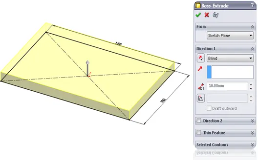
Extruded Boss/Base - An Extruded Boss/Base feature will allow us to take a 2D sketch and add thickness to it in the perpendicular dimension.
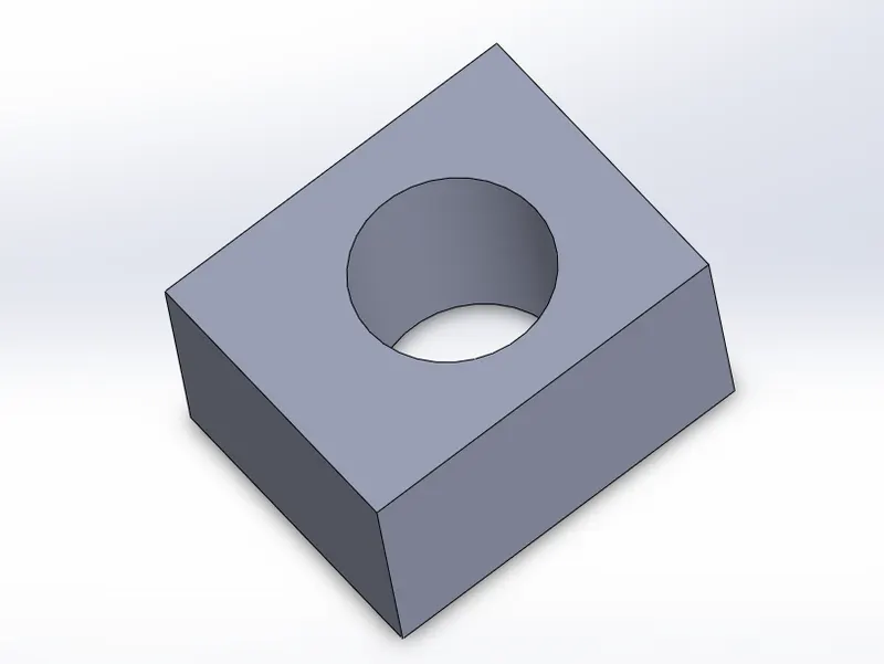
Extruded Cut – It is a tool to remove material by projecting a sketched section normal to the sketch plane.
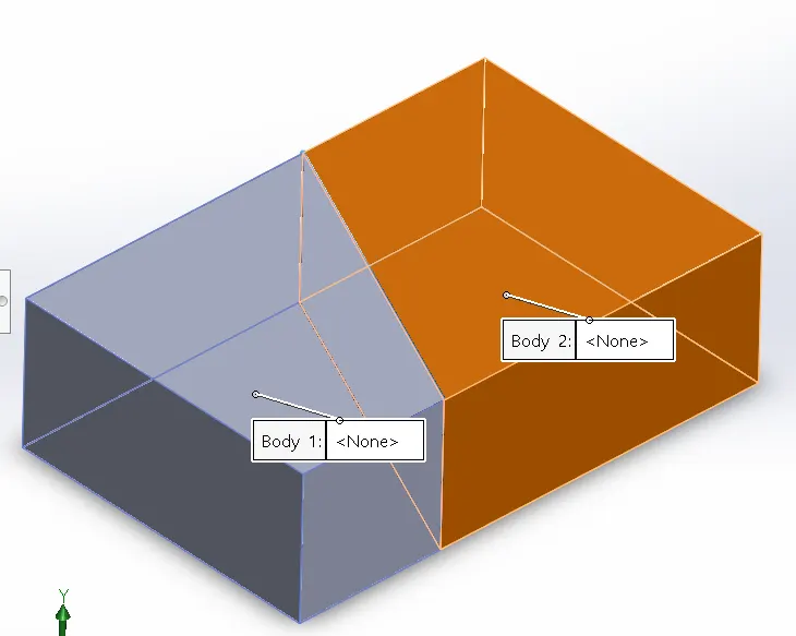
Split - Lines are used to dividing model faces into two. Split lines are created like any other sketched planes and the projected part going to be split.
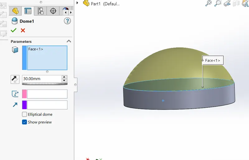
Dome – dome can be of two types elliptical and spherical. It can add one or more domes to the selected planar or non-planar faces. The software calculates the distance using the radius of the arc as a basis for the dome.
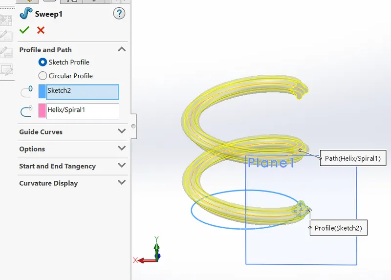
Sweep: the sweep feature is used to make the sketch flow along the spline path, the sketch may be any shape example circle rectangle, or line that will follow the spline helix.
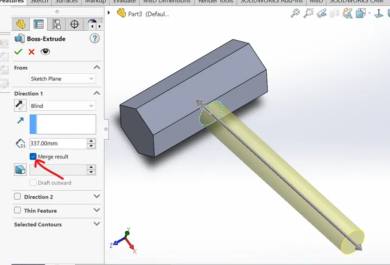
Merge – combines solids or surfaces directly as a single solid or surface by selecting merge reasult opction on an every boss-extrude
3.Surface Modelling
surface modeling is known as zero thickness geometry, Surface modelling is a method of creating planar or non-planar complex geometry which has zero or negligible thickness. The surfaces are generally used to create models of complex shapes. We can convert surface models into solid models. We can also extract a surface from a solid model using the tools available for surface modelling.
Surface Commands:
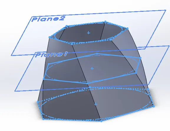
- Lofted Surfaces – the lofted surface is created between two or more profiles or sketches. Specify start and end constraints and add guide curves to specify the path shape.
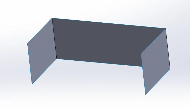
- Extruded Surfaces –A sketch or selected sketch contours in one or two directions two create surface features.
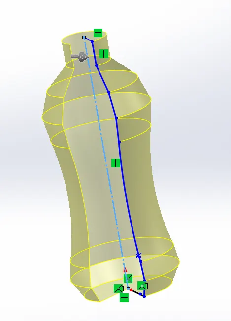
- Revolved Surfaces – Revolves a sketch or selected sketch contours around an axis to create revolved surface features.
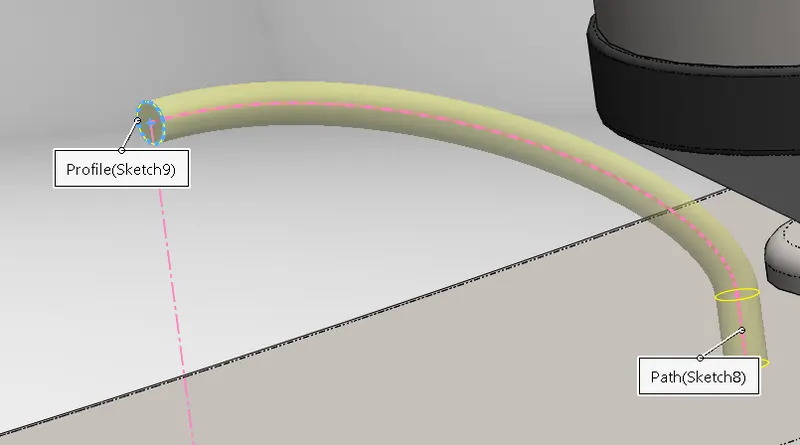
- Swept Surfaces – It Sweeps a closed profile along an open or closed path to create a surface feature. It uses a tangent plane at the end of the path so that the path is normal to the swept surface to create a sketch.
- Filled Surfaces – The filled surface is used to create the face by selecting the edges as a boundary
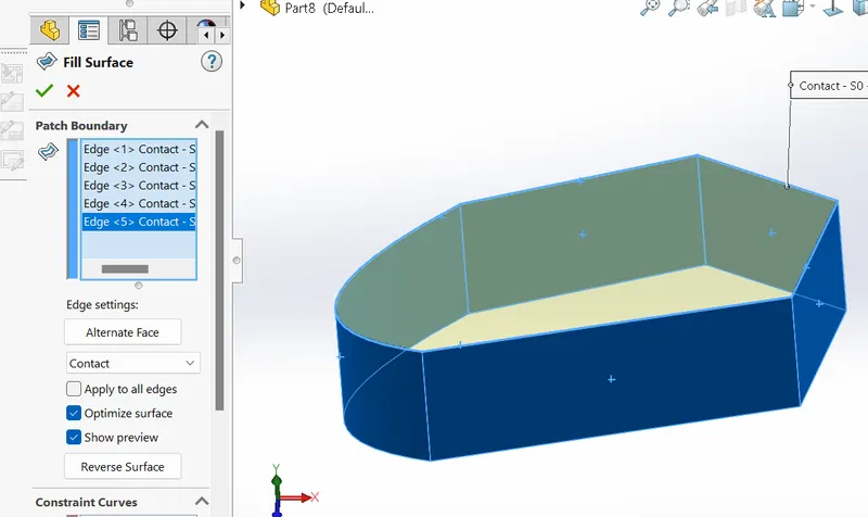
- Ruled Surfaces – Inserts ruled surfaces in a specified direction from edges. Tangent to the surface, Normal to the surface, tapered to vector, perpendicular to vector, or sweep can be selected.
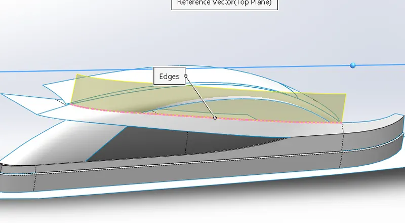
- Trim Surface – It trims the surfaces where a surface intersects with another surface, by a plane or a sketch.
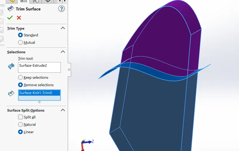
- Knit Surface – It combines two or more adjacent, non-intersecting surfaces into a single surface body.
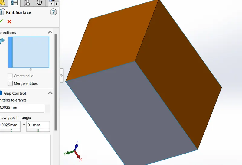
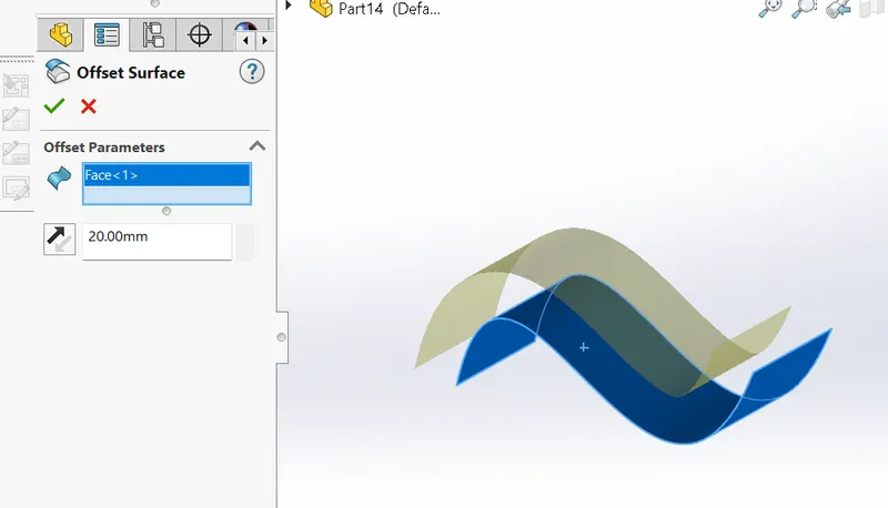
- Offset Surface – Offset surfaces using one or more continuous faces. This tool helps us to create an offset surface with required gaps.
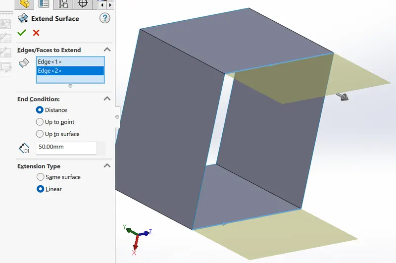
- Extend Surface – This feature can Extend one or more edges or faces on a surface, based on end conditions.
- Mirror surfaces – A mirror feature is used to project the same surface into the opposite side with the same dimensions, mirrored about a plane or planar face. A mirror sketch entity is a copy of a selected sketch entity that is mirrored about a centreline. If the original feature or sketch is modified, the mirrored copy is updated to reflect the chage.
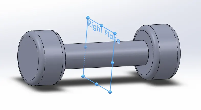
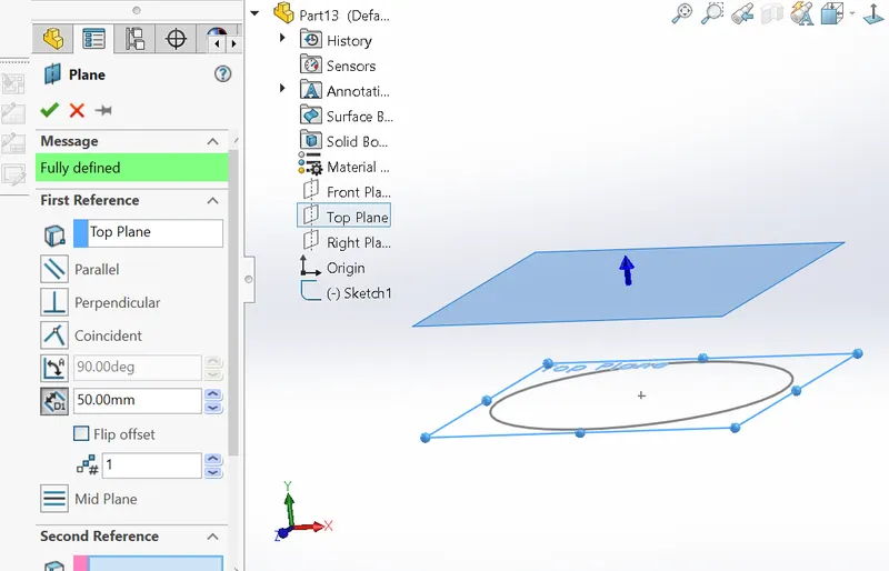
- Reference plane – Planes can be created in part or assembly documents. We can use planes to sketch, create a section view of a model, for a neutral plane in a draft feature, and so on.
Projected curve – A projected curve is typically used either in sweeps and lofts as the path or guide curve.
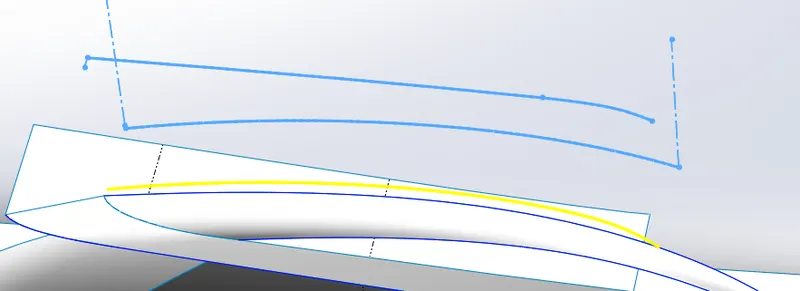
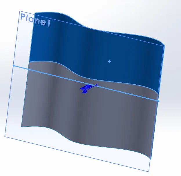
- There are two types of curve projections
- Sketch on Sketch: Use two sketches to make a single curve
- Sketch on the surface: Use a sketch to project on a surface
- Modeling:
The yacht consists of the following parts to be designed individually and assembled.
1. Blueprint- It is set up using respect to reference planes where 2D and 3D sketches are drawn with transparent blueprint photos.
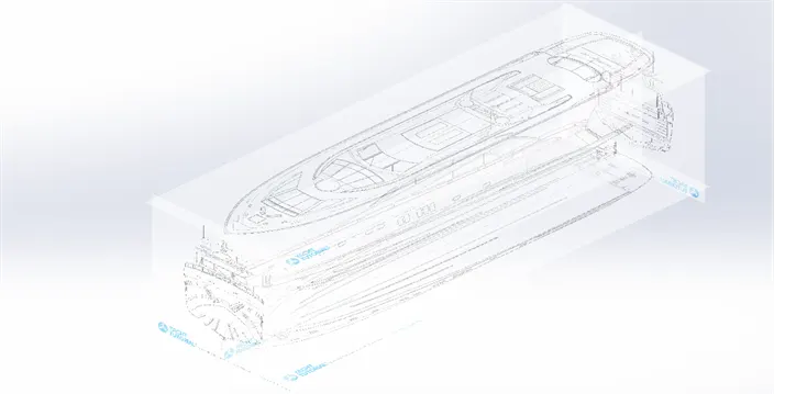
Fig1: Blueprint setup
2. Hull - Hull is the base for all other parts in the assembly, accommodating all other parts.
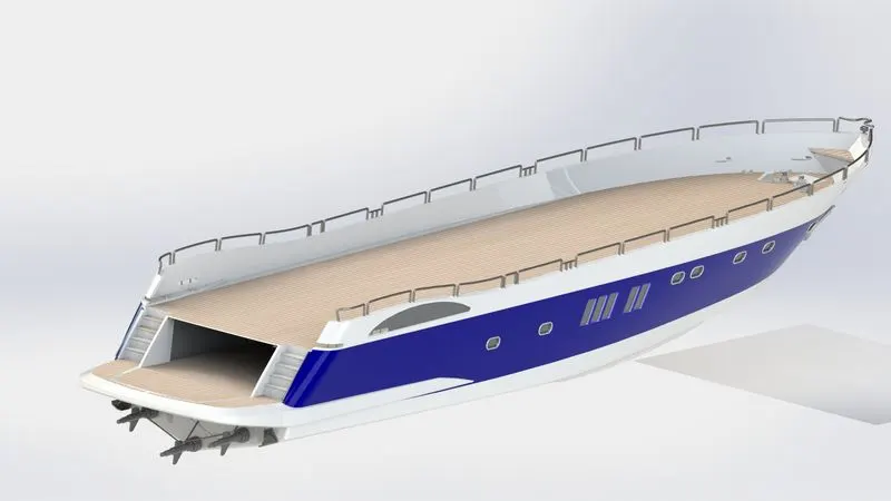
Fig2: Hull
The following features which I used to create the Hull modal are
- Cure projection
- surface loft
- surface trim
- Surface extrude
- Surface knit
- Surface fill
- Shell
- Boss extrude
- Cut extrude
- Fillet
- Chamfer
- sweep
- New plane
- Revolve
- Dome
- Helix
- Linear pattern
- 3D sketch
- Mirror
- Split Body, Split line
- Adding decals
3. Superstructure - The superstructure-upper position of the Hull was Designed by surface modeling to create aerodynamic Structures.
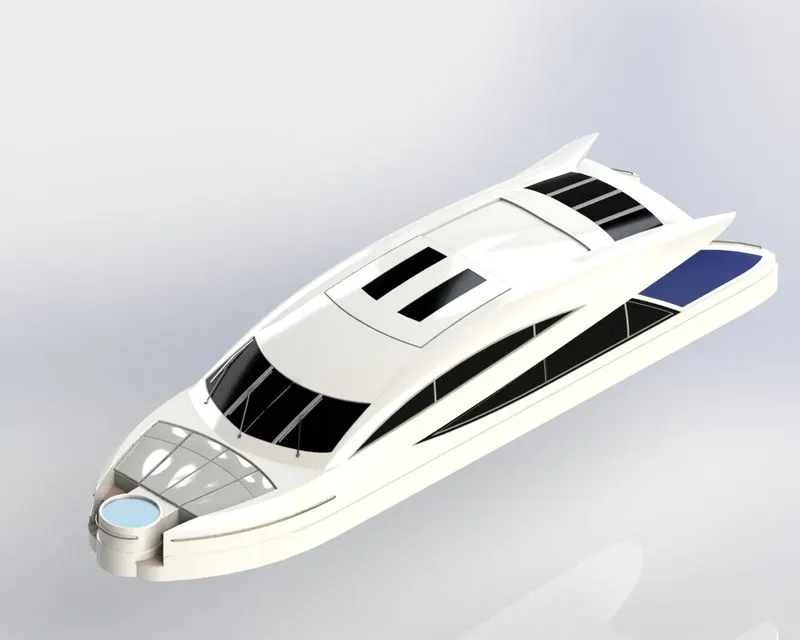
Fig3: Superstructure
The following features which I used to create the Superstructure modal are
- Surface extrude
- New Plane
- Surface sweep
- Surface Knit
- Fillet
- Surface Trim
- Loft surface
- Surface fill
- Ruled surface
- 3d sketch
- Surface extend
- Boss Extrude
- Cut Extrude
- Delete face
- Add thicken
- Dom Face
- Split line
4. Propeller - Revolve and circular pattern features are used to create this modal
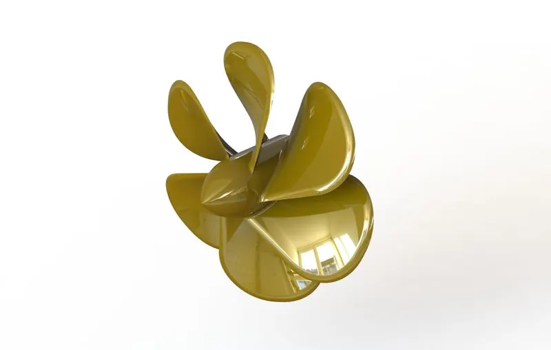
Fig4: Propeller
The following features which I used to create the Propeller modal are
- Revolve
- Loft
- Fillet
- Cut extrude
- Circular pattern
5. Garage Door - Removing the material and Annotation feature is used to create this modal
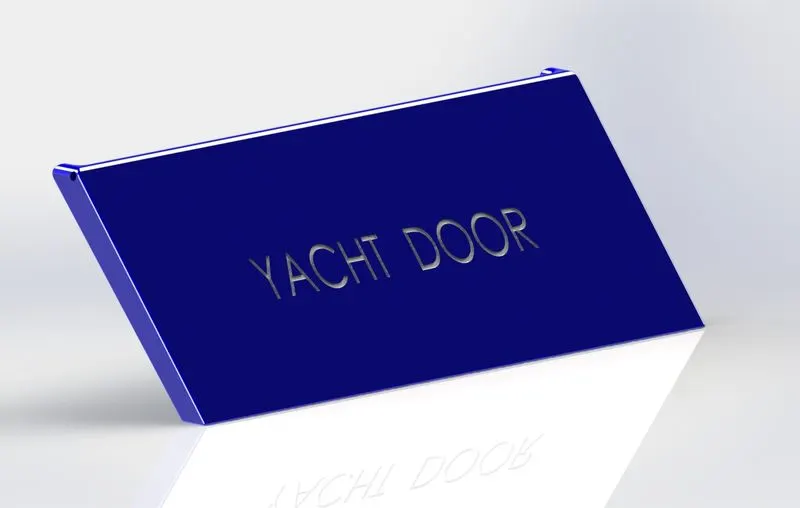
Fig5: Garage Door
The following features which I used to create the Garage Door modal are
- Boss Extrude
- Cut Etrude
- Shell
- Fillet
- Cut Extrude
- Mirror
- New Plane
6 .Radar-
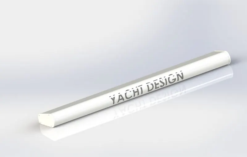
Fig6: Radar
The following features which I used to create the Radar modal are
- Boss Extrude
- Fillet
- Cut Extrude
- Sketch Pattern
- Mirror
- Split Line
7. Radarmast -
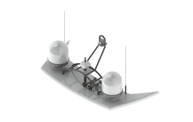
Fig7: Radarmast
The following features that I used to create the Radarmast modal are
- Insert surface body
- Boss extrude
- Fillet
- Plane
- 3dSketch
- Mirror
- Curve Projection
- Sweep
- Revolve
- Dome
- Shell
8. Front seat -
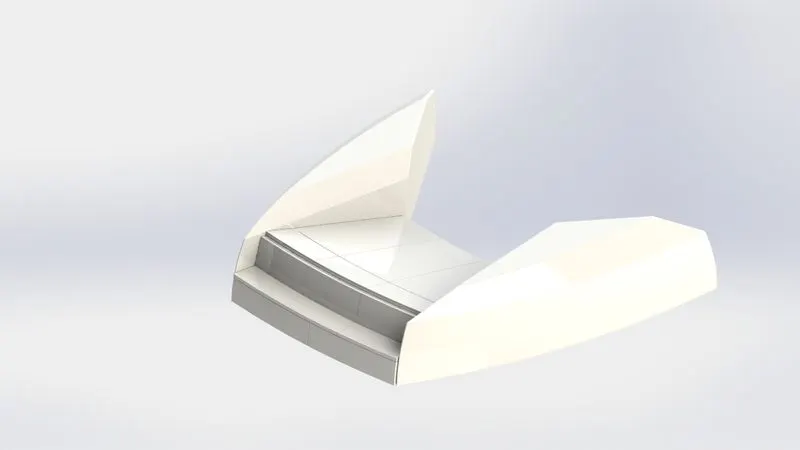
Fig8: Front seat
The following features that I used to create the Front seat modal are.
- import surface body
- Plane
- Surface sweep
- Surface Trim
- Surface Fill
- Surface Loft
- Surface knit
- Chamfer
- Revolve
- Mirror
9. Midil seat -
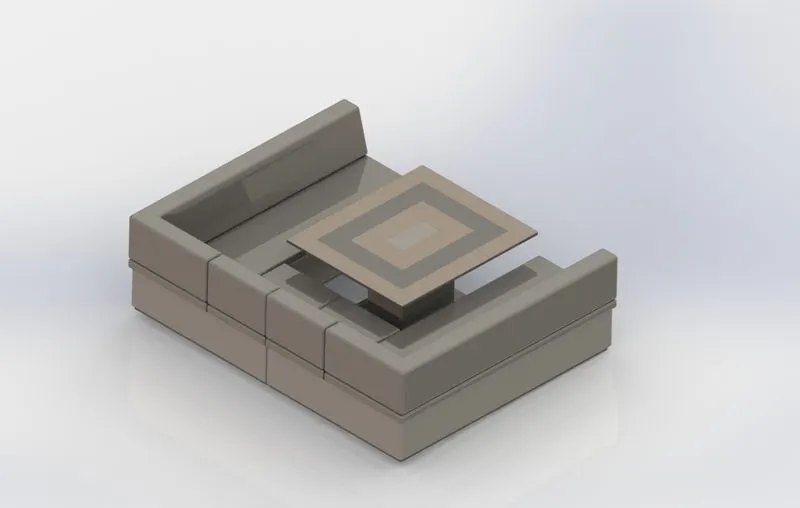
Fig9: Midil seat
The following features that I used to create the Midil seat modal are.
- Boss extrude
- New plane
- Chamfer
- Fillet
- Mirror
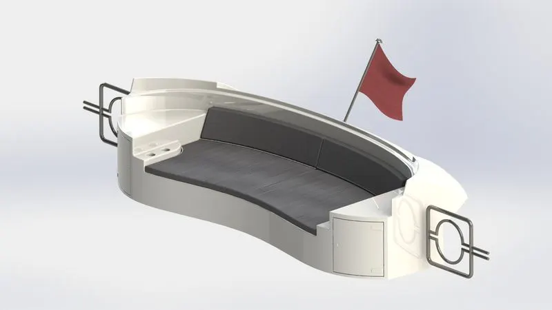
10. Rear seat
 -
-
Fig10: Rear seat
The following features that I used to create the Midil seat modal are.
- New Plane
- Surface sweep
- Surface Offset
- Surface Trim
- Surface Extend
- Surface Knite
- Surface Loft
- Boss extrude
- Cut Extrude
- Surface Trim
- Revolve
- Fillet
- Chamfer
11. Front view -
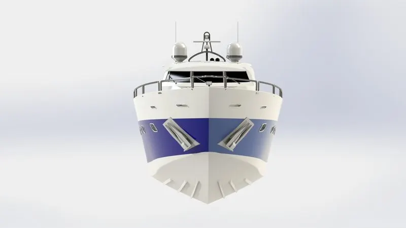
Fig11: Front view
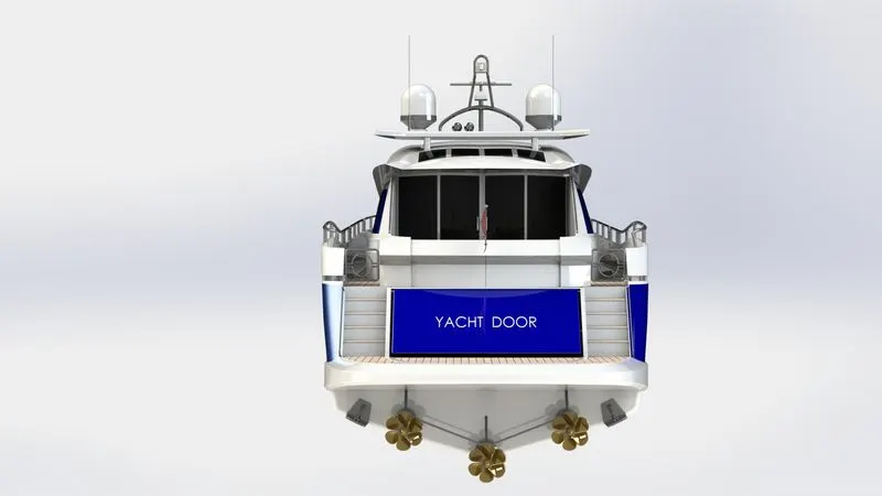
12. Back view
 -
-
Fig12: Back view
13. Side view -
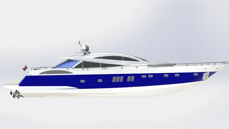
Fig13: Side view
14. Top view -
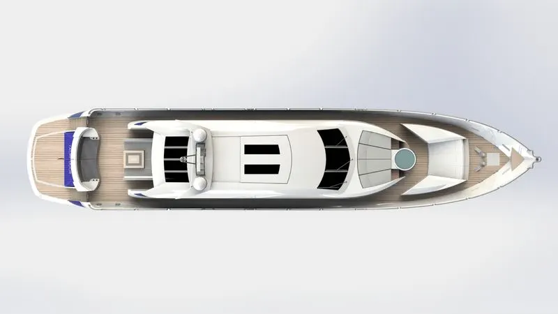
Fig14: Top view
15.Camara view -
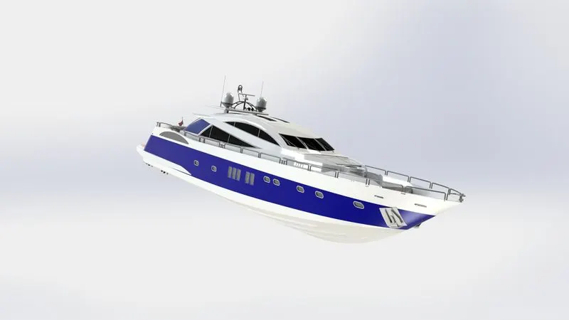
Fig15:Camara view
16. Isometric view -
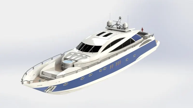
Fig16: Isometric view
RENDERED IMAGES OF SUNSEEKER PREDATOR YACHT
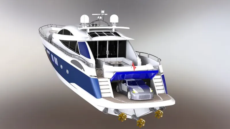
Fig17: Rendered view(a)
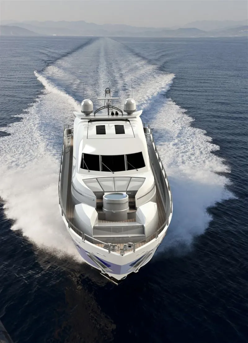
Fig18: Rendered view(b)
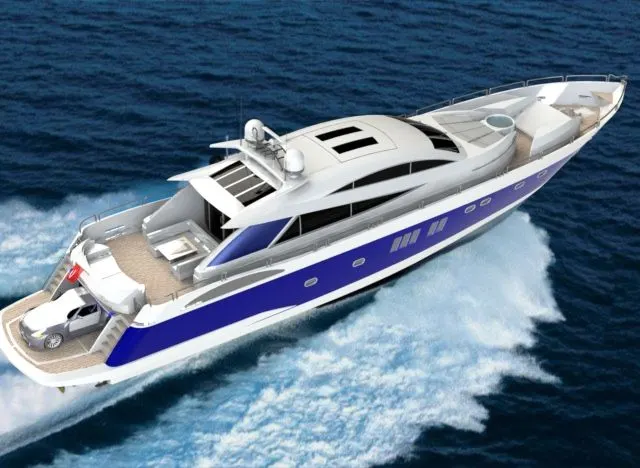
Fig19: Rendered view(c)
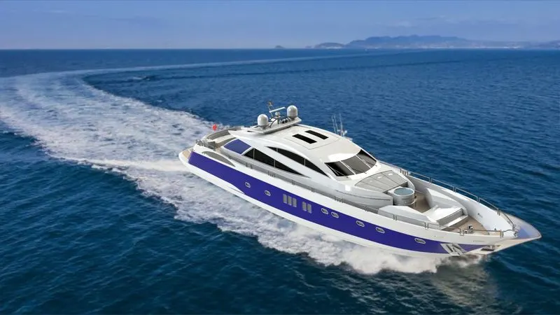
Fig20: Rendered view(d)
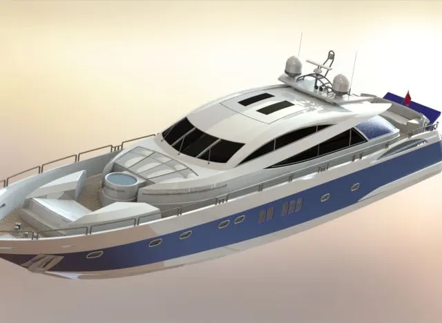
Fig21: Rendered view(e)
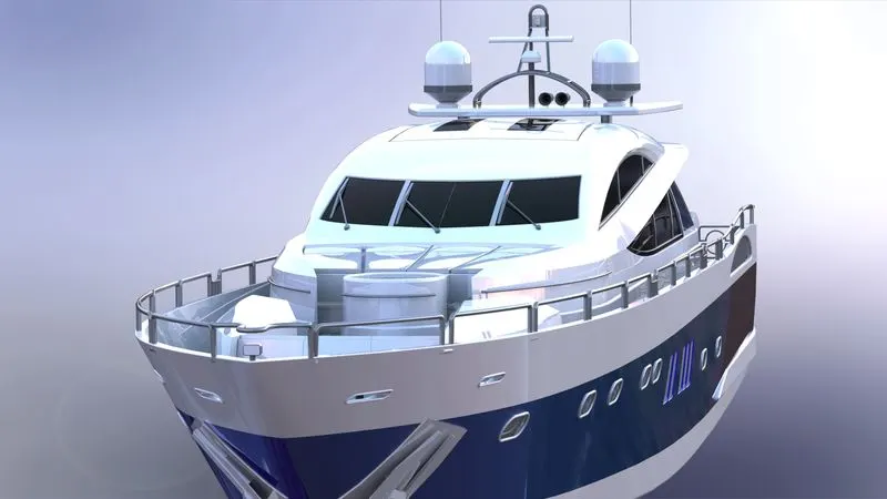
Fig22: Rendered view(f)
Conclusion: Hence the Sunscreen predator yacht has been modeled and rendered using Solidworks design software.