Photo Realistic Rendering
....MODELLING OF AMERICON CHOPPER USING SOLIDWORKS....
- Objective
- To know about each and every command in SOLIDWORKS.
- Designe every part of the chopper using commands.
- Make assembly of the chopper by all of the chopper parts .
- Make Rendering of the chopper using photo view 360 and solidworks visualizetion tool.
- Introduction:
In this Project, we learnt about design and Modeling of AMERICAN CHOPPER using SOLIDWORKS Tool. Firstly we need to learn about every commands and using those command we have to bult the different parts of a chopper. And each part has various steps and commands to designe the modal. After designing the all different parts of the chopper we need to learn how to assembly the chopper using different types of mates to adjest the digri of freedom of each parts and place it on the proper position to get apropriorate shape. After creating the assembly of the chopper We study about rendering of the model using photo view 360 and solid works visualizetion.
3. Design methodology:
Flowchart
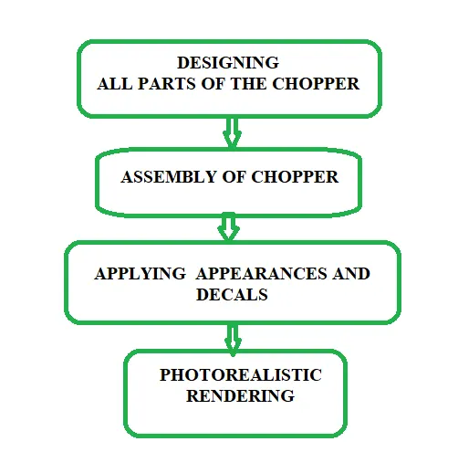
Types Of Approaches:
There are mainly two types of approaches are used in assembly .One is Top down assembly and the other One is bottom up assembly.
⦁ Top Down Assembly
Top-down assembly modeling is an assembly-centric method, which starts at the highest level possible and individual parts and sub-assemblies are defined within the context of the overall assembly.
In top down assembly we start with an assembly and then design the parts in the assembly workbenchand then give constraints between different parts.This allows the use of other parts features to model another part.So the geometries from other parts can be used as a Reference.
⦁ Bottom up assembly
In bottom up assembly we model each and every part as a single parts and then save them as part files and assemble later in the Assembly module in SolidWorks.In this case if any changes required in the assembly then we have to open the part separately and then change it.
- Both these kinds of assemblies are possible in SolidWorks. Here in this project a bottom up assembly is used.
- So all the parts Below mentioned that are designed separately and saved as part models and then assembled later.
Method : To design a chopper firstly we need to know about the user interface of the SOLIDWORKS. Later on one by one we need to design all the required parts of the chopper.
On Week-1 Transition belt, Kickstand & front fender,
week-2 Rear Fender, Chain, Oil tank & Pedal,
week-3 Front wheel,
week-4 Rear wheel & Front fork,
week-5 Chassis & Engine,
week-6 Gas tank,
After designing all the parts chose an Assembly section and join all the parts by using mates feature & make Final Assembly of the chopper. We can also able to do convert and arrange the assembly files and parts to zip file by using pack and go option After compliting chopper assembly, Render using photo view 360 to get realistic view of the chopper and Environment by adjusting callers, Giving material, Adding decals, Adjusting lights, Creating our won camera views. All this makes our chopper more realistic look.
4. Description:
The aim's to accomplish this project are designing the parts of the chopper and making assembly of all the parts to get a chopper and to make it look better we add decales (stickers) to the chopper which makes it more attractive we add lighting shadows environment which makes chopper looks realistic.
After making the chopper it's time to snap the chopper with good and realistic look for that we use photo view 360 to view in different backgrounds & sceneries & SolidWorks visualization.
1. The following commands & features used to creating the parts of American chopper are..
- Extrude & Extrude cut
- Revolve and Revolve cut
- Swept adn Swept cut
- Lofted Bass/base
- Fillet
- Chamfer
- Linear pattern
- Circular pattern
- Mirrer
- Shell
- Referance Geomentry
- Curve (project & composit)
- Dome
- Split
- Combine
- Boundary Surface
- Knit Surface
- Mates
- Coincident
- Concentric
- Tangent
- Parallel
- Perpendicular
- Distance
- Angle
- Width
- LImit Angle
- New Plane
part 1
Transmission belt
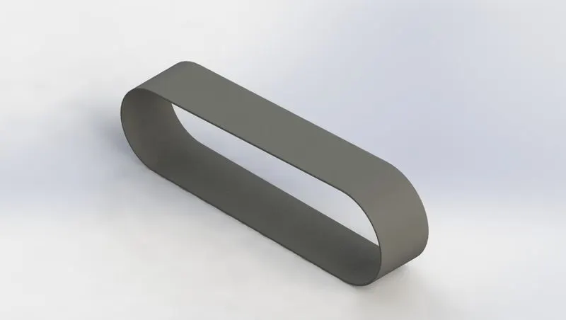
The following Features which i used to creat this part are
- Bose Extrude
- Fillet
- Appearance
part 2
Kickstand
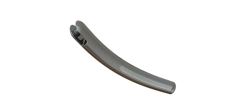
The following Features which i used to creat this part are
- Lofte
- Dome
- Cut Extrude
- Split
- Fillet
- Appearance
part 3
Front fender
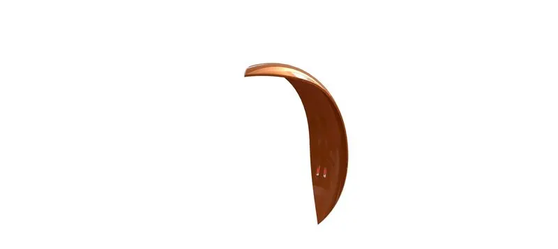
The following Features which i used to creat this part are
- Revolve
- Split
- Fillet
- Appearance
part 4
Rear fender
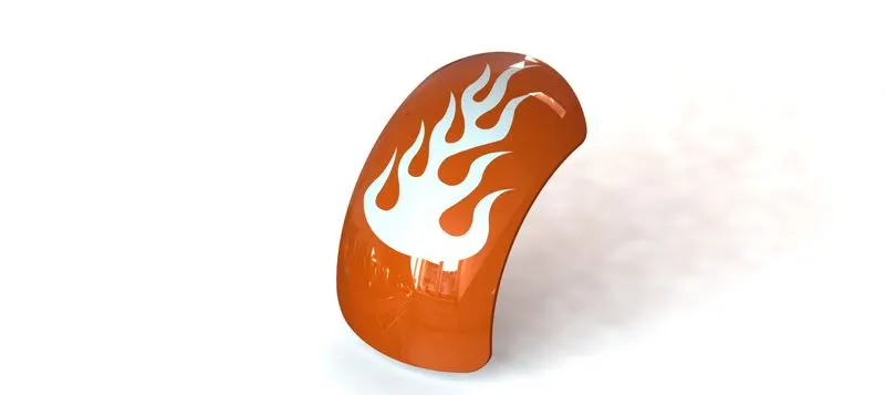
The following Features which i used to creat this part are
- Revolve
- Split
- Fillet
- Shell
- Appearance
part 5
Oil Tank
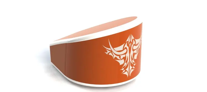
The following Features which i used to creat this part are
- Boss Extrude
- Combine
- Fillet
- Shell
- Appearance
part 6
Stand
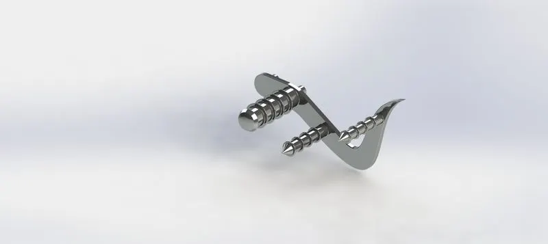
The following Features which i used to creat this part are
- Boss Extrude
- Fillet
- Revolve
- Dome
- Chamfer
- Linear Pattern
- Appearance
part 7
Chain
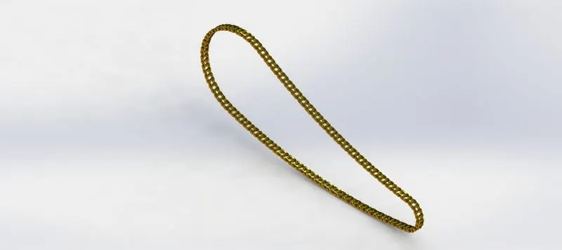
The following Features which i used to creat this part are
- Boss Extrude
- Fillet
- Curve pattern
- Fillet
- Body-Delete
- Mirror
- Appearance
part 8
Front Wheel
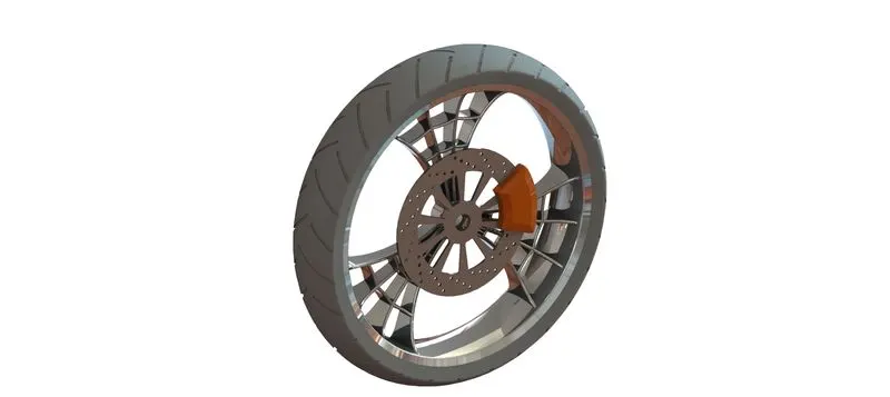
The following Features which i used to creat this part are
- Revolve one
- Bose Extrude
- Cut Extrude
- Cut Revolve
- Circular pattern
- Combine
- Fillet
- Chamfer
- Revolve
- Appearance
part 9
Rear wheel
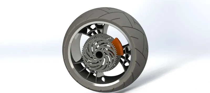
The following Features which i used to creat this part are
- Revolve
- Boss Extrude
- Cut Extrude
- Circular pattern
- Combine
- Cut Revolve
- Fillet
- Chamfer
- Appearance
part 10
Front Fork
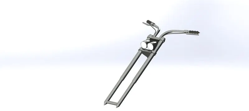
The following Features which i used to creat this part are
- Revolve
- Bose Extrude
- Fillet
- Linear Pattern
- Cut Extrude
- Dome
- Cut Revolve
- Curve Projection
- Sweep
- Mirror
- Combine
- Appearance
part 11
Chassis
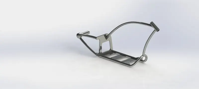
The following Features which i used to creat this part are
- Sketch Picture
- Project curve
- Sweep
- Mirror
- Boss Extrude
- Cut Extrude
- Chamfer
- Fillet
- plane
- Dome
- Split
- Combine
- Revolve
- Mirror
- Appearance
part 12
Engine
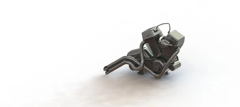
The following Features which i used to creat this part are
- Sketch Picture
- Boss Extrude
- Fillet
- Revolve
- Plane
- Circular pattern
- Dome
- Cut Extrude
- Chamfer
- Fillet
- Linear Pattern
- Mirror
- Split
- Sweep
- Combine
- Projection Curve
- Appearance
part 13
Gas tank
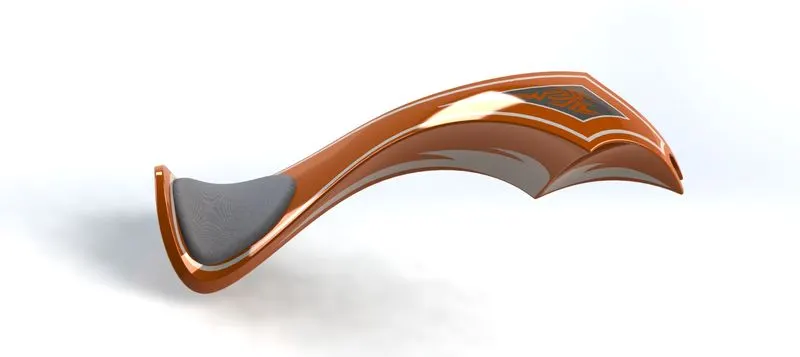
The following Features which i used to creat this part are
- Sketch Picture
- Sweep
- Surface Trim
- Project Curve
- Surface Loft
- Boundry Surface
- Mirror
- Surface Knit
- Split line
- Surface Extrude
- Fillet
- Cut Sweep
- Shell
- Appearance
Chopper Assembly
2. The following features Mates (Relations)used to creating assembly of American Chopper Are Given bilow...
- Coincident
- Concentric
- Limit aNGLE
- Width
- Distance
- Angle
- Parallel
- Tangent
Assembly model of the chopper With Different View
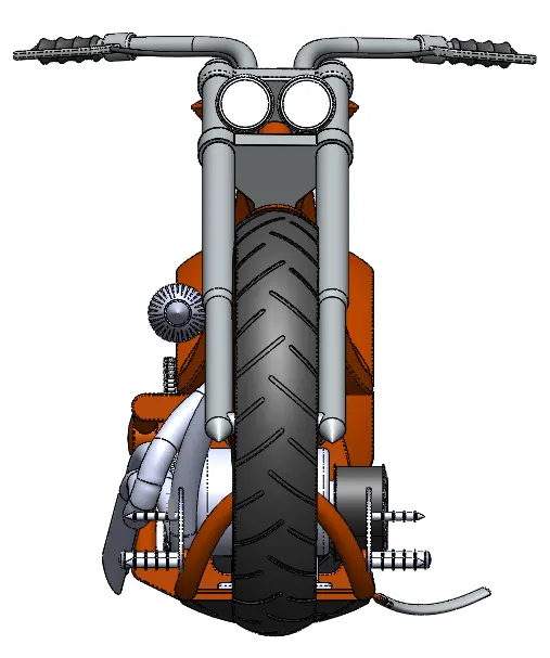
- Front View
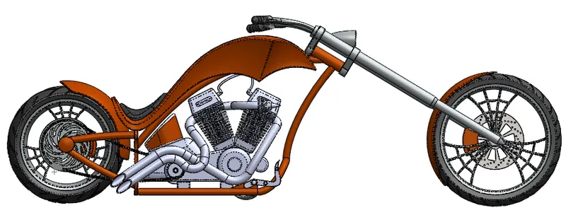
- Rightside View
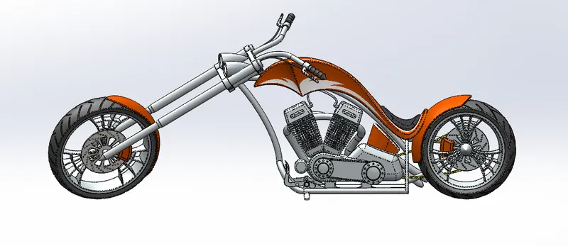
- Leftside View
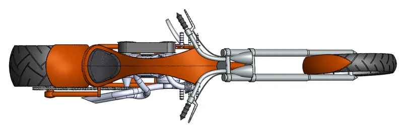
- Top View
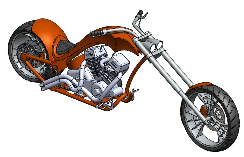
- Isometric View
Decals
Decal is a 2d image (Stickers) applied to a model. this images can be Applied to the fesses of the bodies.We have different projection methods available.
Cameras
We have Default views in solid work like top view, side view. Right view, Left view, Bottom view, etc But in case if we need Customize View then we can add Cameras at different points in space and can be adjusted to get a good view of the model.We can control the depth, focus etc of the camera
Scenes
There are different backgrounds in the Appearance that are available in solid works.
Lighting
Lighting can be added and adjusted to get shadows & realistic lighting environment so that the photo view 360 and Solid works Visualize Image Resolution gets Good Appearance We can add different lights such Ambient lights, point lights, directional lights, Spot lights etc.We can change the colour and illumination characteristics of the lights we given.
Rendering Images of Chopper Assembly
- Rendering With Photo View 360
- Camera View -1
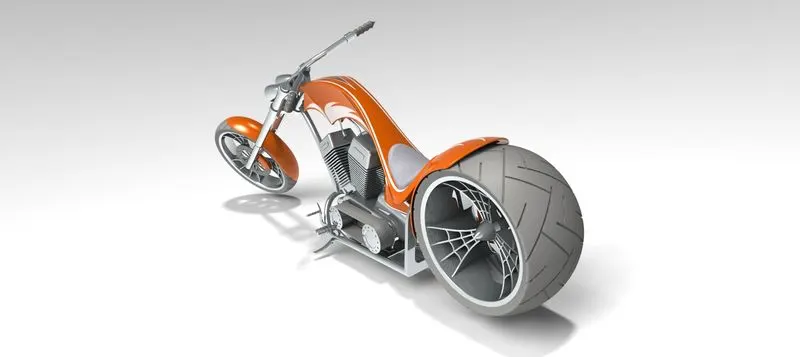
- Camera View -2
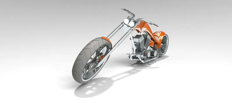
- Camera View -3
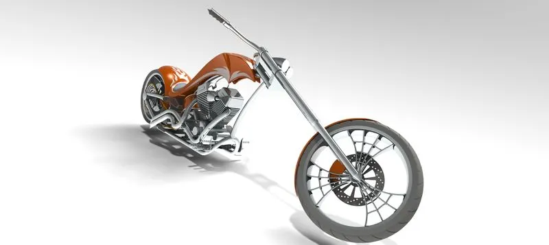
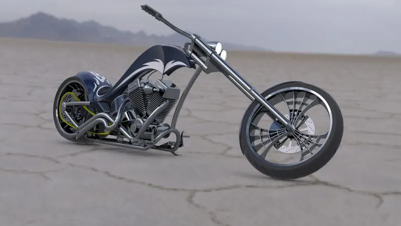
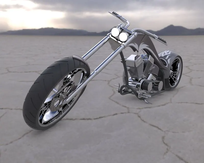
Rendering Images of Chopper Assembly
- Rendering With SOLIDWORKS Visualizetion
Conclusion:
The course teaches the basics of the solid works workbench such as Sketch constraints, in Sketching Environment, Part modeling tools, Surface modeling, Assembly of different components, Rendering using Photo view 360 and Solid works Visualize.