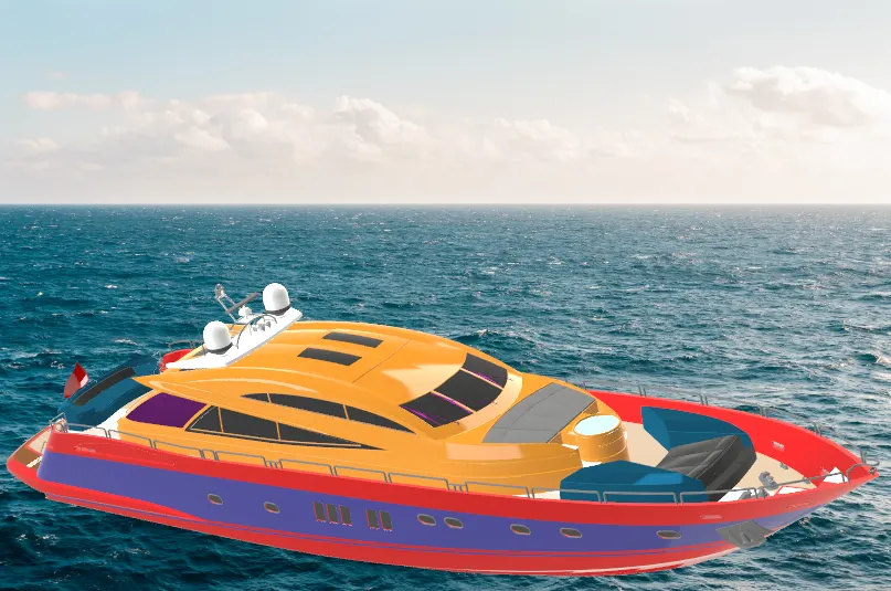
Radar Mast & Final Assembly of Yacht
Yacht:
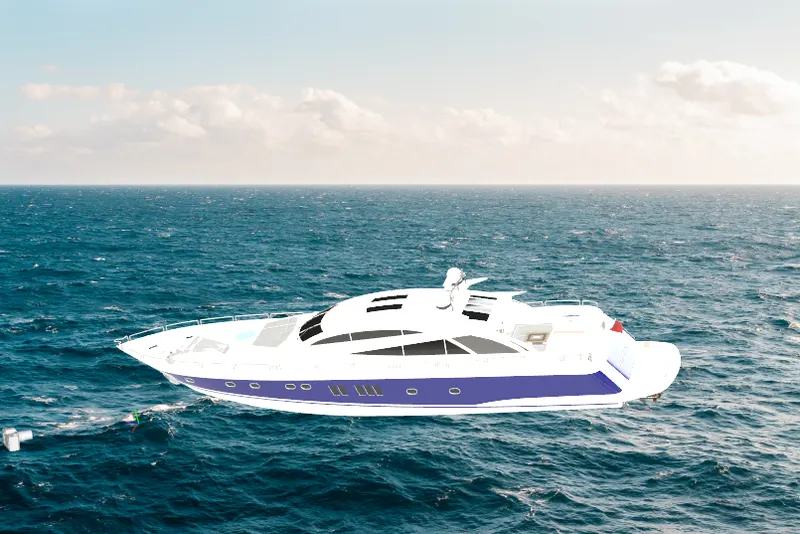
A yacht is a type of boat which is mainly used for recreation.It usually has a cabin, so it does not need to return to the harbour overnight. Originally, yachts were sailing boats, but now there are also motor yachts. The name comes from the dutch word jachtschip, which originally meant hunting-boat or fast boat. Yachts have a fixed keel.
A large motor yacht in lorient, britany, France
A yacht can vary in size from about 20 feet (6 meters) to 200 feet (60 meters) or more.
Most privately owned yachts fall in the range of about 7 meters (23 ft)-14 meters (46 ft); the cost of building and keeping a yacht rises quickly as length increases. In the United States, sailors tend to refer to smaller yachts as sailboats, while referring to the general sport of sailing as yachting. In sailboat racing, a yacht is any sailing vessel taking part in a race.
DESIGN METHODOLOGY :
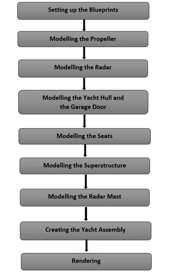
Different parts in yacht:
Propeller
Radar
Hull
Garage door
Front seat
Middle seat
Rear seat
Superstructure
Radar mast
- Setting up the Blueprints :
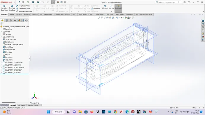
All the blueprints were imported into a Solid-works part file using the path : Tools - Sketch Tools - Sketch Picture.
Appropriate positioning as well as scaling of the blueprints is very important and has to be done perfectly as shown.
This Blueprint setup is then used to model all the parts.
- Modeling of Propeller:
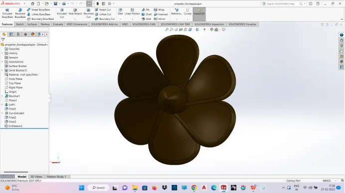
A propeller is a rotating fan-like structure which is used to propel the ship by using the power generated and transmitted by the main engine of the ship.
A propeller is a device with a rotating hub and radiating blades that are set at a pitch to form a helical spiral, that, when rotated, performs an action which is similar to archimidies screw. It transforms rotational power into linear thrust by acting upon a working fluid, such as water or air.The rotational motion of the blades is converted into thrust by creating a pressure difference between the two surfaces. A given mass of working fluid is accelerated in one direction and the craft moves in the opposite direction. Propeller dynamics, like those of aircraft wings, can be modeled by Bernoulli's and newton's third law.Most marine propellers are screw propellers with helical blades rotating on a propeller shaft with an approximately horizontal axis.
Some import tools used to model the propeller is line, circle, corner rectangle, revolve, surface loft, boss base extrude, cut extrude, fillets, circular patterns etc.,
- Modelling the Radar :
Marine Radars are X band or S band radars on ships, used to detect other ships and land obstacles, to provide bearing and distance for collision avoidance and navigation at sea.
They are electronic navigation instruments that use a rotating antenna to sweep a narrow beam of microwaves around the water surface surrounding the ship to the horizon, detecting targets by microwaves reflected from them, generating a picture of the ship's surroundings on a display screen.
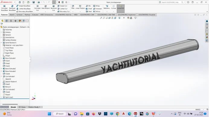
The Radar is modeled very easily using the following features - Extruded Boss/Base, Cut Exrtude, Fillets, etc.
Since, the radar is symmetric in shape, only half the portion is modeled.
The other half is simply mirrored using the Mirror feature. The Merge Solids option is enabled while doing so.
A text is added on the surface just for the sake of a better and realistic outlook.
The text feature can be found at the mentioned path :
Tools - Sketch Entities - Text.
This text is then projected on the radar surface using the Split Line command.
- Modelling the Hulland garage door:
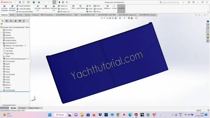
A Hull is the watertight body of a ship or boat. The hull may open at the top (such as a dinghy), or it may be fully or partially covered with a deck.
Atop the deck may be a deckhouse and other superstructures, such as a funnel, derrick, or mast. The line where the hull meets the water surface is called the waterline.
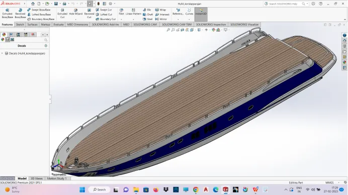
Here, the hull is essentially modeled by Surface Modelling.
The outer surfaces of the Hull are created using the features in the Surfaces tab.
For this, the Project Curve feature along with the different sketch tools, is used to create the outer peripheries of the surfaces.
Then, the surfaces are created using these curves and by using features such as Lofted Surface, Boundary Surface, Extruded Surface, Trim Surface, etc.
The Port Holes are modeled by using the Swept Boss/Base features after using Extruded Cut.
The railing is modeled by creating projected curves through different sketch tools and then by using the Swept Boss/Base command with the curves as the sweep path.
Fillet is used at all the required places where sharp edges are to be avoided. Also, providing fillets around the windows gives a good aesthetic appeal to the model.
The Anchor is modeled directly as a solid i.e by using the features such as - Extruded Boss/Base, Extruded Cut, etc.
These two symmetric parts are then carefully knitted together using the feature Knit Surface.
The Create Solid option is enabled to fill the inside portion of the Hull.
While doing so, it is ensured that the knitting is done properly. This can be done by carefully looking at each and every edge. A perfectly knitted edge looks black in colour, while a blue edge means that there is no association between the two faces altogether.
To give a more realistic outlook, decals are added on the deck surface as well as the stair surfaces.
Since, the Hull is symmetric, only half the portion is modeled, the rest half is mirrored using the Mirror feature.
Appearances is changed by providing colour at all the required faces. This gives the model a perfect and realistic look.
- Modelling the Seats :
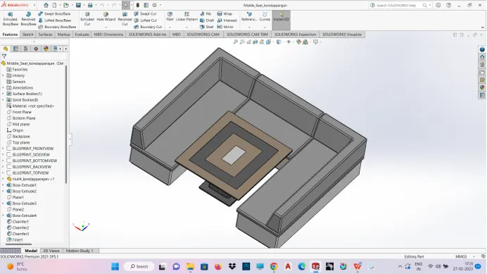
Seats are modeled either by solid features or by using surface features.
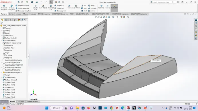
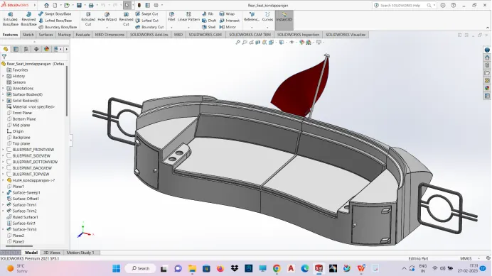
There are three seating in the model - Front, Middle and Rear.
Here, the Front and the Rear seats are modeled by first creating the outer surfaces using the features of the Surface tab. Then by creating a solid after carefully knitting the surfaces together using the Knit Surface feature.
- Modeling of Superstructure
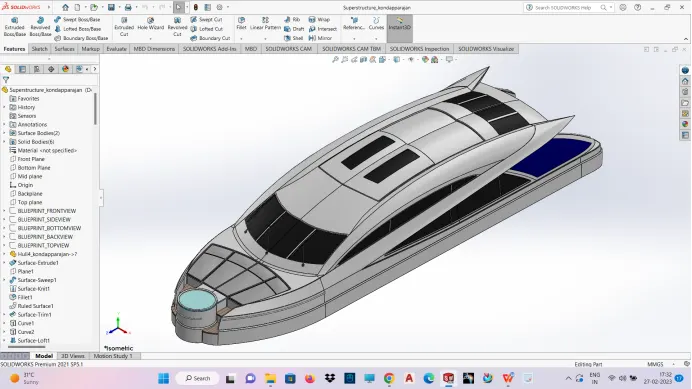
The superstructure covers everything above the substructure, from walls to floors to roofing. The purpose of the superstructure is to enclose and divide space, as well as spread loads safely into the substructure.
A superstructure is an extended construction of any building or platform that rises above the rest of the building or platform in a distinct manner. The word comes from a combination of two Latin words, the Latin prefix ‘super’ means in addition or above or in excess of, whereas the stem word ‘structure’ means to build or to heap up. Thus, superstructure means to add a construction to an already existing structure. In ships this is the name given to the part of the ship that emerges from the deck. However any mast, sails, any armaments or arsenal are not included in this category.
The size of the superstructure has a great influence on the mobility of the vessels. They are designed in a manner, so that, they add value and hinder the speed and mobility in the least. The superstructure is mostly designed in fashion as well. This is because it is the most easily visible part of the ship, in fact it is the identification of the ship, and so the designers try to provide it with the identity that is unique.
Some important tools used to build the superstructure is line, circle, corner rectangle, surface extrude, surface sweep, surface knit, surface loft, surface trim, projected curve, ruled surface, surface extend, sweep, boss extrude, cut extrude, chamfer etc.,
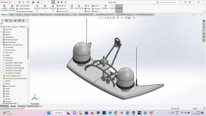
- Modelling the Radar Mast :
The Mast of a sailing vessel is a tall spar, or arrangement of spars, erected more or less vertically on the centre-line of a ship or boat.
Its purposes include carrying sails, spars, and derricks, and giving necessary height to a navigation light, look-out position, signal yard, control position, radio aerial or signal lamp.
Large ships have several masts, with the size and configuration depending on the style of ship.
Here, the mast consists of 2 light bulbs on 2 antennas.
This mast is easily modeled using the solid features such as Extruded Boss/Base, Revolved Boss/Base, Swept Boss/Base, etc.
The horns are modeled by using the Shell feature. This feature essentially removes off the inside material out of a solid 3D part, thereby making it hollow.
The Mirror feature is used to mirror symmetric entities.
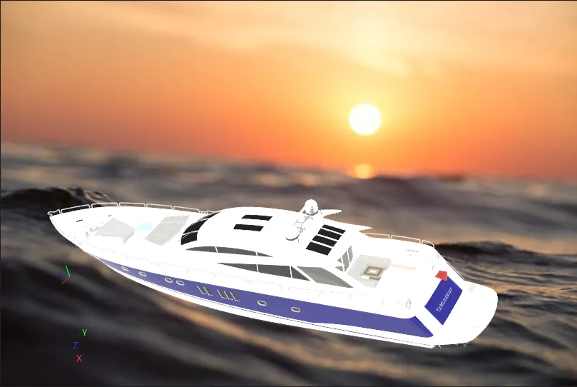
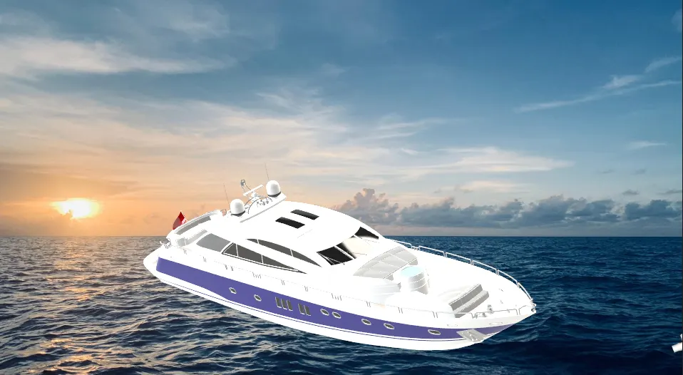
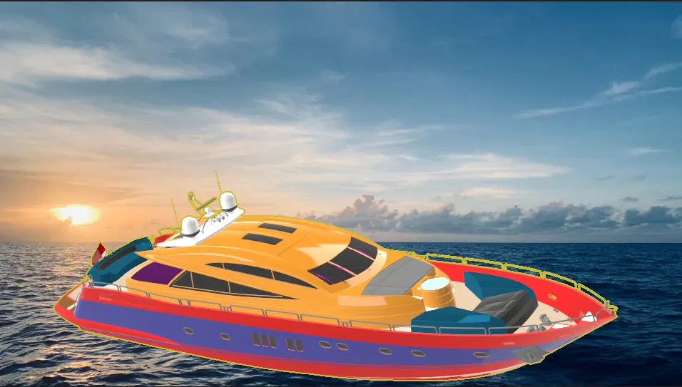
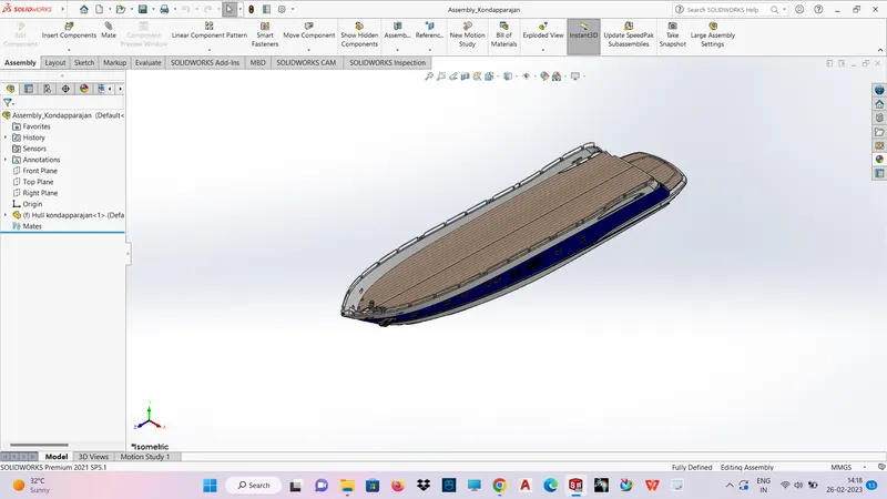
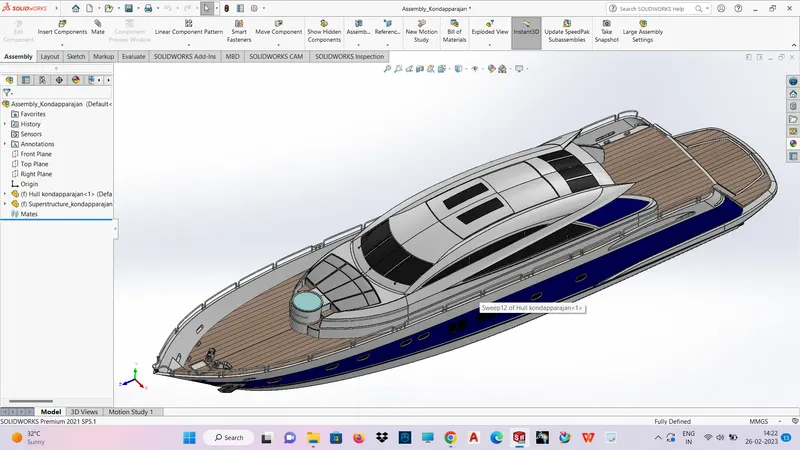
Assebbling the components of yacht:
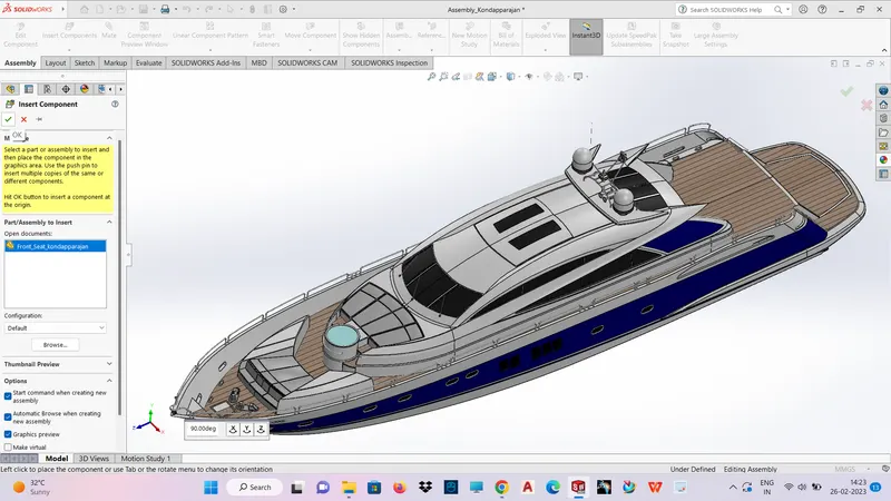
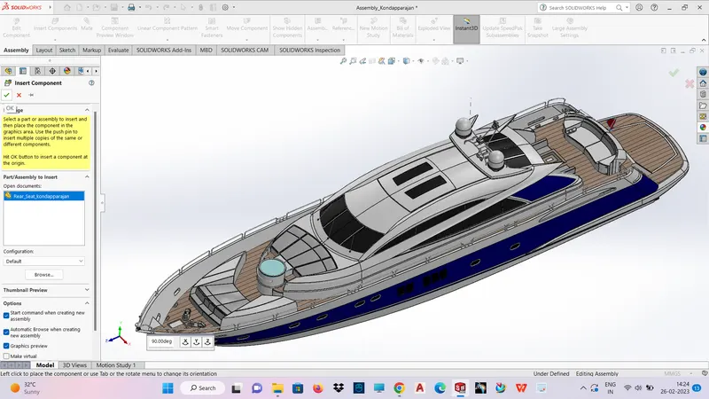
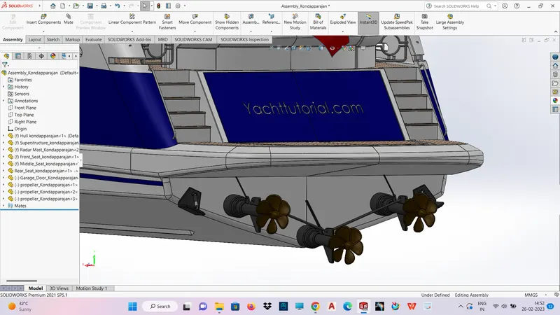
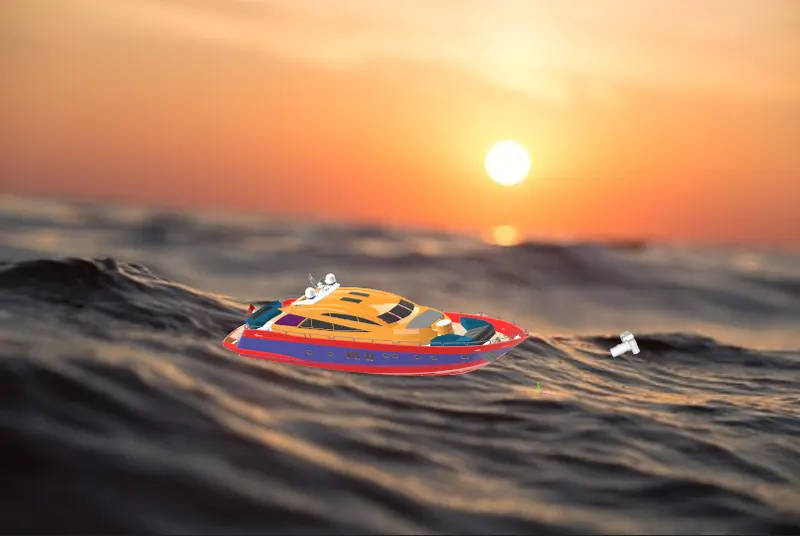
Rendering the yacht using solid works visualize: