Radar Mast & Final Assembly of Yacht
OBJECTIVE:- The main goal of this modelling is to create a detailed model of the various components of a SUNSEEKER PREDATOR YACHT and to apply Decals and paint to the model. After doing assembly of different components, the final assembly model must be rendered with the appropriate environment and appearances.
INTRODUCTION:- In this project, Solidworks is used to design the Sunseeker predator yacht. Here, we take 2D sketches and create 3D models out of them. We accomplish this using tools and features for surface modelling and solid modelling. We put the parts together after they are designed by adding the appropriate mates and constraints. After that, we can comprehend how to render a yacht in a photorealistic manner using Solidworks visualise and photo view 360.
DESIGN METHODOLOGY:- The flowchart of design methodology is given beow:-
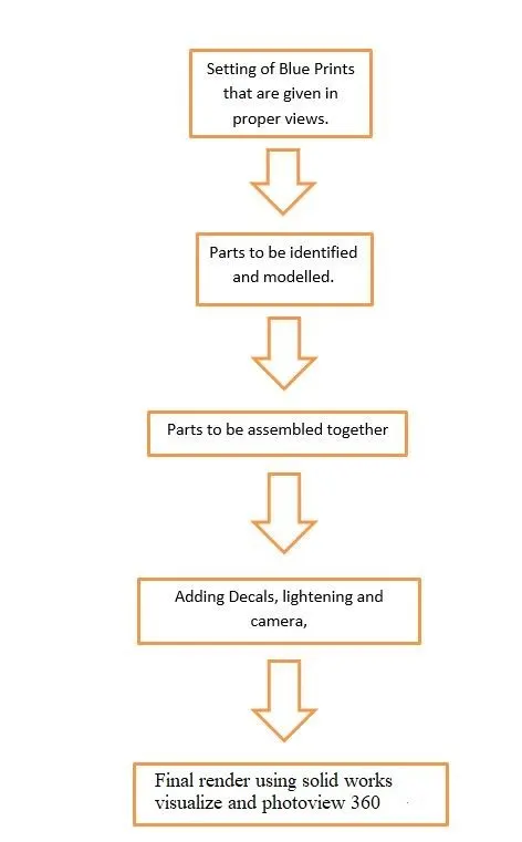
Fig 1: Design Methodology
Parts to be Modelled:-
- Propeller
- Hull
- Radar
- Garage Door
- Front Seat
- Middle Seat
- Rear Seat
- Radar Mast
- Superstructure
Tools and Features Used:-
TOOLS AND FEATURES USED:- The tools and features used are as follows.
1. Line: Using this capability, we can draw a straight line. Sketching can be done using a solid line or a construction line.
2. Circle: Using this capability, we can draw circles.
3. Rectangle: Using this feature, you may draw squares or rectangles.
4. Spline: We can make curved lines using this capability.
5. Arc: We can draw arcs using this capability.
6. Extend: Using this ability, we can make the sketches longer.
7. Trim: You can trim sketches using this feature.
8. Split: This feature splits bodies using a drawing.
9. Projected curve: In this feature, a curve is created by combining two sketches and projected over or on the part which you want.
10. Extrude body: With the help of this ability, we may create solid bodies from 2D sketches.
11. Extrude cut: Using this ability, we can make holes or cuts in the solid bodies of any shapes.
12. Swept Bose: Using this feature, we can build a solid body by guiding that body along a curve or a path curved body.
13. Mirror: With this capability, we may create a carbon copy of the solid body by selecting a reference plane or face.
14. Revolve: This enables us to create a solid body that revolves around an axis. That axis can also be called as axis of revolution.
15. Linear patterns: let us make patterns that are arranged in a straight line.
16. Circular Pattern:The ability to build a circular pattern of a particular profile is provided by this.
17. Shell: This is used to hollow out a solid body.
18. Split Entities: This divides a line into two or more halves.
19. Mirror Entities: This is how a sketch mirror is made.
20. Dome: This feature is utilised to produce a dome-shaped solid by covering a flat solid body with it.
21. Loft: This function enables us to design solid bodies with irregular geometry. By using this feature we can make solid body with the help of two sketches that are separate from each other.
22. Plane: This capability is used to generate a new plane using one or more references.
23. Chamfer: This characteristic is utilised to produce slanted edges.
24: Fillet: This is used to make sharp edges into circular margins.
17. Shell: This is used to hollow out a solid body.
18. Split Entities: This divides a line into two or more halves.
19. Mirror Entities: This is how a sketch mirror is made.
20. Dome: This feature is utilised to produce a dome-shaped solid by covering a flat solid body with it.
21. Loft: This function enables us to design solid bodies with irregular geometry.
22. Plane: This capability is used to generate a new plane using one or more references.
23. Chamfer: This characteristic is utilised to produce slanted edges.
24. Fillet : This is used to create edges that are circular.
SURFACE FEATURES:- The surface features are as follows.
1. Extruded surfaces: This command is used to creates a surface that extends from the shape of a curve.
2. Lofted surface: Loft Surfaces are created when more than one 3D Curve is used to create a smooth tangency between the chosen curves.
3. Trim surface: A trimmed surface consists of two components: a surface that underlies everything and establishes the geometric shape, and trimming curves that identify the trimmed-away portions of the underlying surface. 4. Surface sweep: This technique is used to construct a surface along a curve or a line.
5. Boundary surface: You can generate surfaces with the boundary surface feature that can be tangent or continuous in both directions (all sides of the surface). This typically produces results of higher quality than the loft tool.
6. Ruled surface: This allows surfaces to be built up from their edges.
7. Extend surface: This is used to increase the size of the current surface by selecting the edge of the surface.
8. Offset surface: This is used to offset any surface.
Expalining the models created for yachact assembly
1. Propeller:- An object with blades attached to a boat or aircraft is called a propeller. The propeller is rotated by the engine that helps the boat or aircraft to move.
Tools and Features used in Propeller
- Sketch
- Line
- circle
- Loft
- Rectangle
- Revolve
- Circular Pattern
- Fillet
- Extrude Cut
Images of different views given below:-
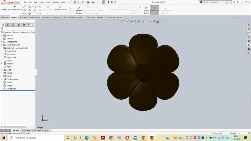
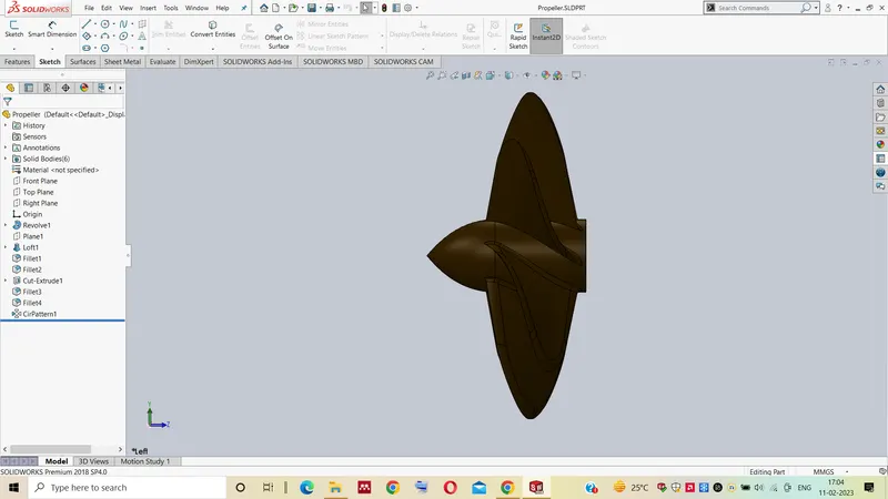
Front View Side View
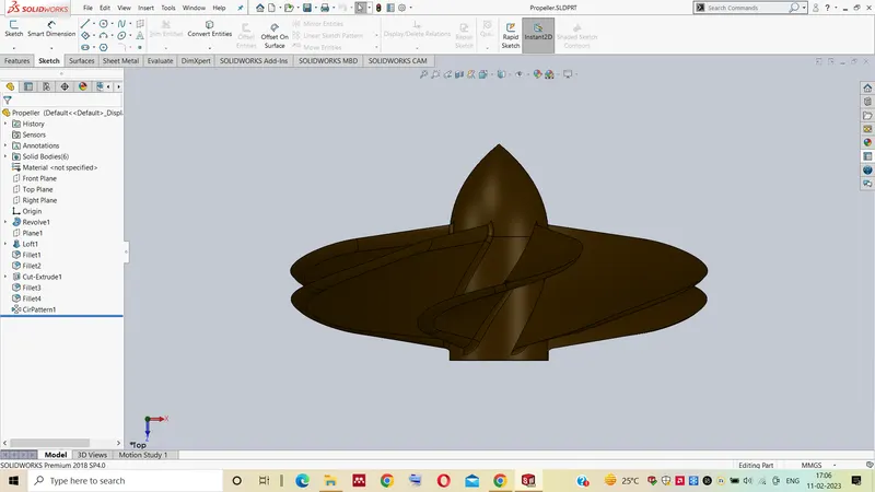
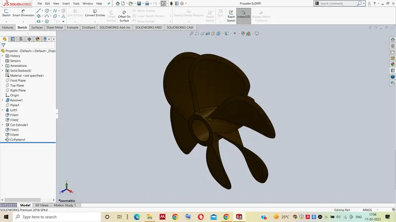
Top View Isometric View
2. Radar:- (RAdio Detecting And Ranging) Boaters' primary navigational assistance is a marine radar system. Even in low visibility, it helps in the detection of boats, birds, landmasses, and weather systems.
Tools and Features used in Radar
- Sketch
- Extrude
- Fillet
- Line
- Polygon
- Circle
- Text Mirror
Images of different views given below:-
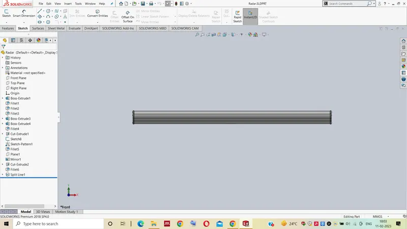
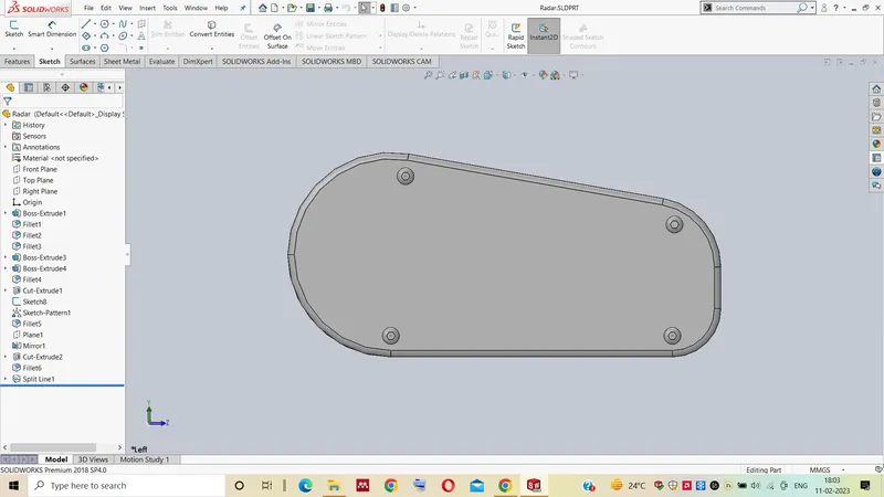
Front View Side View
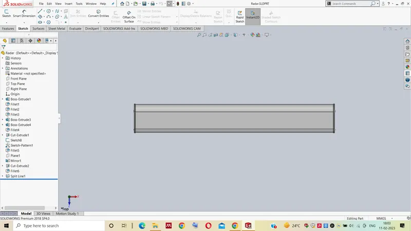
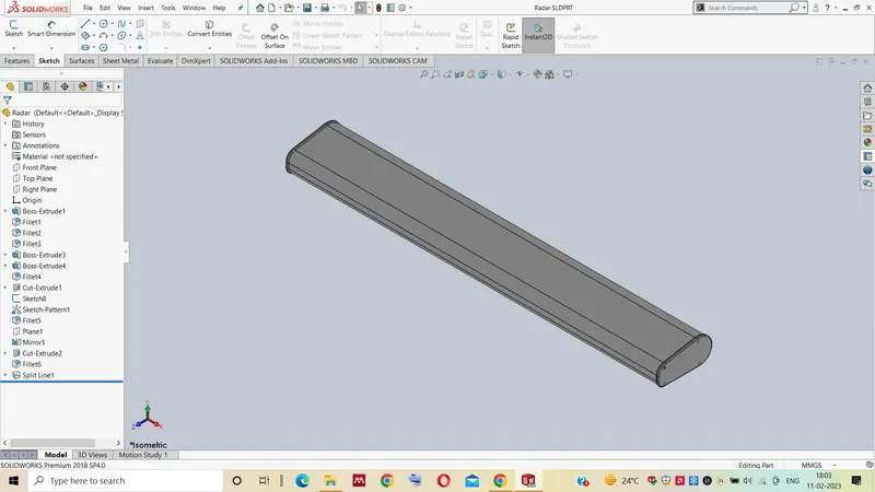
Top View Isometric View
3. Garage Door:- It is the door of the storage that is present in the backside of the yachat.
Tools and Features used in Garage Door
- Extrude Cut
- Mirror
- Text
- Fillet
- Shell
Images of different views given below:-
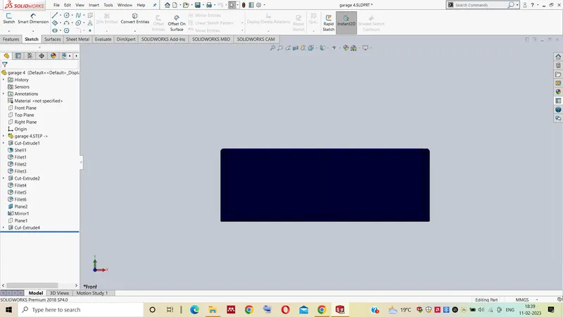
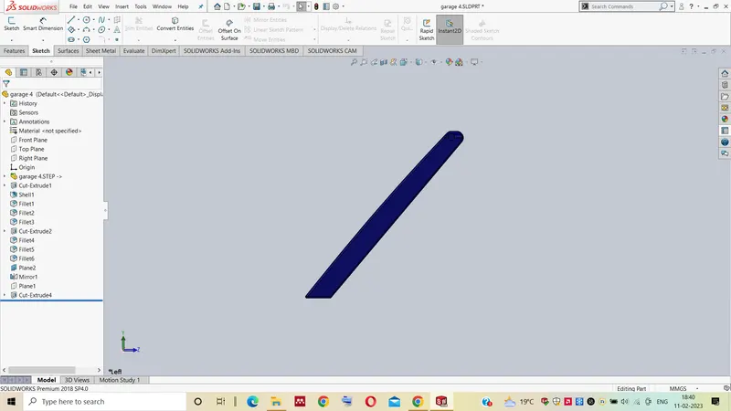
Front View Side View
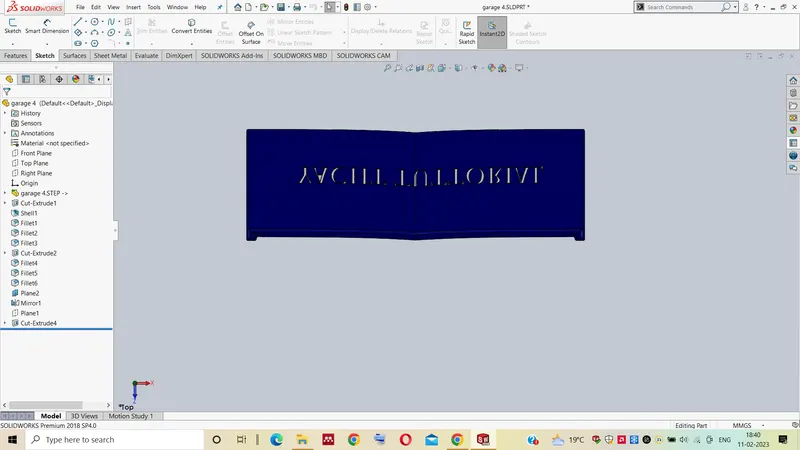
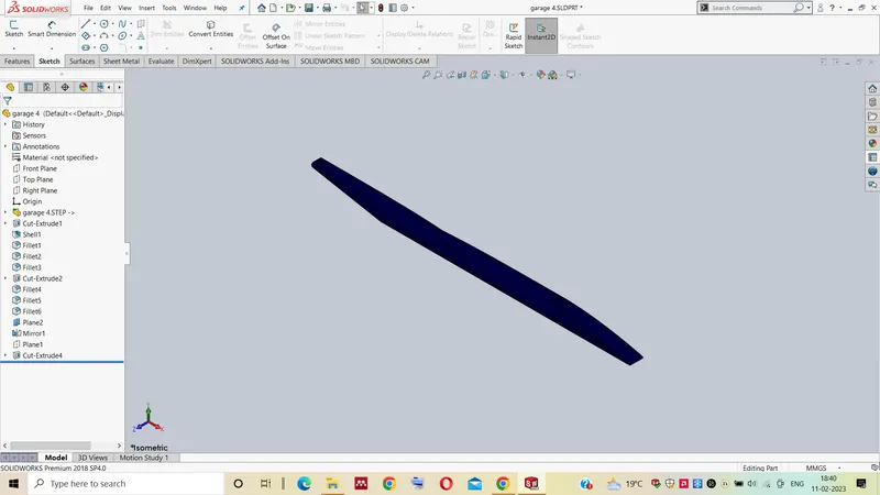
Top View Isometric View
4. Hull:- The frame or body of a ship or boat exclusive of masts, yards, sails, and rigging. the main body of a usually large or heavy craft or vehicle (such as an airship or tank).
Tools and Features used in Hull
- sketch
- Line
- Circle
- Projected curve
- Linear pattern
- Mirror
- Extrude surface
- Surface loft
- Extrude Cut
- Fillet
- Chamfer
- Sweep Surface
- Knit Surface
- Trim Surface
- Offset
- Shell
- Helix
- Plane
Images of different views given below:-
Front View Side View
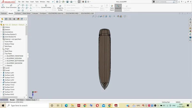
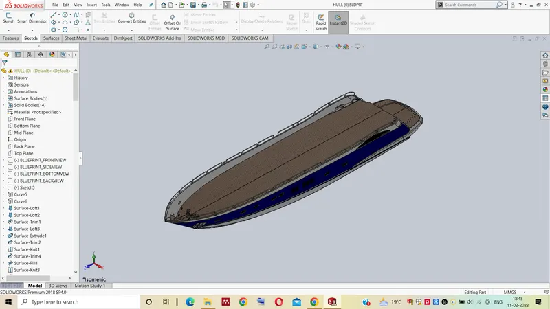
Top View Isometric View
5. Superstructure:- The superstructure of a ship or boat refers to the sections that is above the main deck, including sailboats, fishing boats, passenger ships, and submarines. Typically, this excludes any turrets or masts it may have.
Tools and Features used in superstructure
- Line
- Spline
- Circle
- Extrude cut
- Projected curves
- Offset
- Surface Fill
- Surface Extrude
- Surface Sweep
- Dome
- Surface Trim
- Extend Surface
- Surface Knit
- Plane
- Ruled Surface
- Split Entities
- Split Lines
- Delete Faces
- Fillet
- Chamfer
- Mirror
Images of different views given below:-
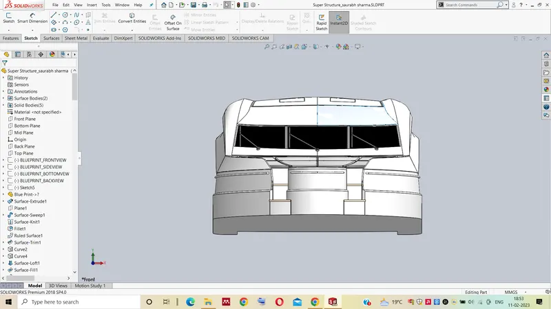
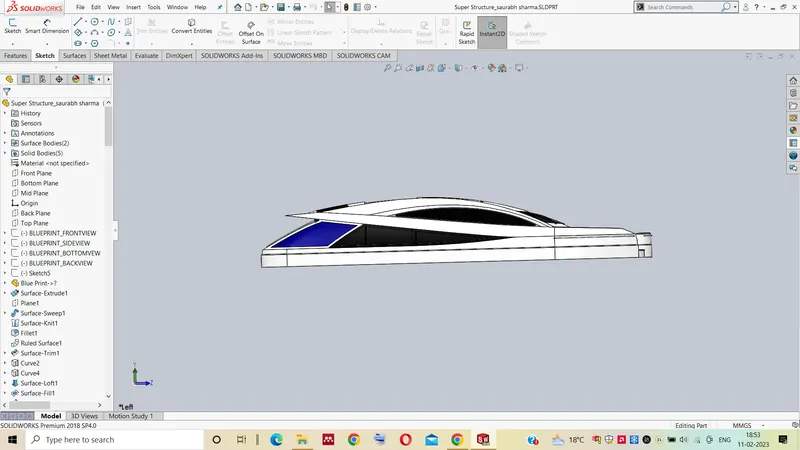
Front View Side View
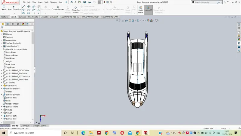
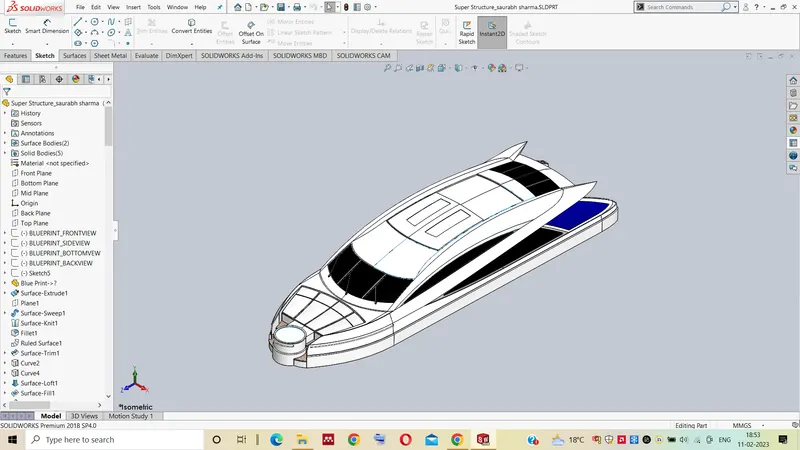
Top View Isometric View
6. Front Seat:- It is placed at the front of the yacht for the convenience of the passengers.
Tools and Features used in Front seat
- Sweep Surface
- Loft Surface
- Trim
- Extrude Cut
- Revolve
- Surface Knit
- Surface Fill
- Dome
- Mirror
- Fillet
- Chamfer
Images of different views given below:-
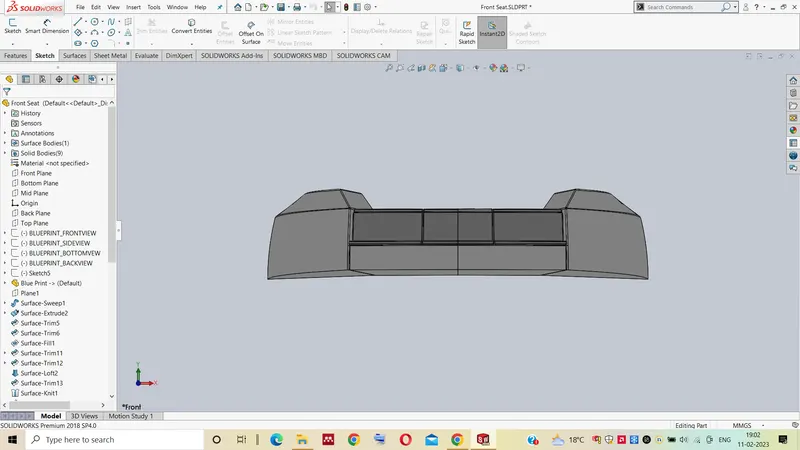
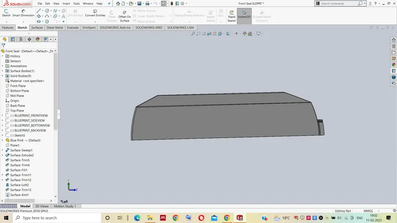
Front View Side View
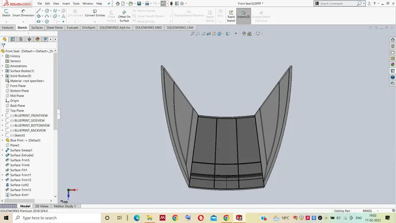
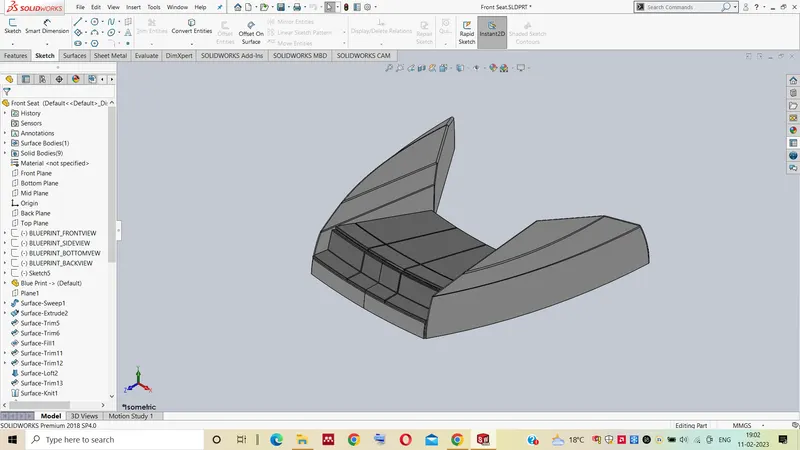
Top View Isometric View
7. Middle Seat:- For the elegance and comfort of the passengers, it is in the middle of the boat.
Tools and Features used in Middle seat
- Extrude Bose
- Chamfer
- Fillet
- Mirror
- Line
- Rectangle
Images of different views given below:-
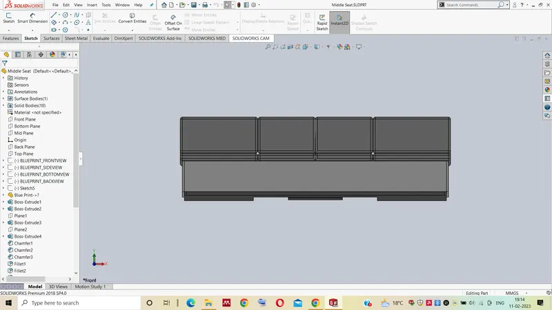
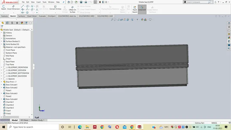
Front View Side View
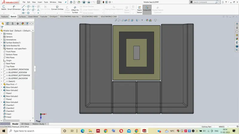
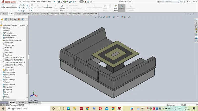
Top View Isometric View
8. Rear Seat:- It is situated on the back side of the yacht for the convenience of the passengers.
Tools and Features used in Rear seat
- Surface loft
- Surface extrude
- Surface Offset
- Surface trim
- Sweep
- Ruled Surface
- Surface Extend
- Surface Knit
- Surface Extend
- Extrude Bose
- Chamfer
- Extrude Cut
- Mirror
- Plane
- Fillet
Images of different views given below:-
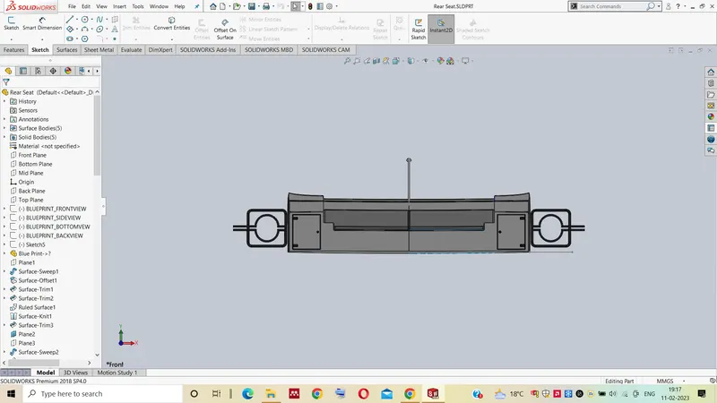
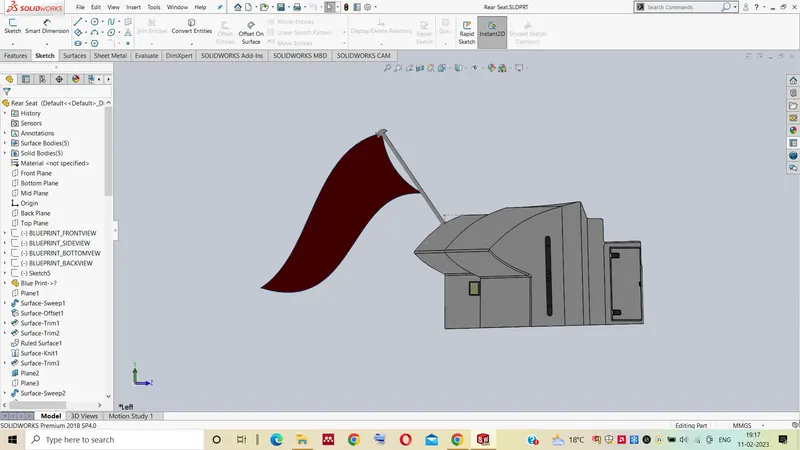
Front View Side View
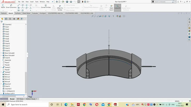
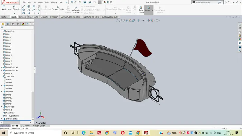
Top View Isometric View
9. Radar Mast:- A frame that holds the radar is known as a radar mast. Above the superstructure surface, it is situated.
Tools and Features used in Radar Mast
- Spline
- Extrude Bose
- Revolve
- Circle
- Mirror
- Line
- Fillet
- Chamfer
- Shell
- Projected curve
Images of different views given below:-
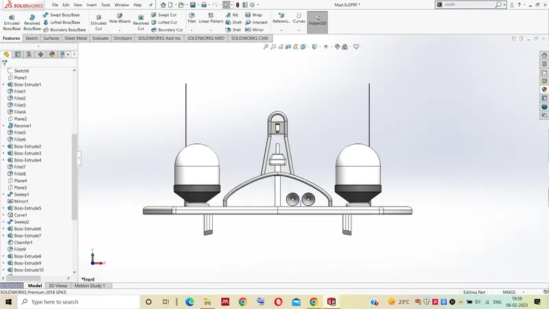
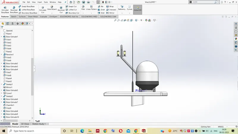
Front View Side View
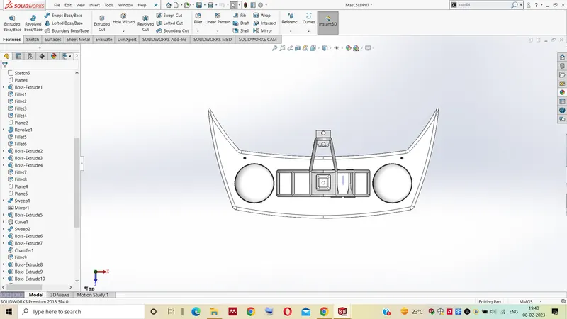
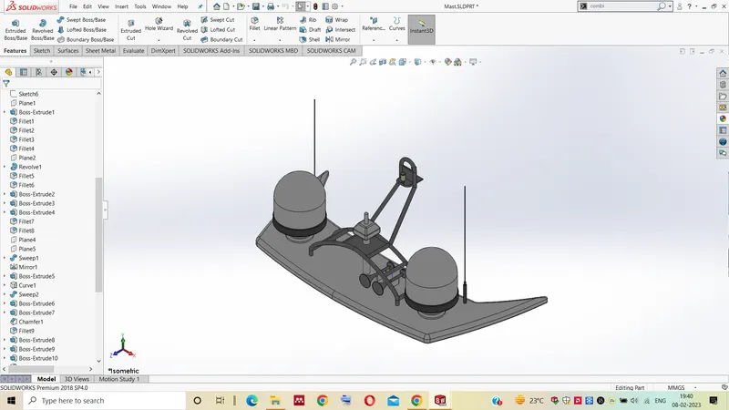
Top View Isometric View
Feature Tree
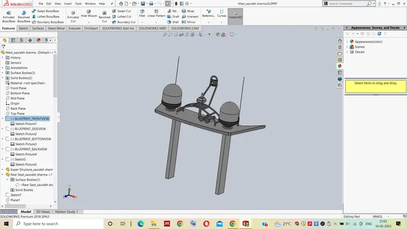
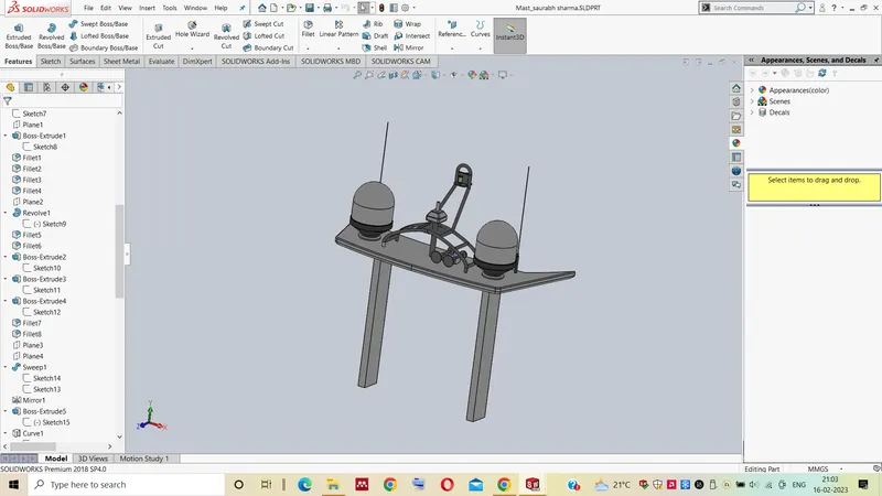
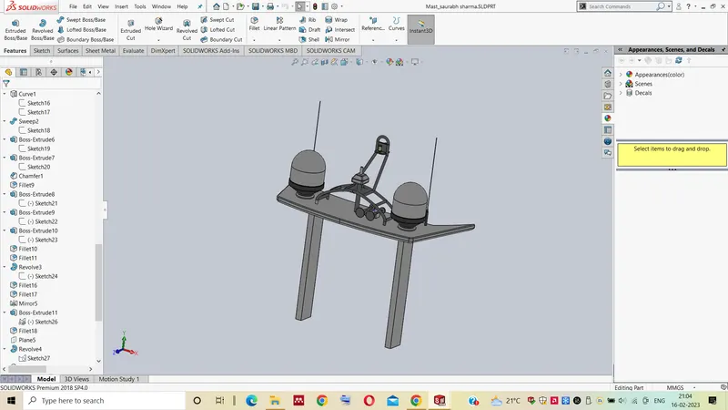
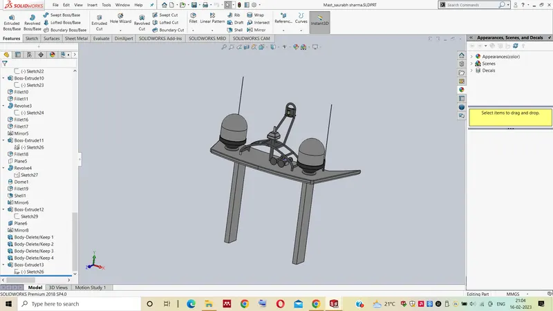
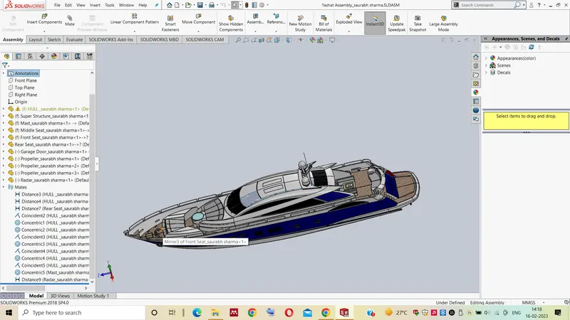
10. ASSEMBLY OF SUNSEEKER PREDATOR YACHT:- Using the insert parts option, the hull portion is initially fitted into the assembly. By selecting OK, the part is then corrected and added to the assembly environment. The remaining components of the yacht are then assembled, and the potential requirements for mate are stated.
Features used in assembly
- Mates
- Insert part
Mates:- Mates define the geometric relationships between assembly parts. As we add mates, we specify the permitted directions for the components' linear or rotational motion. We can transfer a component within their range of degrees of freedom while imagining how the assembly would behave.
Insert part:- In this the different component that is to be mated with the other components are inserted with this command and after that mates is done to complete the YACHAT ASSEMBLY.
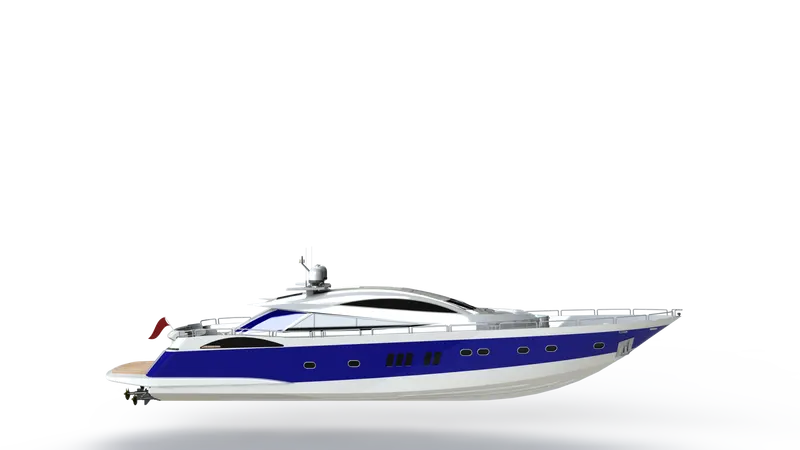
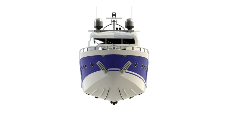
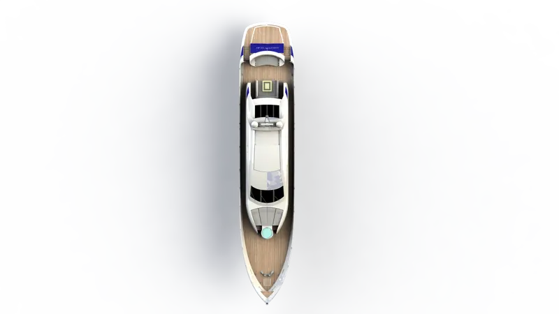
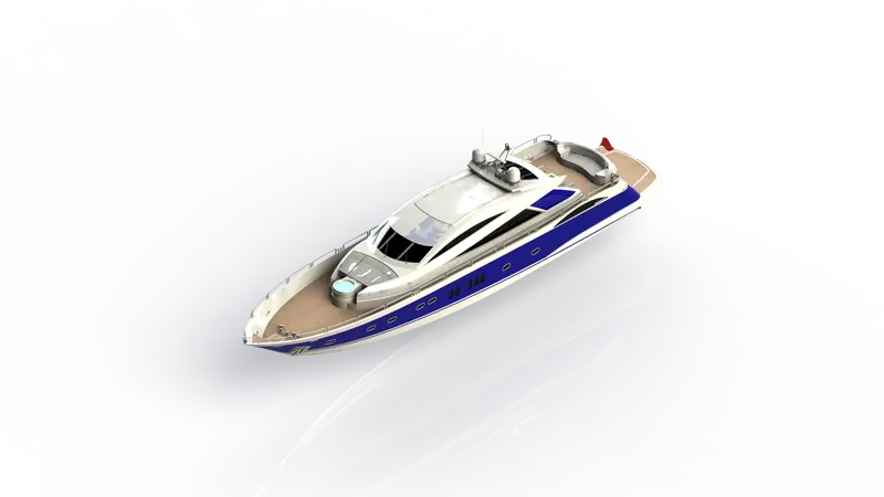
Images of different views given below:-
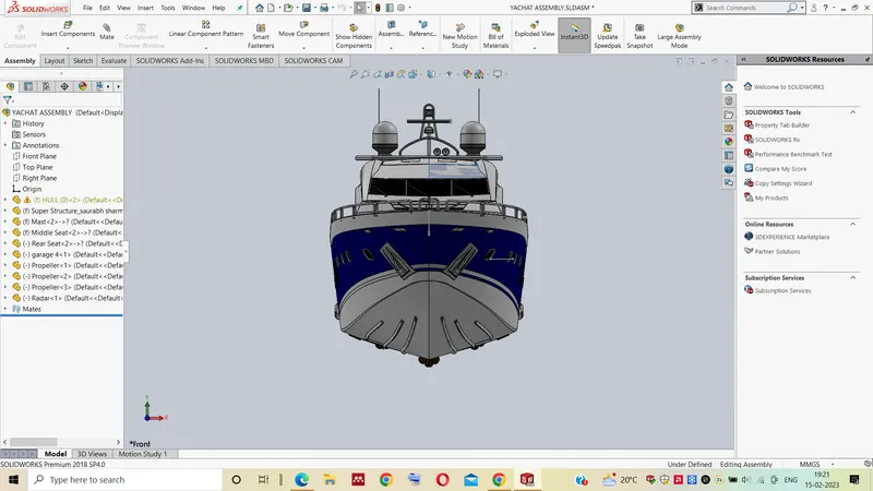
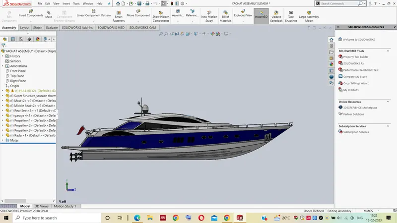
Front View Side View
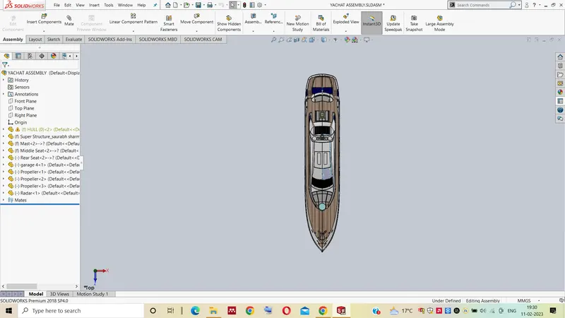
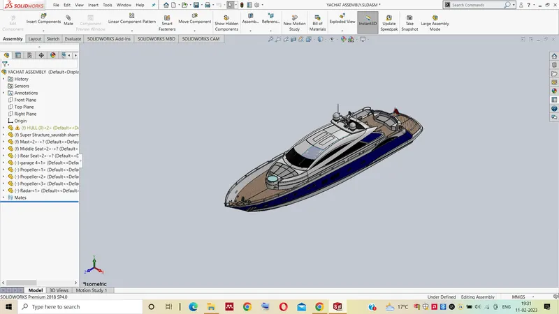
Top View Isometric View
Feature Tree:- The images of feature tree are below.
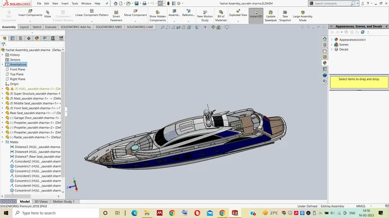
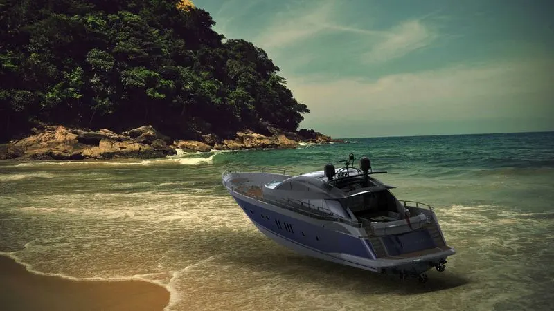
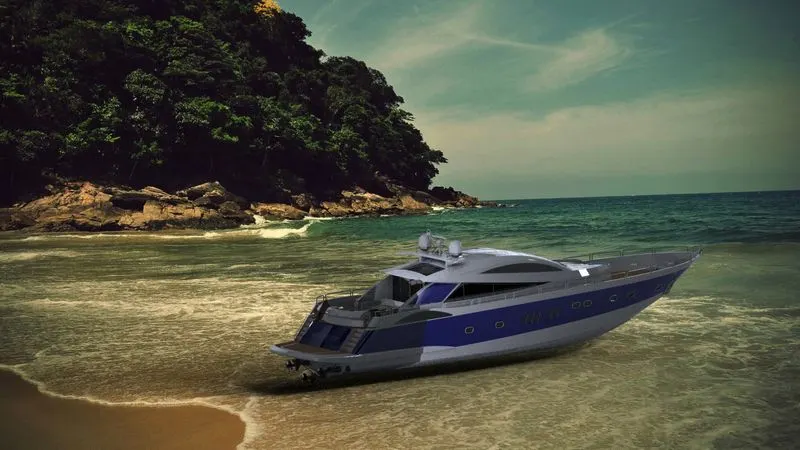
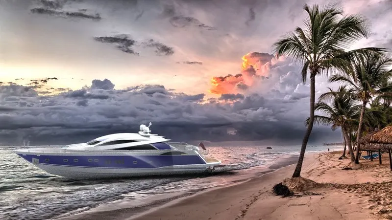
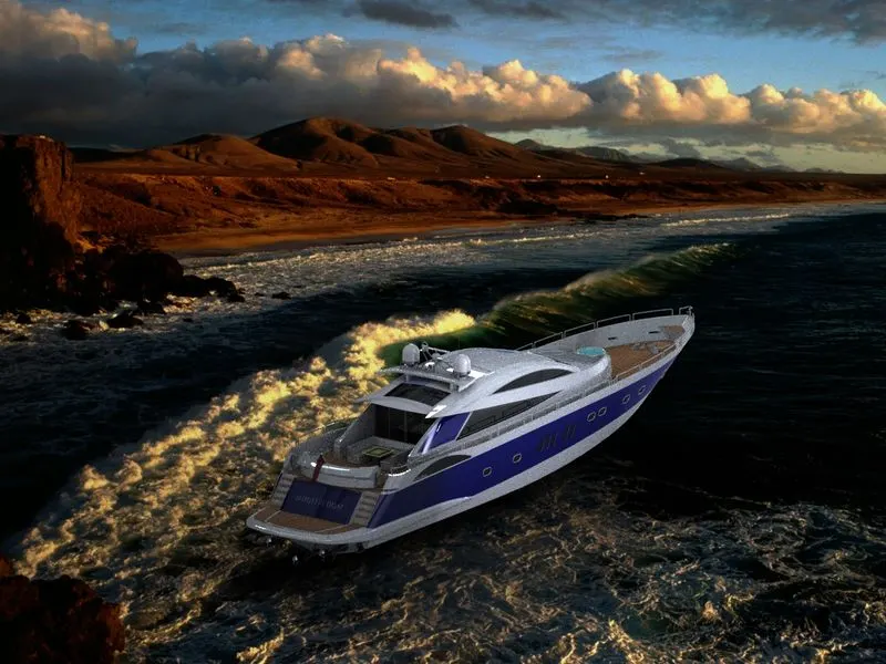
Rendering:- This enables the quick and simple generation of visual material that conveys a designer's vision and allows you to show your skills in the most beautiful way. This rendering can be done with the help of
- PhotoView 360
- Solid works Visualize
Some reder images of solidworks Visulaize is given below:-
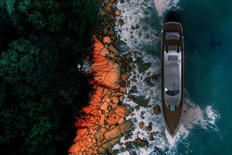
Some images of PhotoView 360 are given below:-