Photo Realistic Rendering
1. Report on assembly of American Chopper Model
Designing of American Chopper Model using Solid works
Objective
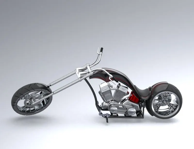
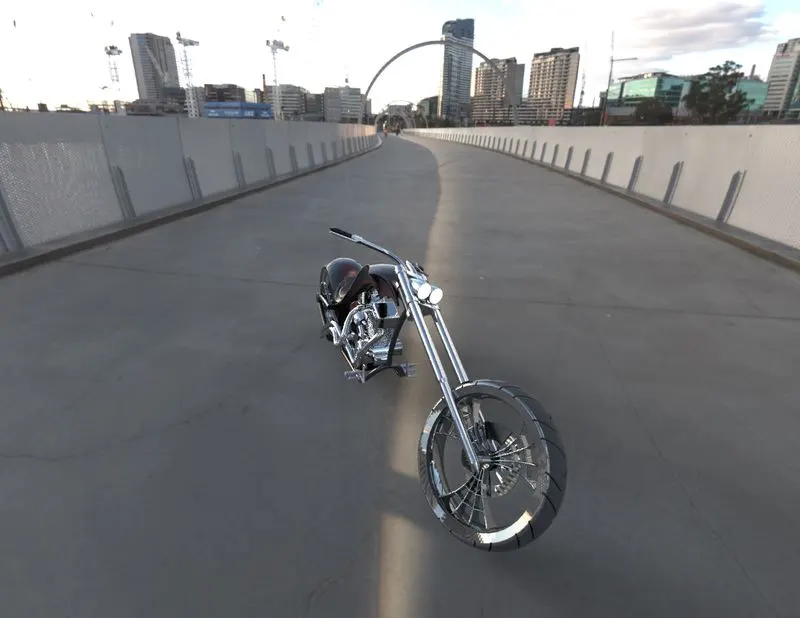
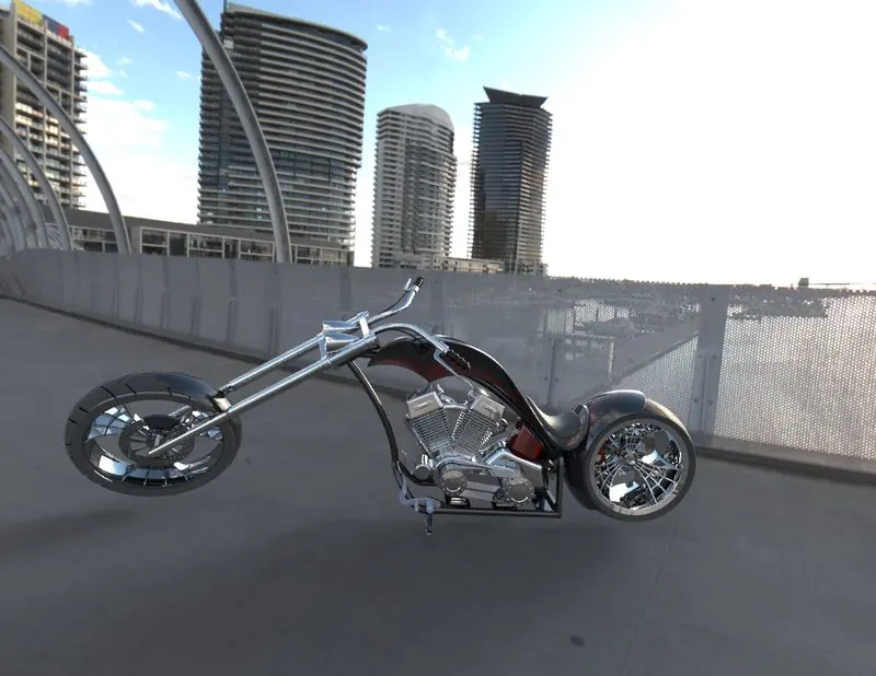
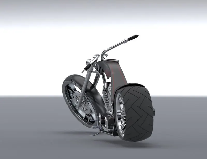
An American Chopper will be modelled using the CAD (computer aided drafting) programme SOLIDWORKS, and will then be rendered using SOLIDWORKS Visualize to produce a photorealistic representation of the vehicle.
Methodology
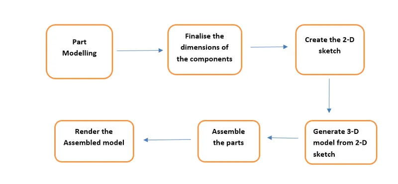
Part Modeling
In part modelling, the 2D part sketch is first created using the tools in the sketch tab, and the 2D part sketch is then transformed into a 3D part utilising features present in the features tab.
Features Used
Boss Extrude: This function expands the object in 3D in accordance with the sketch plane.
Extrude Cut: This feature is used to cut or remove a 3D object in a straight line in accordance with a drawing.
Fillet: A feature utilised to create smooth, rounded internal or external edges in order to prevent sharp edges.
Lofted boss/base : It is a feature that is used to create Complex Shapes. It accomplishes this by interpolating surfaces between different model cross-sections. Sketches, faces, or edges can be included in these cross-sections.
Split: To divide a single solid component into two solid components, use the split tool. It is used to project an object onto curved or planar surfaces.
Dome: A dome-shaped extrusion, such as an elliptical dome, can be made with this feature.
Shell: By choosing the outer wall of the solid part and subsequently removing the inside portions, the shell feature is utilised to create a hollow area in a solid part. Additionally, it is applied to lessen a particular thickness.
Combine: The combine tool is used to integrate two solid elements that cross each other and form a single solid part.
Chamfer: In place of being perfectly square, chamfering is utilised to create sharp edges and corners that are slightly tapered.
Linear Pattern: The linear parent is used to create a different number of instances required to create the pattern linearly.
Curve Driven Pattern: A curve driven pattern is one that follows a previously designed curve to create any pattern.
Circular pattern: A feature that converts 3D features into circular patterns based on the number of insistences is known as a circular pattern.
Revolve boss/base: The revolve function is utilised to create a 3D extrusion that is cylindrical or circular along with a specified reference axis according to a sketched design.
Revolve cuts: This feature is used to eliminate or lessen the extrusion of cylindrical, round surfaces.
Move/copy body: Use this ability to move or copy the 3D body from one location to another.
Mirror: By using the reference of the chosen plane, mirror is used to reflect a feature or body.
Sweep: You can use this function to sweep any completely developed sketch alongside the path made.
Sweep cut: Also known as a sweep feature, sweep cut performs a cut along the sweep path and is directly proportional to sweep.
Swept Surface: This technique creates a surface parallel to the path along which the curve is driven.
Boundary Surface: A surface between two finished surfaces is created using a boundary surface.
Loft Surface: A loft surface is used, together with a guide path, to create a loft between two profiles.
Knit surface: A knit surface lowers the space between two surfaces' edges and is used to knit their two free or open edges together.
Surface Trim: It has two modes Standard and Mutual, and is mostly used to remove material from a surface.
Projection curve: A projection curve is a three-dimensional curve that is projected based on two different two-dimensional curves in two different planes.
Blocks: You can create, save, edit, and insert blocks from the sketch entities and drawing elements you frequently use, such as standard notes, title blocks, label positions, and so forth. You can also attach blocks to geometry or to drawing views.
Rendering
The automatic process of creating a photorealistic or non-photorealistic image from a 2D or 3D model using a computer software is known as rendering or image synthesis. The render is the name given to the final image.
Software Used in photo rendering
- Photo 360
- Solid works Visualize
Components Designed for American Chopper Assembly
- Rear wheel
- Front Wheel
- Rear Fender
- Front Fender
- Front Fork
- Gas Tank
- Oil Tank
- Engine
- Chasis
- Pedal
- Kick Stand
- Chain
- Transmission Belt
ASSEMBLY
Putting parts together on an assembly line is the most common definition of assembly, but it can also refer to generating a finished product that fulfils its intended purpose. When a component is changed, the assembly is automatically updated, i.e. Rebuilding the document will either happen automatically or prompt the user to do so.
Modeled Components
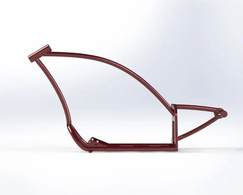
1) Chasis
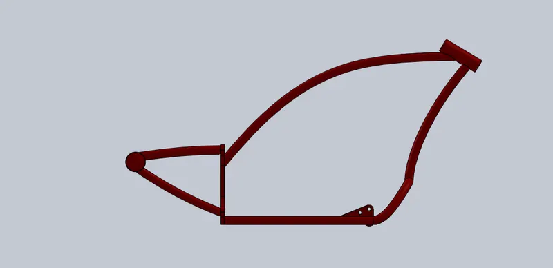
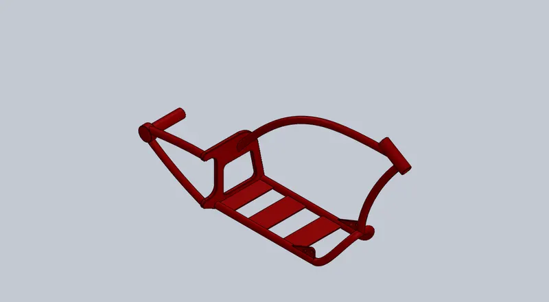
A) without Rendering
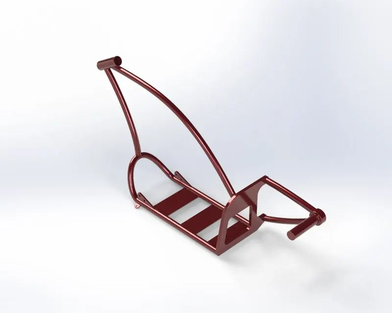
B) Rendered image
Features Used
- Offset entities
- Convert Entities
- Project Curve
- Trim entities
- Sweep boss
- Split
- Revolve Cut
- Extrude boss
- Fillet
- Combine
- Appearance
The chassis is the frame that holds the majority of the weight of the bicycle. This chassis typically makes use of splines, sweeps, project curves, split, and other design aspects. The lower tube is mirrored with respect to the mid-plane. The rear arm, which is stiff enough to hold the hub in place from just one direction, is supported by the rear plate.
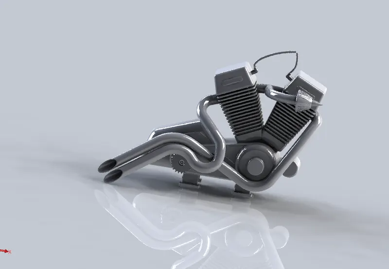
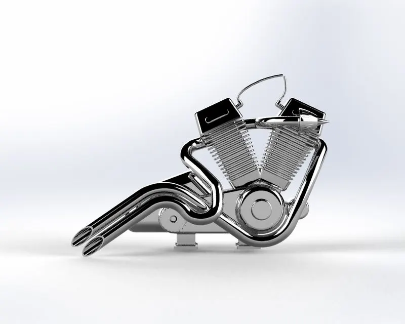
2) Engine
A) without rendering image
B) Rendered image
Features Used
- Trim entities
- Revolve Boss
- Extrude Cut
- Offset entities
- Dome
- Fillet
- Projected Curve
- Composite Curve
- Sweep boss
- Mirror
- Circular pattern
- Split
- Appearance
This motorcycle has a V-shaped engine with two exhaust pipes. Even though it is the engine block's solid modelling, it covers the majority of its components. It includes the pulleys, intake and exhaust manifolds, cooling fins, spark plug representation, and transmission unit with the transmission belt.
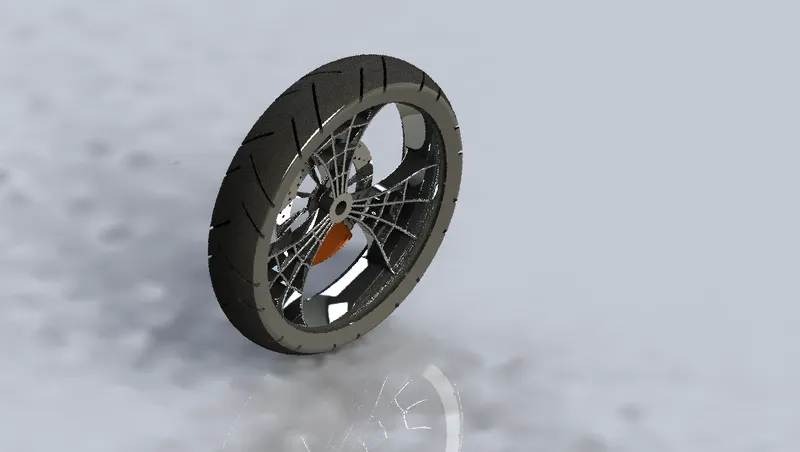
3) Front Wheel
A) without render image
B) Rendered image
Features used
- Revolve boss
- Trim entities
- sketch fillet
- Boss Extrude
- Revolve Cut
- Linear Pattern
- Chamfer
- Cut Extrude
- Circular Pattern
- Appearance
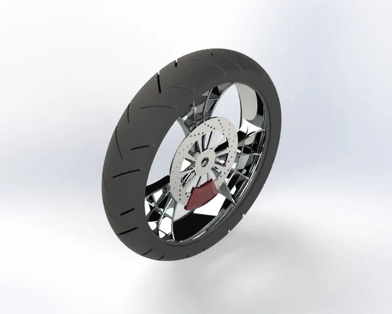
Compared to the back wheel, the front wheel is thinner. The rotor, sprocket, rim, tyre, and calliper are all single bodies built to function as a multi-body component. Circular patterns, extruded cuts, and revolves are among the most often employed features.
4) Rear Wheel
A) Without render image
B) Rendered image
Features used
- Revolve boss
- Trim entities
- Fillet
- Extrude Boss
- Planes
- Revolve cut
- Linear pattern
- Chamfer
- Fillet feature
- Extrude Cut
- Circular pattern
- Appearance
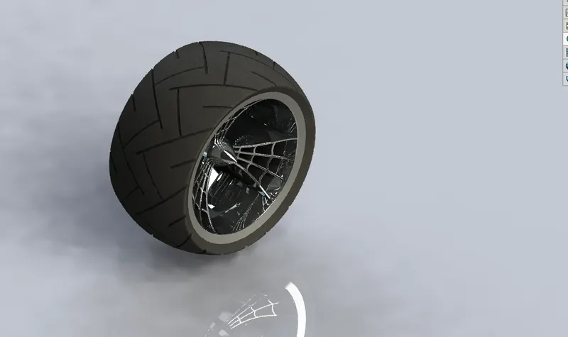
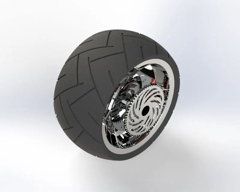
Compared to the front wheel, the back wheel is substantially thicker. It is also intended to be a multi-body part, like the front wheel, with the calliper, rotor, sprocket, rim, and tyre, all in one piece. Circular patterns, extruded cuts, and revolves are among the most often employed features.
5) Gas Tank
A) Without render image
B) Rendered image
Features Used
- Projected curve
- Trim entities
- Sweep boss
- Loft surface
- Knit surface
- Sweep Cut
- Fillet
- Appearance
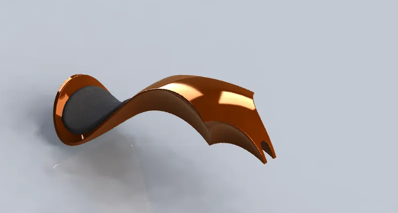
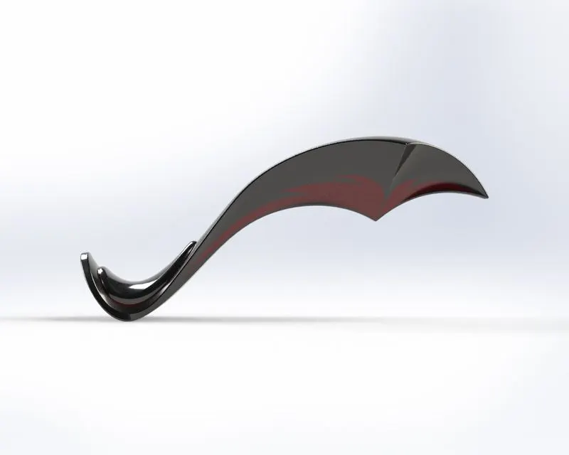
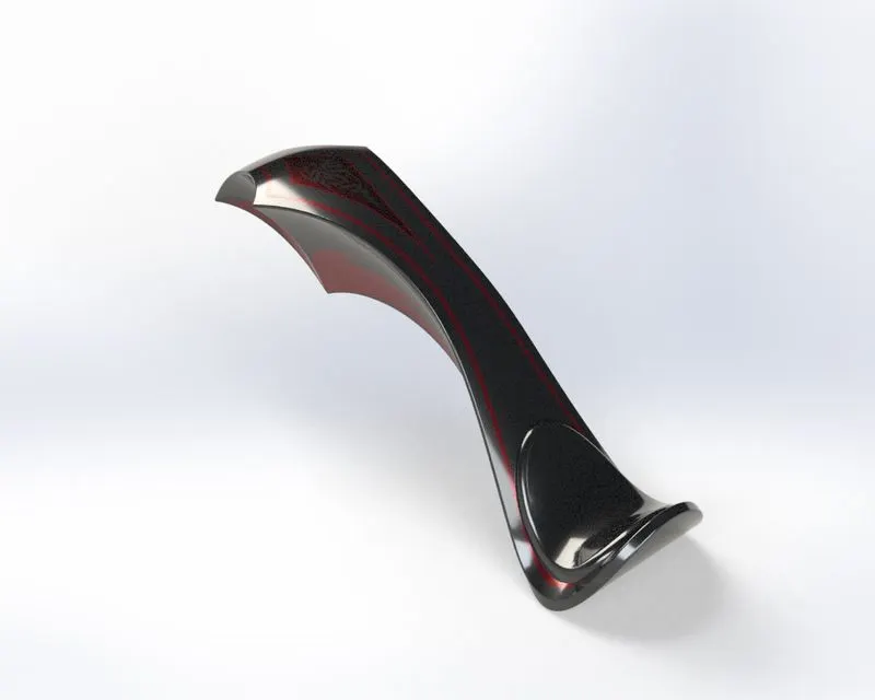
According to the information sketch, this American Chopper's fuel tank is constructed. To create a tank for the fuel inside, it has been hollowed out. Extruded surface, boundary surface, shell, and knit surface are among the features that are most frequently used. Decal applications are made, and Sienna is chosen as the appearance.
6) Oil Tank
A) Without render image
B) Rendered image
Features used
- Boss Extrude
- Combine
- Fillet
- Shell
- Appearance
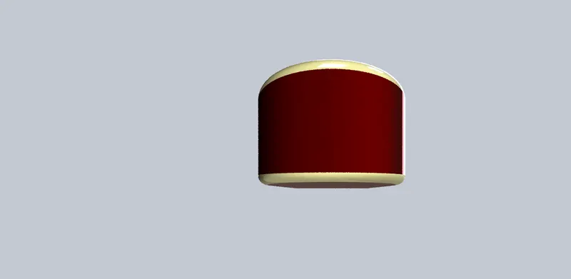
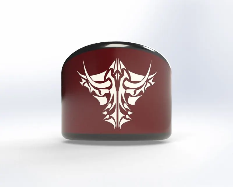
Above the engine block, which is hollow inside as well, is the oil tank. The two main features employed in this part are extrude and shell.
7) Kick Stand
A) Without render image
B) Rendered image
Feature used
- Loft boss
- Extrude boss
- Extrude cut
- Dome
- Split
- Fillets
- appearance
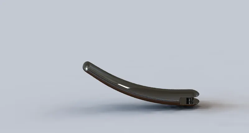
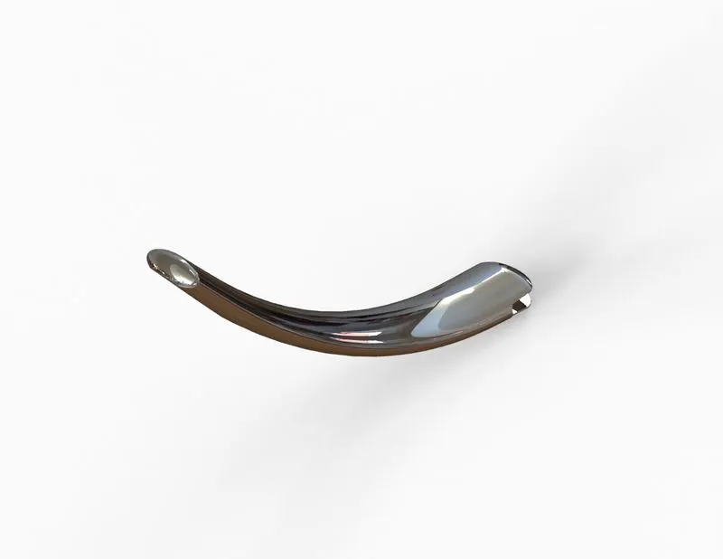
When parked, a motorcycle needs support from a kickstand to prevent tipping. These kickstands make it possible to safely get on and off your motorcycle while it is stabilised, as well as to place your motorcycle in a parking area.
8) Front Fork
A) Without render image
B) Rendered image
Features used
- Extrude boss
- Trim entities
- Revolve boss
- Split
- Move/copy bodies
- Dome
- Mirror
- Combine
- Projected curve
- Sweep boss
- Appearance
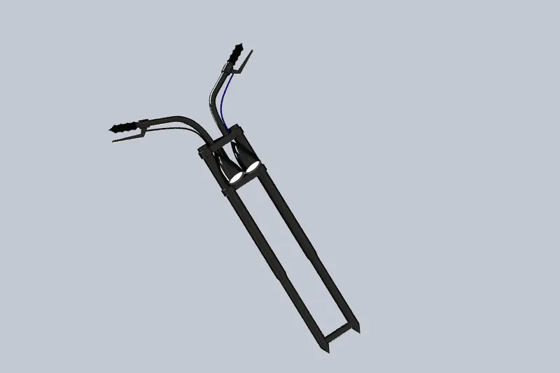
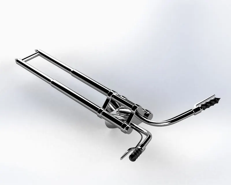
It is this American Chopper bike's most distinctive feature. It is longer than typical motorcycles, and the angle with respect to the horizontal is rather small. The handles are shorter and can be adjusted to the user's comfort. The revolving characteristics are primarily employed for this model. There are two headlights on it.
9) Pedal
A) Without render image
B) Rendered image
Features used
- Extrude boss
- Fillet
- Linear pattern
- Dome
- Chamfer
- Appearance
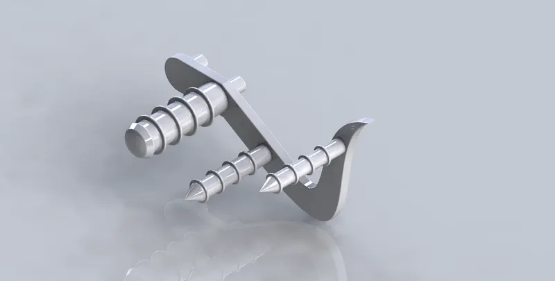
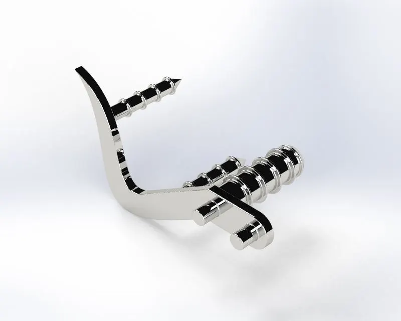
There are two pedals, left and right. The left pedal was created using the in-context features of the assembly environment, and only the right pedal was sketched and designed in the part design environment. It is intended to fit into the holes that are provided on both sides of the bottom of the chassis.
10) Chain
A) Without render image
B) Rendered image
Features used
- Trim entities
- Fillet
- Blocks
- Extrude boss
- Linear Patterns
- Appearances
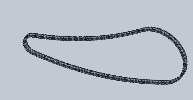
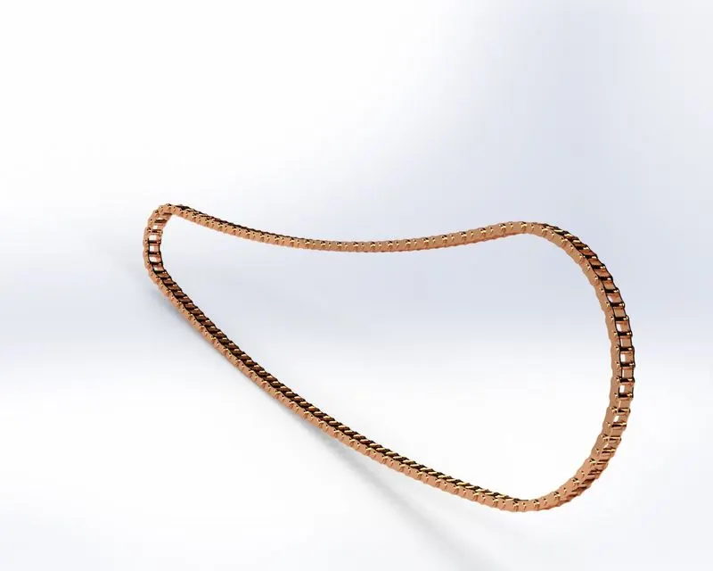
Of the entire design project, it is the most difficult component. There are 390 bodies total, including individual bodies for each of the inner plates, outer plates, and pins. The Curve driven pattern, which enables each instance of chain part to follow the curve created initially for the chain, is the key element employed in this part. It is recommended to maintain each component of this chain as a separate body since doing so would prevent it from being able to spin around the sprocket and along the curve.
11) Rear Fender
A)Without render image
B) Rendered image
Features used
- Offset Entities
- Trim Entities
- Revolve boss
- Appearances
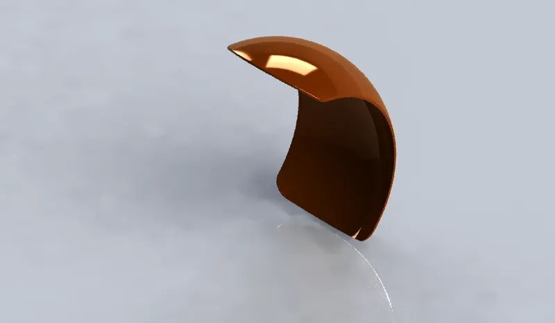
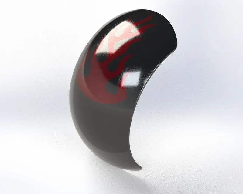
In comparison to the front fender, the rear fender is shorter but thicker. Its end is rounded like in the concept sketch rather than pointed like the front fender. The most often used tools here are revolve and split.
12) Front Fender
A) Without Render image
B) Rendered Image
Features used
- Offset entities
- Trim entities
- Revolve boss
- Dynamic Mirror
- Split
- Appearance
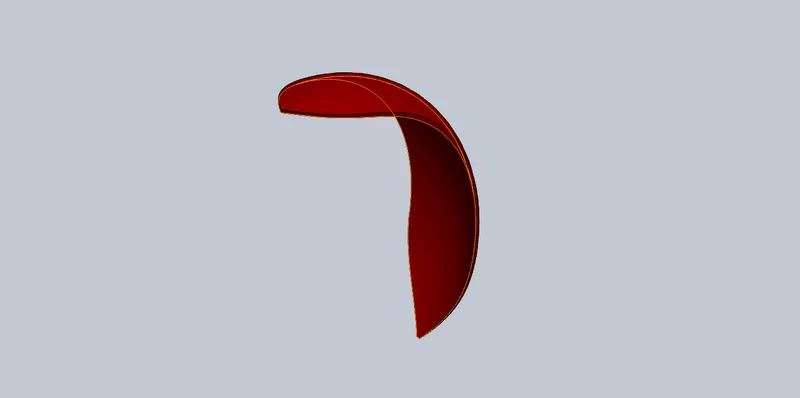
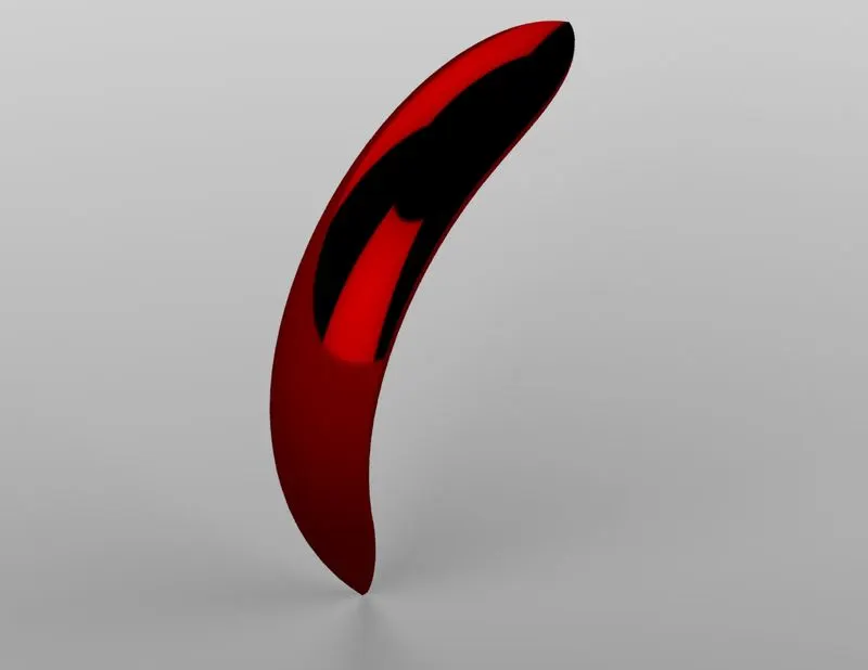
This bike's front fender was created by simply rotating the cross-section and removing material from the end to make it sharp pointed. The most often used tools here are revolve and split.
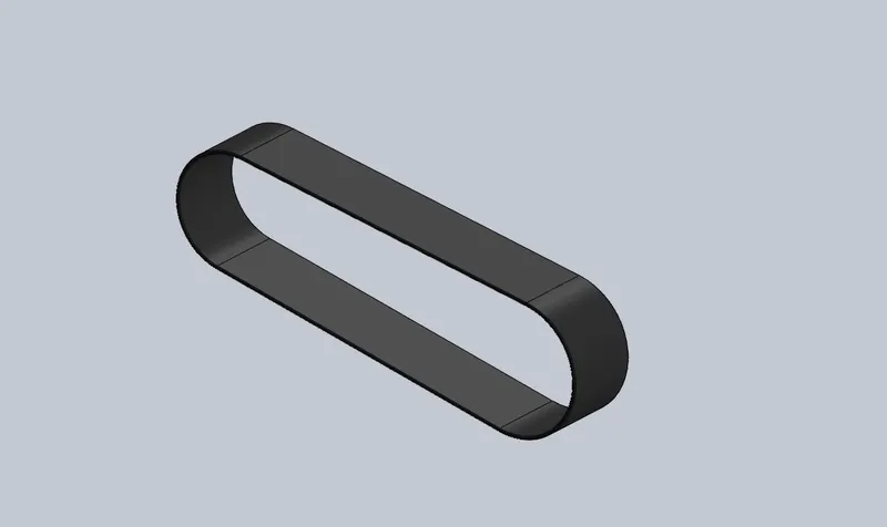
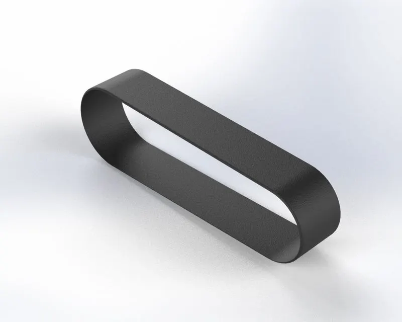
13) Transmission Belt
A) Without Render image
B) Rendered image
Features used
- Offset entities
- Extrude boss
- Fillet
- Appearances
The two pulleys made on one side of the engine block are designed to fit this transmission belt. It is a straightforward model made with just three simple tools—a line, a curve, and an extrude boss or base.
American Chopper Assembly
Putting parts together on an assembly line is the most common definition of assembly, but it can also refer to generating a finished product that fulfils its intended purpose. When a component is changed, the assembly is automatically updated, i.e. Rebuilding the document will either happen automatically or prompt the user to do so.
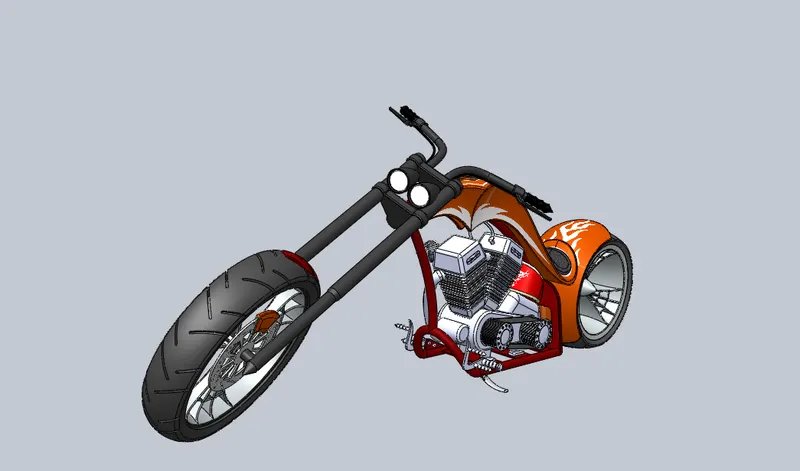
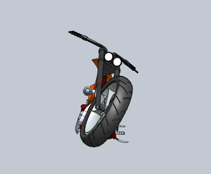
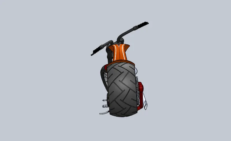
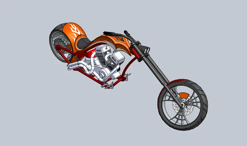
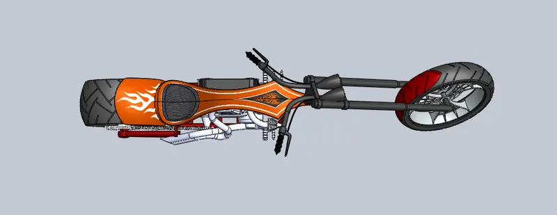
The American chopper each and every part is assembled by the use of the feature called mates. Each and every part is mate with the other or the base part with specific relation. Some relations that are used to mate the parts of American chopper are mentioned below,
- Concentric
- Coincident
- Parallel
- Tangent
- Width
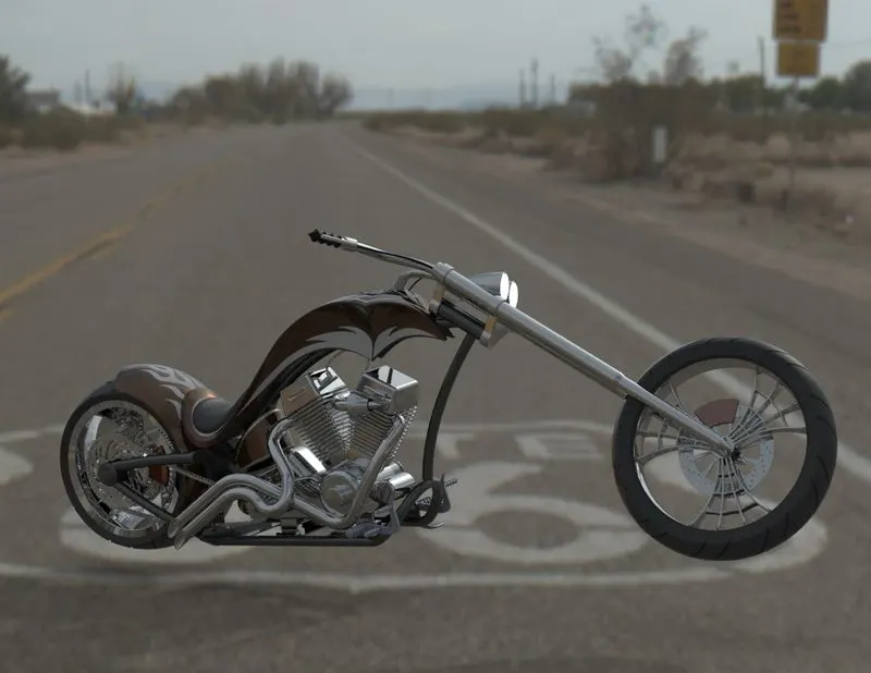
Final Render images of American Chopper
CONCLUSION
Thus, the parts of the AMERICAN CHOPPER are designed and assembled with help of SOLIDWORKS and the images are rendered using PHOTOVIEW 360 and SOLIDWORKS VISUALIZE.