Radar Mast & Final Assembly of Yacht
Sunseeker Predator Yacht Design Project using Solidworks
Objective:
- The objective of the project is to learn the Solidworks interface simultaneously sketch or model different exterior parts of the Predator Yacht.
- To assembly different parts of the Yacht in the assembly environment.
- To create the Photorealistic model of the chopper and render the model using Solidworks Photoview 360 and Solidworks Visualize
Introduction about the Sunseeker Predator Yacht
Predator Yacht is the superyacht built in 2008 at Dutch shipyard Royal De Vries Aalsmeer. The interior design of the predator was done by Bannenberg Designs and the exterior by De Voogt Naval Architects.
The hull of the yacht is steel, with the superstructure made of the aluminium. The yacht is Lloyd’s registered, issued by Cayman Islands.
The length of the yacht is 238.8 ft and the beam is 37.4 ft. The draught of the Predator is 12.1 ft. The main engines are four MTU 16V 595 TE90 with power of 5.793HP. The predator can reach a maximum speed of over 52 km/h while the cruising speed is 37km/h.
Design Tool: Solidworks
In this project the Sunseeker Predator Yacht was taken as a conceptual model, to understand the 3D modelling methodology of Solid modelling and Surface modelling. Each and every part of the yacht was designed and modelling using SOLIDWORKS. Then the modelled parts were assembled by adding proper mates and constraints to create the Photo-Realistic rendered image of the Yacht.
The SOLIDWORKS is a mechanical design automation application that lets designers quickly sketch out ideas, experiment with features and dimensions, and produce models and detailed drawings.
Photoview 360 is a SOLIDWORKS add-in that produces photo-realistic rendering of SOLIDWORKS models. The rendered image incorporates the appearance, lighting, scene and decals included with the model.
SOLIDWORKS visualize is photo-realistic rendering tool that utilizes our CAD data to create magazine quality images or commercial quality animations.
Design Methodology:
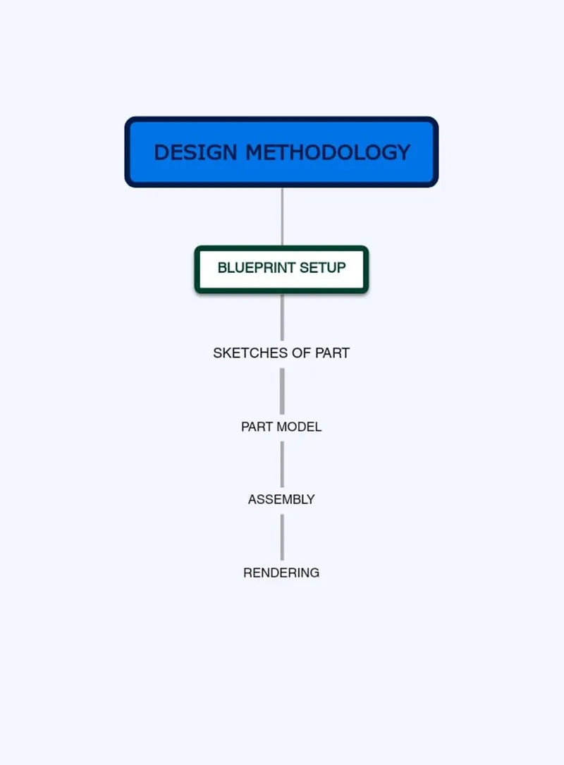
Figure: Design Methodology
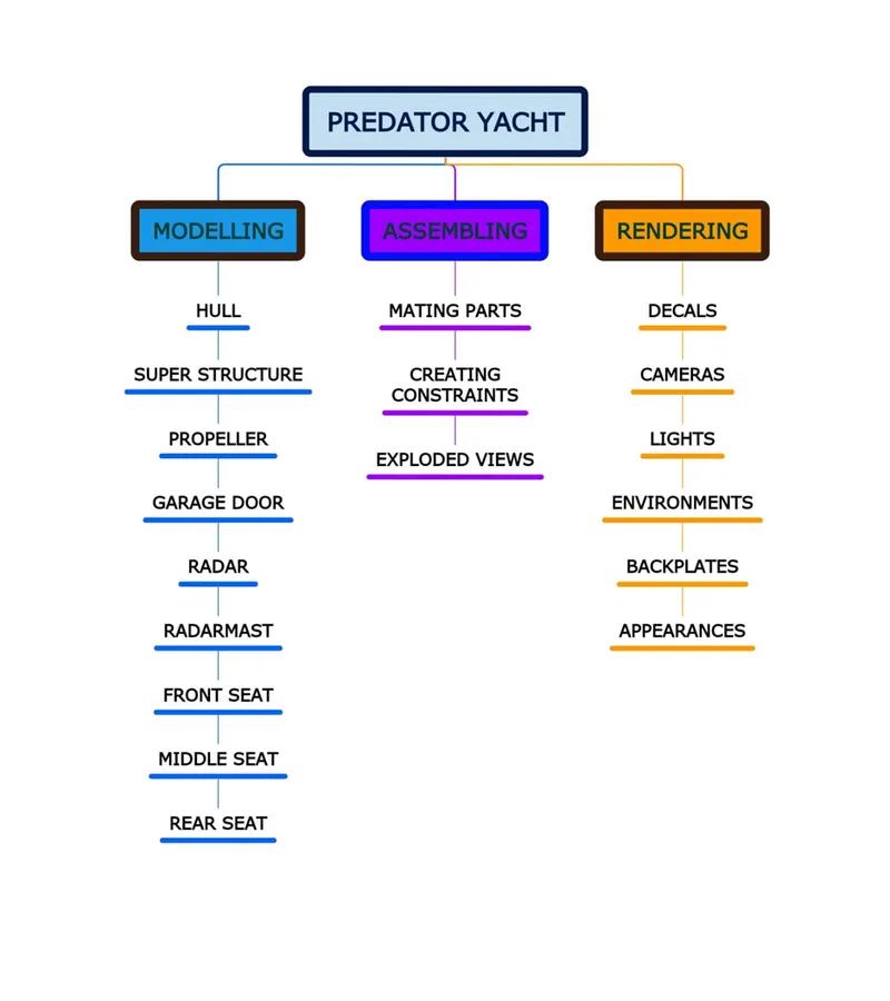
Figure 1: Flowchart of the Procedure
Introduction of Part modelling:
The American Predator yacht was modelled using part modelling. Each exterior parts are modelled separately and then assembled them together with proper connections and alignments. The individual parts involved in designing the yacht are as follows:
- Propeller
- Radar
- Blueprint setup
- Hull
- Garage Door
- Front seat
- Middle seat
- Rear seat
- Superstructure
- Radar mast
Part modelling:
Modelling in general means to create a visual prototype of an item. The 3D part is the basic building block of any large-scale design. Using parameters, we determine the shape and the geometry of the solid metal or the assembly. Parameters include numerical values such as length, radius and geometry as well as horizontal, vertical, tangency etc., Some features such as extrude boss, extrude cut, loft, revolve, fillet, chamfer, surface extrude, surface extend, surface loft, surface trim etc., are used in converting 2D sketches to 3D models and determine the shape of the model as required by the user.
File format in Solidworks: .SLDPRT
Description:
Solid modelling of all the parts of the American Predator yacht and its sketches as well are explained briefly as follows:
- Blueprint Setup
A blueprint is a reproduction of the technical drawing or engineering drawing using a contact print process on the light sensitive sheets. A blueprint is a guide for making something, it’s a design or pattern that can be followed.
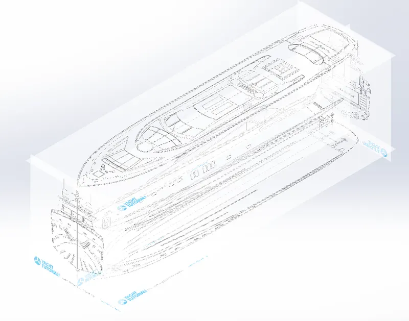
Figure 2: Blueprint Setup
Commands Used:
- Sketch Tool
- Reference Plane
- Transparency
Procedure:
- Begin with the new sketch on the Front plane and using the sketch tool setup the Front view blueprint of the Yacht.
- Change the dimensions and the position of the blueprint as x = -5776mm and y = -938mm.
- Select the “Full image” in the Transparency tab and change the transparency into 0.4 and rename the sketch as BLUEPRINT_FORNTVIEW.
- Create a new sketch on the Right plane and using the sketch tool setup the Side view of the blueprint of the yacht.
- Change the dimensions and the positions of the blueprint as x = -463mm and y = -940mm.
- Select the full image in the transparency tab and change the transparency into 0.40.
- Increase the plane size as the picture size and finally rename the sketch as “BLUPRINT_SIDEVIEW”
- Create a new sketch on the Top plane and using the sketch tool setup the Bottom view of the blueprint of the yacht.
- Change the dimensions and the position of the blueprint as x = 5646mm and y = - 440mm.
- Select the full image in the transparency tab and change the transparency into 0.40
- Finally, rename the sketch as the “BLUEPRINT_BOTTOMVIEW” and rename the plane as Bottom plane.
- Create a new plane by using Reference geometry tool and select the front plane as the reference and apply an offset distance of 32920mm.
- Rename the newly created plane as “Back Plane”.
- Create a new sketch on the Back plane and using the sketch tool setup the Back view of the blueprint of the yacht.
- Change thee dimensions and the position of the blueprint as x = - 5774mm and y = - 938mm
- Select the full image in the transparency tab and change the transparency into 0.40
- Flip horizontally the image to make sure that the ship horns are on the same side as in BLUEPRINT_FRONTVIEW.
- Rename the sketch as the “BLUEPRINT_BACKVIEW”
- Create a new reference plane by using reference geometry tool and select the Bottom plane as the reference and apply an offset distance of 1000mm.
- Rename the newly created plane as “Top Plane”
- Create a new sketch on the Top plane and using the sketch tool setup the Top view of the blueprint of the yacht.
- Change the dimensions and position of the blueprint as x = 5646mm and y = -440mm
- Select the full image in the transparency tab and change the transparency into 0.40
- Rename the sketch as BLUEPRINT_TOPVIEW.
- Rename the right plane as the Mid plane and change the order of the planes.
- Finally, save the file as “BLUEPRINT_SETUP”.
2. Propeller
A propeller is a device with a rotating hub and rotating blades. It transforms rotational power into linear thrust by acting upon a working fluid, such as water or air. The rotational motion of the blades is converted into thrust by creating a pressure difference between the two surfaces.
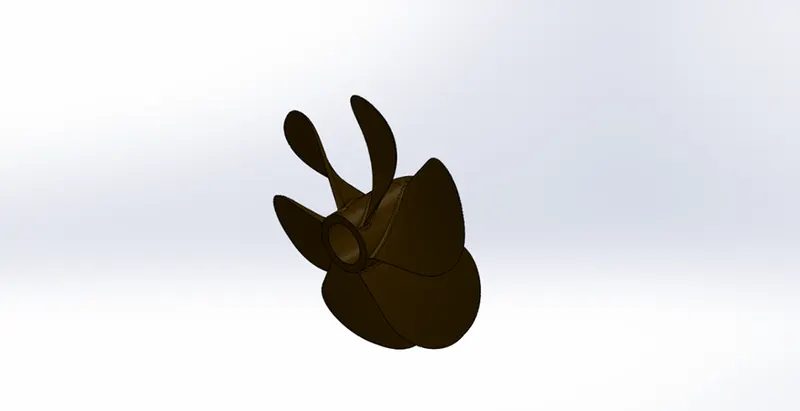
Figure 3: Propeller
Commands Used:
- Line
- Spline
- Revolve Boss
- 3-point corner rectangle
- Reference geometry
- Loft boss
- Extrude cut
- Fillet
- Circular pattern
Procedure:
- Begin with creating a new sketch on the right plane and sketch three straight lines.
- Sketch 350mm horizontal line such that it should be placed on the middle axis of the right plane.
- Continue sketching 80mm line perpendicular to 350mm line and then complete the sketch by sketching of 200mm horizontal line.
- Draw a spline between the 200mm line and 350mm line and add tangency relation between the 200mm line and spline.
- Apply Revolve boss feature by selecting the 350mm line as the axis of the revolution.
- Create a new sketch on the top plane and sketch a rectangle of 230mm length and 12mm breadth by using the 3 point corner rectangle command.
- Change the dimensions of the rectangle as shown in figure
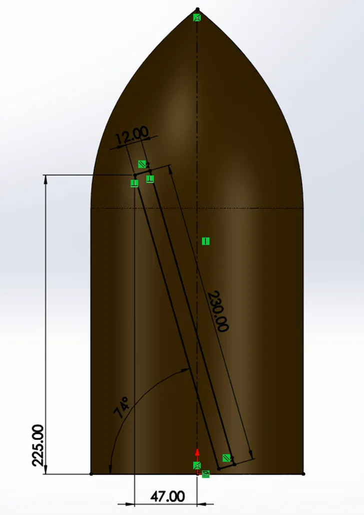
Figure 4: Sketch of the rectangle on the Top plane
- Create a new plane using reference geometry tool and selecting the Top plane as the reference plane and apply an offset distance of 360mm.
- Create a new sketch on the newly created plane and draw a rectangle of length 400mm and breadth 12mm using 3 point corner rectangle tool. Change the dimensions of the rectangle as shown in figure
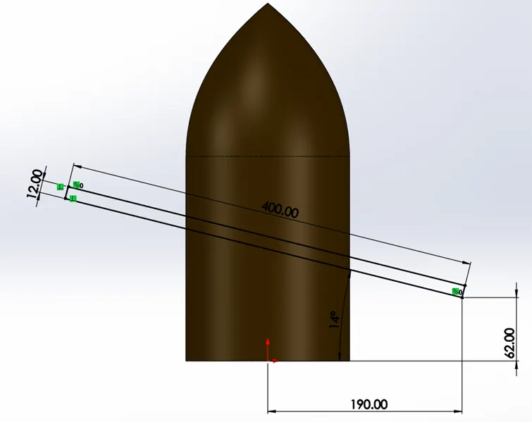
Figure 5: Sketch of rectangle on the new plane
- Create a solid loft by selecting Loft Boss feature and select the sketch 2 and sketch 3 in the profile box.
- Create a fillet of radius of 135mm on the edges of the loft using fillet tool.
- Next, create a new sketch on the surface of the axle and draw a circle of 114mm diameter.
- Apply an extrude cut of 210mm depth inwards with the above sketch.
- Apply fillet of 30mm radius on the front edge of the blade of propeller and also apply fillet of 10mm radius on the edge of the axle and the blade.
- Using Circular pattern tool, mirror the propeller blades by selecting the axle surface as the pattern axis and apply total angle of 360⁰ up to 6 instances with equal spacing.
- Change the appearance of the propeller by changing the colour to the custom brown by changing the RGB numbers to 71,45,0.
- Finally save the file.
3. Radar
Radar is the detection system that uses radio waves to determine the range, angle or velocity of the object. Radio waves (pulsed or continuous) from the transmitter reflect off the object and return to the receiver, giving information about the object’s location and speed.
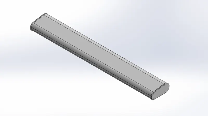
Figure 6: Radar
Commands Used
- Line
- Boss extrude
- Fillet
- Offset entities
- Sketch entities
- Extrude cut
- Point
- Mirror
- Text
- Split line
Procedure
- Begin with new sketch on the right plane and draw four lines as shown in the figure
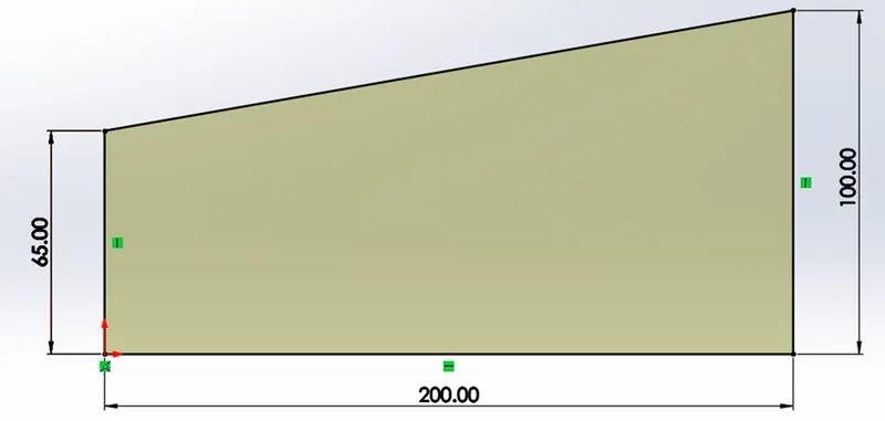
Figure 7: Sketch on the right plane
- Apply boss extrude to the depth of 700mm.
- Apply fillet of 46mmand 20mm radius is applied on the required edges.
- Create another fillet of 30mm radius on the required edges
- Select the surface opposite to the right plane and begin new sketch on it
- Apply offset entities on the entire surface and change the offset distance to 3mm outwards.
- Create Boss extrude to the depth of 10mm on the above sketch.
- Begin a new sketch on the same surface as selected before. Select the entire surface and apply offset entities feature on it.
- Change the Offset distance to 10mm inwards and then convert the entire offset line in to the construction line. Finally, continue by drawing a circle of 8mm diameter at the vertical distance of 60mm from the origin.
- Apply boss extrude feature on the previous circle sketch to the depth of 3mm.
- Apply fillet of 3mm radius on the upper edge of the extruded circle.
- By selecting the filleted surface of the extruded circle create a new sketch on it.
- Sketch a polygon of 3.5mm width a shown in figure
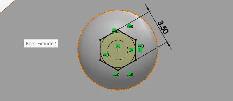
Figure 8: Sketch of polygon
- Apply extrude cut to the depth of 1.5mm on the above sketch
- Next, sketch three points with dimensions with respect to the origin on the surface as shown in figure
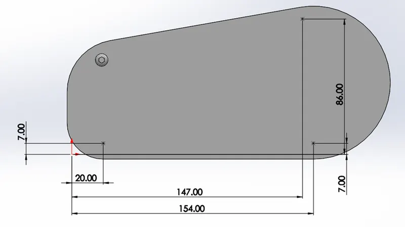
Figure 9: Sketch of the points on the surface
- Use Sketch driven pattern feature and select the above sketch as the reference sketch and select the required components as the feature to be mirrored.
- Apply a fillet of 3mm radius on the required edges.
- Mirror the radar by apply the mirror feature and select the right plane as the mirror face and also select the entire body of the radar to be mirrored.
- Next, select the bottom surface and begin a new sketch on it. Sketch a circle of 60mm diameter at a vertical and horizontal distance of 80mm and 710mm respectively.
- Apply extrude cut on the above sketch to the depth of 40mm
- Apply a fillet of 3mm radius on the circular edges of the extrude cut.
- Create a new sketch on the required surface of the radar and draw a horizontal centreline of 675mm and its left endpoint at a distance of 337.5mm from the origin and vertical distance between the origin and the line be 17mm.
- Use sketch entities feature add text on the radar and select the horizontal centreline as the reference line. Type a text to project on the read on the Text box.
- Change the Font to Century Gothic and Font style to Bold with changing the Text height to 60mm.
- Apply split line feature and choose the Projection option and select the current sketch as the sketch to project and the surfaces as Faces to split.
- Change the colour of the Radar to the white and change the colour of the text to a custom dark grey by changing the RGB numbers to 70,70,70.
- Finally, save the file.
4. Hull
A hull is watertight body of a ship, boat, or flying boat. The hull may open at the top (such as dinghy), or it may be fully or partially covered with a deck. Atop the deck maybe be deckhouse and other superstructures, such as funnel, derrick or mast. The line where the hull meets the water is known as Waterline.
Hull come in many varieties and can have composite shape, but are primarily grouped as follows:
- Chined and hard-chined
- Moulded, round bilged or soft-chined
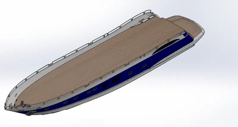
Figure 10: Hull
Commands
- Line
- Spline
- Project Curve
- Power trim
- Boss Extrude
- Surface Loft
- Surface Fill
- Surface Extrude
- Extrude Cut
- Angle-Distance Chamfer
- Distance-Distance Chamfer
Procedure
- Open the Blueprint_Setup file and save as the file as Hull.
- Hide the Blueprint_Frontview, Blueprint_Backview and Blueprint_Topview sketches
- Begin, with creating a new sketch on the Bottom plane. Draw a horizontal line and connect its right endpoint to the Backplane.
- Add the vertical dimension of 3236mm with respect to the origin and left endpoint be 15783mm away from the origin.
- Draw a spline with one midpoint and connect the endpoint of the spline with the origin and apply equal curvature relation between the horizontal line and the spline.
- Also, add vertical relation on the left endpoint arrow of the spline. Pull at the two arrows and the midpoint of the spline to create the exact curve of the blueprint.
- Create a new sketch on the Midplane and draw a straight line with vertical dimension of 6051mm and 5173mm on the left endpoint and right endpoint of the line.
- Continue with creating the second part of the edge with the a spline with two midpoints and draw a line such that the right endpoint of the line is connected to the Back plane and left endpoint of the line is connected to the previous spline and add dimensions as shown in figure.
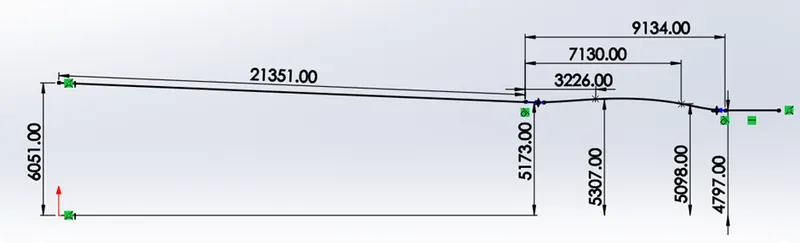
Figure 11: Sketch on the Midplane
- Apply tangency relation on the both sides of the spline with respect to the lines on the both sides of the spline.
- Using Projected curve feature, create a curve by selecting the above two sketches.
- Next, create a new sketch on the Midplane and draw a horizontal line such that right endpoint is connected to the backplane.
- Add vertical dimension of 2102mm and horizontal distance of 19065mm between the left endpoint of the line and the origin.
- Continue with creating a second part of the edge with a spline with one midpoint and add dimensions as shown in figure
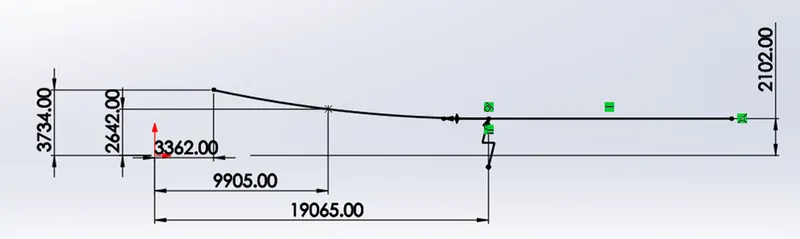
Figure 12: Sketch on the Midplane
- Apply equal curvature relation between the line and the spline.
- Next, create a new sketch on the Bottom plane and draw a spline with three midpoint and connect the right side of the spline with the Back Plane.
- Connect the left endpoint of the spline with the previous sketch by applying coincident relation between them.
- Add horizontal and vertical dimensions as shown in figure.
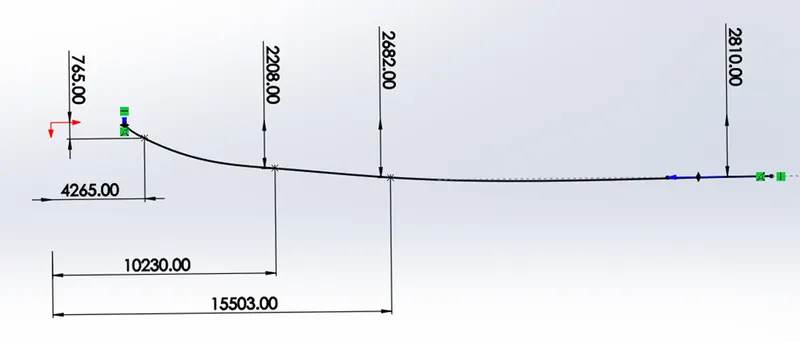
Figure 13: Sketch on the Bottom Plane
- Apply vertical relation on the right side of the spline and horizontal relation on the left side of the spline.
- Pull the arrow point of the left side of the spline to match the blueprint.
- Create a curve using Projected curve feature by selecting on the above two sketches.
- Now, create a new sketch on the Back plane and draw a spline with no midpoint.
- Apply pierce relation between the upper endpoint on the spline and the curve1 and also between the lower endpoint of the spline and curve2.
- Pull the arrow point of the lower endpoint of the spline to approach the curve on the blueprint as good as possible.
- Create a new sketch on the Midplane and draw a straight line
- Apply pierce relation between the upper endpoint of the line and curve1 and lower endpoint of the line and the curve2.
- Apply Surface Loft feature by selecting curve1 and curve2 as the profiles and above two sketches as the guide curves of the loft.
- Next, create a new sketch on the Midplane and draw a horizontal line of 20268mm length and vertical height of 1169mm with its right endpoint of the line connected with the Back plane.
- Draw, a spline and connect the right side of the spline with the horizontal line and left side of the spline with the corner of the Surface Loft1.
- Apply equal curvature relation between the horizontal line and Spline and also apply tangency relation between the spline and line of the surface loft.
- Pull the two arrow points of the spline to match the curve of the blueprint as good as possible.
- Create a new sketch on the Back plane and draw a spline.
- Apply coincident relation between the upper endpoint of the spline and the corner of the Surface loft1.
- Apply pierce relation between the right endpoint of the spline and the above sketch and pull the arrow point to approach the curve on the blueprint as good as possible.
- Using Surface loft feature, select the lower edge of the surface loft1 and sketch7 as the profiles and select the sketch8 as the guide curve.
- Next, create a new sketch on the Midplane and draw a diagonal line and connect the endpoints of the line with surface loft1 and surface loft2.
- Add horizontal dimension of 27637mm and 30853mm between the upper endpoint of the line and origin and lower endpoint of the line and the origin respectively.
- Using the Trim feature, trim the rear of Surface loft1 and Surface Loft2 by selecting the above sketch as the trim tool. Select remove selection option and choose the required surface to be removed.
- Create a new sketch on the Midplane and draw two centrelines one each at the right-side corner of the surface loft1 and surface loft2.
- Apply tangency relation between the upper centreline and the upper edge of the surface loft1 and lower centreline and the lower edge of the surface loft2.
- Draw a spline between the centreline and pull on the arrow point to approach curve on the blueprint as good as possible
- Apply Surface loft feature, by selecting the upper edge of the surface loft1 and the above sketch as the profiles. Select Tangency to face as Start constraint for the transition between the surface loft1 and the new surface loft and change the tangency length to 1.3
- Select the Normal to profile as end constraint for the transition between the Midplane and new surface loft and change the tangency length to 2.
- Next, create a new sketch on the Midplane and draw a vertical line of 1993mm at a horizontal distance of 29990mm from the origin. Continue, by drawing a line of 1000mm length perpendicular to the above drawn line.
- Apply surface extrude feature on the above sketch to the depth of 5000mm
- Using the trim feature, select the above surface extrude as the trim tool. Select the remove selection option and choose the required surfaces to be removed.
- Apply the Surface knit feature, select the surfaces to be knitted.
- Apply trim feature, select the body as the trim tool and select the surfaces to be removed.
- Create a new sketch on the Midplane and draw a straight line such as the end points are connected to the upper edge of the surface body
- Apply Surface fill option on the above sketch by selecting the required edges.
- Knit all the surfaces of the Hull using Surface Knit feature.
- Using the Surface fill option, select the required edges and solidify the model
- Select the required surfaces and apply the Shell feature on it to the thickness of 120mm
- Create the new sketch on the Midplane and draw a line of 33911mm with vertical length of 4262mm and 5156mm at the left endpoint and right endpoint respectively.
- Apply Offset entities feature and select the five outer edges of the hull and apply the offset distance of 50mm inwards.
- Use power trim tool and remove the unwanted end of the lines.
- Apply Boss extrude and change the blind direction up to the next.
- Create a new sketch on the Midplane and draw the lines with dimensions as shown in figure
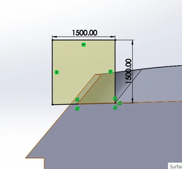
Figure 14: Sketch on the Midplane
- Use Extrude cut feature, apply to the depth of 2734mm inwards
- Next, sketch lines and spline with dimension as shown in figure in Midplane
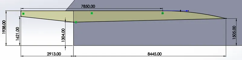
Figure 15: Sketch on the Midplane
- Using Boss extrude, extrude the above sketch to the depth of 3070mm
- Create a new sketch on the Bottom plane, draw lines and splines with dimensions as shown in figure.
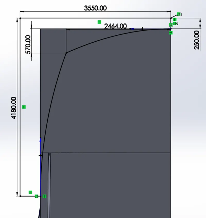
Figure 16: Sketch on the Bottom plane
- Add horizontal relation on the right endpoint of the upper spline and vertical relation on the bottom endpoint of the lower spline.
- Apply extrude cut to the depth of 3200mm by using the extrude cut feature.
- Create a fillet of radius of 1000mm on the required edge.
- Apply angle distance Chamfer of 50mm depth and angle of 45⁰ on the required edges.
- Also, apply Distance-Distance chamfer of 300mm and 150mm on the edges as required
- Next, create a fillet of radius of 100mm and 30mm on the required edges.
- Apply a fillet of 100mm radius on the edges
- Create a new reference plane by using reference geometry and selecting the Midplane as the first reference and change the offset distance to 5000mm.
- Create a new sketch on the newly created plane and draw a line with horizontal distance of 2085mm and 7000mm from the corner of the body to the left endpoint and right endpoint respectively.
- Apply parallel relation between the line and the upper edge of the body and change the vertical height to 190mm
- Draw a spline without midpoint and connect its endpoints with ends of the lines.
- Click on the one of the endpoints of the spline and drag at the arrow point to change the curve and approach the curve on the blueprint as good as possible. Do the same thing for the other side of the spline.
- Create a extrude cut, change the direction 1 to the offset from surface and select the appropriate face and change the offset distance to 38mm.
- Click on the reverse offset option to make sure that the Extrude cut is directed inwards the body.
- Create a fillet of 50mm and 35mm radius on the appropriate edges of the body
- Next, create a new sketch on the newly created plane and also switch the display style to wireframe to make the blueprint visible in the hull.
- Draw four lines to make a rectangle as shown in blueprint to make a window and select the four lines and click on the fix relation on the lines.
- Add a sketch fillet of radius of 50mm on the corners of the rectangle.
- Using Linear pattern feature, create a linear pattern for other windows and change the distance to 510mm with instance up to 6. Also change the angle to 178 to reproduce the window on the blueprint as good as possible.
- Add fix relation on the lines of the windows reproduced through linear pattern
- Apply extrude cut feature, select the offset from the surface with depth of 50mm. Click on the reverse offset to make sure the extruded cut is directed inwards the body.
- Create a fillet of radius of 20mm on the edges of each window.
- Create a new sketch on the newly created plane and reproduce one of the portholes as shown in figure using the straight slot icon and fix the sloth using the fix relation.
- Copy and paste the portholes as shown in blueprint by selecting the slot as the entities to copy.
- Define all the portholes by adding the fix slot relation on the all the portholes.
- Using the extrude cut option, Select the Offset from the surface option to the depth of 50mm on the appropriate face. Click on Reverse offset option to make sure that the extruded cut is directed inwards the body.
- Create a new plane using Reference geometry feature and selecting the point of one of the portholes as First reference and edge of the portholes as the second reference.
- Create a circle of 40mm diameter on the newly created plane.
- Create a 3D sketch, select the outer edges of the portholes and convert them into entities by using convert entities option.
- Create a solid sweep using Sweep icon, selecting the 2D circle as the profile and 3D sketch as the path.
- Create another sketch on the Plane1, draw the two cable holes with the Slot feature and change the slot dimension to 180mm and 400mm as vertical height and horizontal distance respectively
- Use fix sloth option to fix the sketch.
- Draw rear cable hole as rectangle of lenght750mm and breadth 100mm with vertical height of 111mm
- Click on the surface of the big porthole and convert it into entities using convert entities.
- Next, continue with drawing a horizontal line of 850mm length and 100mm vertical line perpendicular to it.
- Using Power trim tool, remove the unwanted
- Apply extrude cut through all on the body through above sketch
- Using Reference geometry feature, create a new plane by selecting a point of one of the cable holes as first reference and edge of the cable holes as the second reference.
- Create a sketch of circle of 25mm diameter on the newly created plane.
- Next, create a 3D sketch by selecting the outer edges of the cable holes and convert them into entities using convert entities feature.
- Create a solid sweep using sweep feature and selecting the 2D circle sketch as the profile and 3D sketch as the path
- Same steps to be repeated on the other cable holes.
- Next, Create a new sketch on the top plane as shown in figure
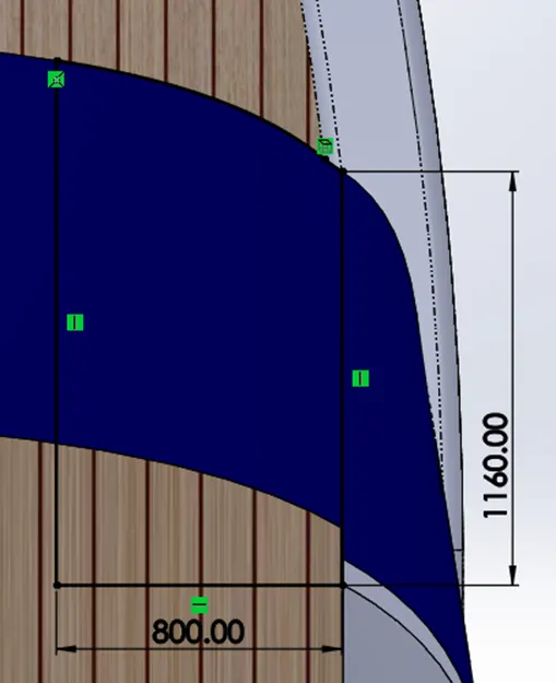
Figure 17: Sketch on the Top plane
- Create a Extrude cut using Extrude cut feature up to the surface by selecting the appropriate face.
- Select the surface and create a sketch of steps as shown in figure
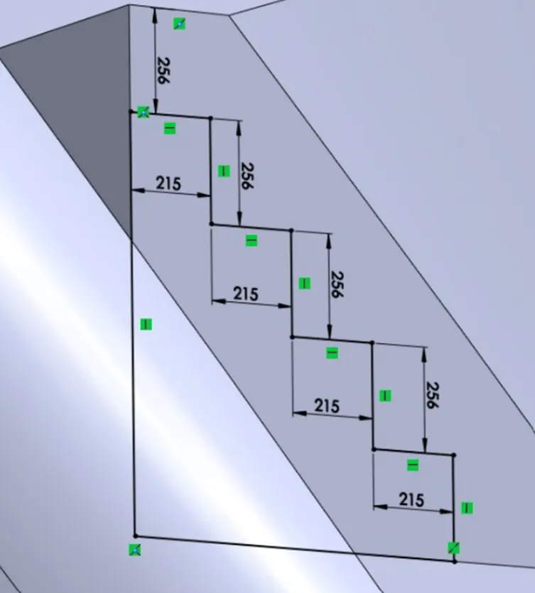
- Create Boss extrude on the above sketch and change the blind direction to up to next.
- Select the surface and sketch as the following with dimensions
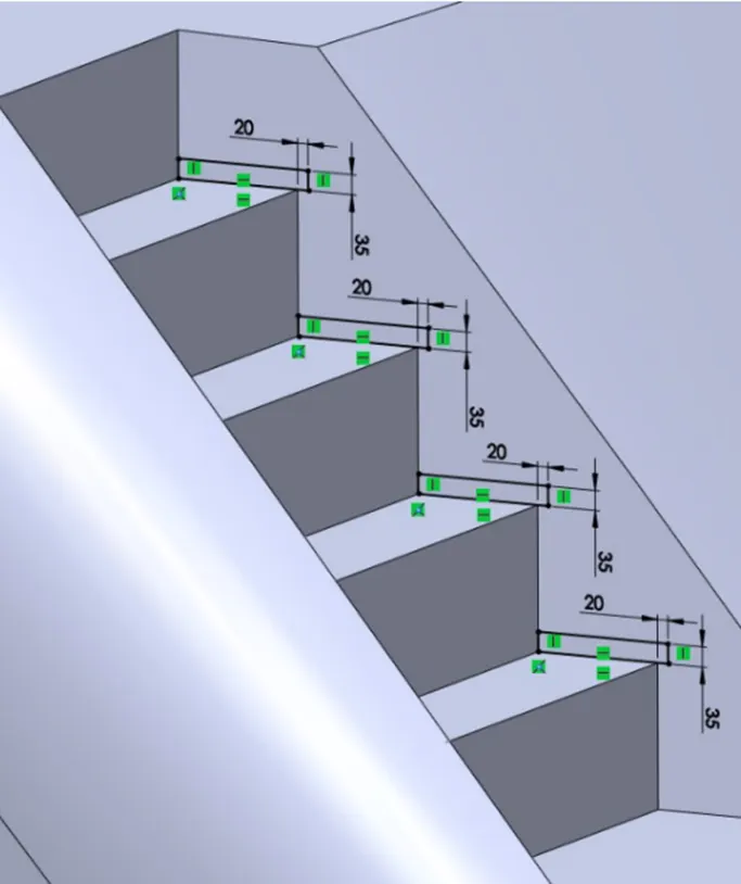
Figure 19: Sketch on the surface
- Create a extrude up to surface to the opposite surface and select the four rectangles as selected contours.
- Select the surface as shown in figure and click on the 2D sketch icon to make the new sketch
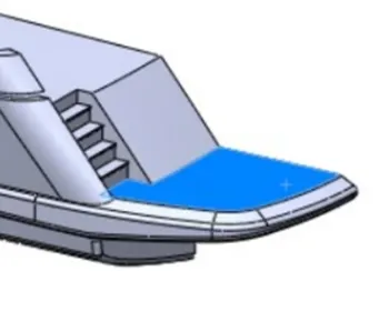
Figure 20: Surface selected to create a sketch
- Click on the Normal to option to rotate and zoom the model to normal to the selected plane.
- Draw splines with no midpoint such that the left endpoint of the upper spline connected to Midplane and change the curves of the spline as shown on the blueprint.
- Add the Horizontal relation to the left endpoint of the upper spline.
- Offset the two edges by Offset entities feature and change the offset distance to 120mm inwards.
- Close the ends of the edges with a line and trim the detail
- Select one of the endpoints of the upper spline and add fix relation on it to define the sketch.
- Create a boss extrude to the thickness of 10mm.
- Select the blue surface and create a new sketch as shown in figure.

Figure 21: Surface selected for creating new sketch
- Convert the curves of the surface through convert entities feature and draw two vertical lines on the left side at 60mm apart from each other.
- Trim the right side of the two curves
- Create a Boss extrude to the thickness of 10mm.
- Create a fillet of 10mm radius on the required edges
- Select the appropriate surface and create a sketch using lines with dimensions as shown in figure.
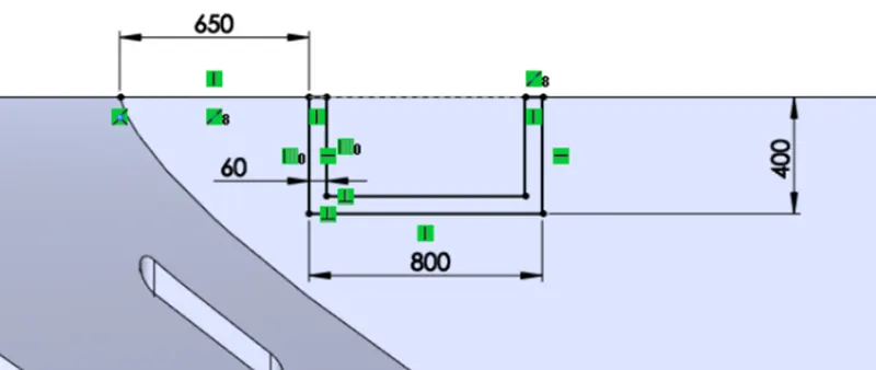
Figure 22: Sketch on the Surface
- Create Boss extrude to the thickness of 10mm for the above sketch
- Create a fillet on the eight edges of the extrude boss to the radius of 10mm
- Using Reference Geometry feature, Create a new plane by selecting the Bottom plane as the First reference and change the offset distance to 3000mm
- Next, create a new sketch on the new created plane. Draw three splines without any midpoints as shown in blueprint and Click on an endpoint of one of the splines and pull the arrow to create the exact curve of the blueprint. Do this for all the splines
- Offset the three edges by Offset entities feature and change the offset distance to 120mm
- Close the three curve shapes with a line at the left side and right side of each curve. Draw two lines to connect each offset with the original splines.
- Select the three curves and add fix relation to define the sketch.
- Create a Boss extrude to offset from the surface and select the appropriate face with offset distance of 75mm. Click on the reverse offset option to make sure that the extrude cut is directed inwards the body.
- Create a distance-distance chamfer on the edges of the extrude with distance1 = 300mm and distance2 = 100mm.
- Create another distance-distance chamfer on the appropriate edges of the extrude with distance1 = 60mm and distance2 = 100mm
- Create a fillet of 800mm and 60mm radius on the required edges
- Create a new sketch on the selected surface as shown in figure

Figure 22: Surface selected for sketching
- Draw two lines and two circles with dimensions and trim the inner sides of the circles as shown in figure
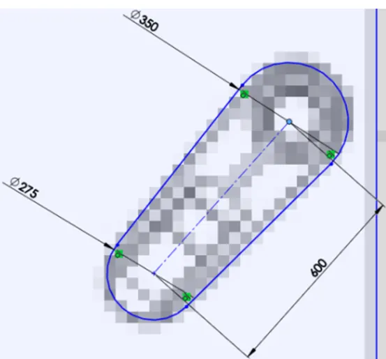
- Create a boss extrude on the above sketch to the thickness of 30mm
- Create a new plane using Reference geometry and select the three points as the references as shown in figure
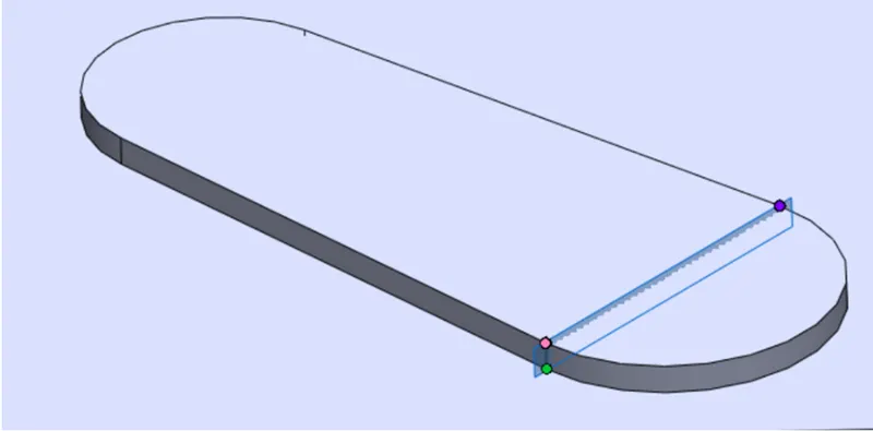
Figure 24: Vertex references for the plane
- Create a 2D sketch on the plane using the lines and add the dimensions as shown in figure
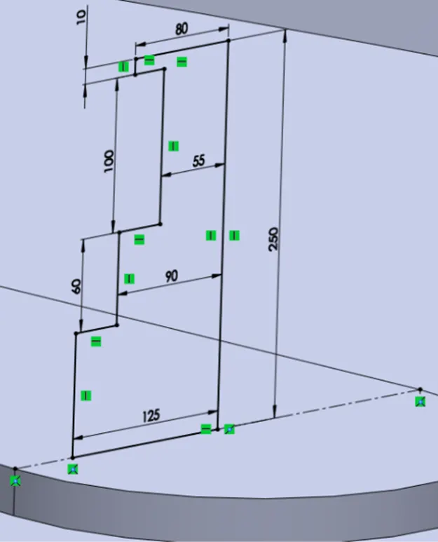
Figure 25: Sketch on the new plane
- Using Revolve feature, create a revolve by selecting 250mm vertical line as the axis of revolution.
- Create an Angle distance chamfer on the upper edge of the revolve of 8mm and angle of 45⁰
- Using Dome tool, create a Dome on the upper surface and set the dome distance to 15mm
- Create a new plane using reference geometry as shown in figure
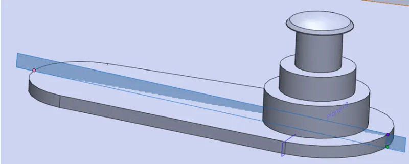
Figure 26: References for new plane
- Create a 2D sketch on the new plane and draw a centreline such that one of the endpoints of the centreline has pierce relation with the one of the arc edges.
- Draw the lines and circle with dimension as shown in figure
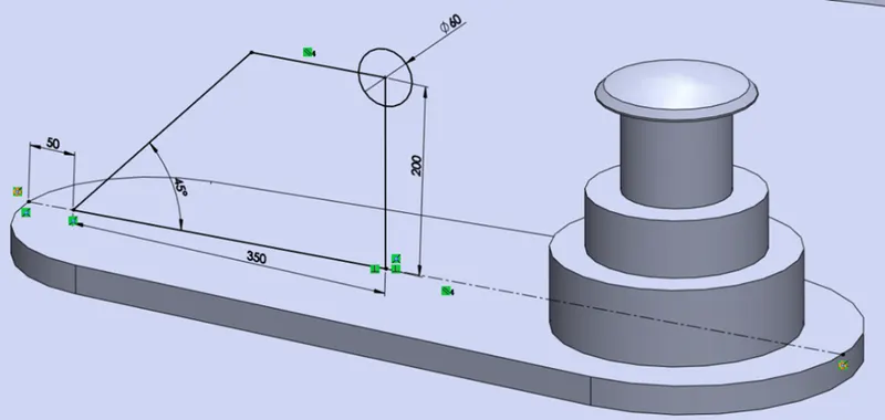
Figure 27: Sketch on the new plane
- Apply Boss extrude to Midplane direction to the thickness of 200mm
- Select the surface and begin new sketch on it as shown in figure
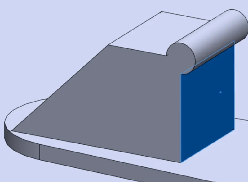
Figure 28: Surface selection for the sketch
- Draw a corner rectangle on the selected surface such that its sides are 25mm apart from the sides of the extrude just not on the bottom
- Apply extrude cut feature, create an extrude cut to the depth of 180mm with its direction directed inward.
- Create a fillet of 10mm and 5mm radius on all the appropriate edges
- Next, begin the sketch on the surface as shown in figure
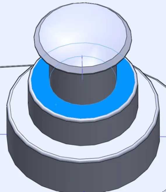
Figure 29: Surface selection for the sketch
- Draw a circle of 132mm diameter on the surface as selected above.
- Create a Helix/Spiral selecting the circle sketch just made and choose constant pitch option. Set the pitch length to 22mm and number of revolutions to 3.65 with start angle as 90⁰ in clockwise direction.
- Create a new plane by selecting upper endpoint of the Helix/Spiral as first reference and selecting Helix/Spiral as second reference using reference geometry
- Create a sketch of circle of 20mm diameter on the newly created plane and add pierce relation between the circle and the Helix/Spiral
- Create a solid sweep by selecting the circle sketch as the profile and Helix/Spiral as the path using Sweep tool
- Select the upper circular surface of the Solid Helix/Spiral and begin the sketch
- Convert the outer edges of the surface into entities and draw a vertical centreline between it.
- Create a new plane on the upper circular face of the solid Helix/Spiral by selecting Vertical centreline as the first reference and circular face as the second reference by using Reference geometry
- Next, begin creating new sketch on the new plane and draw a spline without any midpoints such that the right endpoint of the spline is coincident to the Upper circle edge of the Helix/Spiral.
- Apply horizontal relation on the arrow of the right endpoint of the spline and add horizontal dimension of 480mm and vertical dimension of 180mm on the spline.
- Create a solid sweep by selecting the circle as the profile and the spline sketch as the path.
- Create a sketch on the selected surface as shown in figure
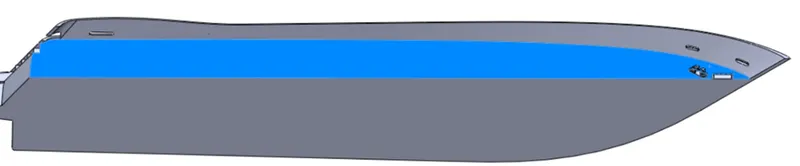
Figure 30: Surface selection for sketch
- Cerate one of the portholes with the Slot feature and change the slot height to 120mm and slot width to 200mm. Add Fix sloth relation to define the sloth
- Create a Boss extrude to the thickness of 20mm for the above sloth sketch.
- Select the upper face of the extruded Portholes and begin the sketch. Draw circle of 45mm diameter each on the arc centre of the portholes.
- Create a boss extrude of the above sketch to the thickness of 60mm
- Select the upper surface of the 45mm circle extrude and create a sketch of 65mm diameter on each centre of the extrude.
- Apply boss extrude feature on the above sketch to the thickness of 10mm.
- Create a fillet of 5mm radius on the required edges of the portholes.
- Using Linear pattern feature, create a linear pattern of the porthole by selecting one of its edges as the pattern direction with distance of 1100mm and number of instances be 2.
- Create a 2D sketch on the selected surface as shown in figure
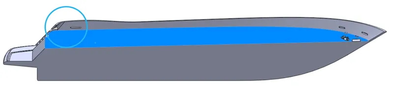
Figure 31: Surface selected for 2D sketch
- Draw a line of 1200mm such as its left end be connected to the corner and continue the sketch with spline with length of 4100 and add tangency relation between the spline and line.
- Convert the edges of the hull using convert entities and then trim the left side of converted line to make a closed 2D sketch.
- Create a extrude boss of the above sketch to the thickness of 50mm
- Select the top surface of the just extruded part and create a sketch of portholes using the Slot feature as in the blueprint. Set the slot height to 120mm and slot width to 200mm
- Add fix the slot relation to define the sketch.
- Create a boss extrude to the thickness of 20mm on the above sketch
- Create a 2D sketch on the top surface of just extruded porthole by sketching a circle of 45mm diameter on the centre of each arc edges of the porthole
- Create a boss extrude to the thickness of 60mm.
- Next, sketch a circle of 65mm diameter on each extrude of 45mm diameter circle top surface and extrude the sketch to the thickness of 10mm.
- Apply a fillet of 5mm radius on the appropriate edges of the extrude
- Create a linear pattern of the porthole by selecting one of the edges as the pattern direction and change the distance to 1200mm with instances up to 2.
- Create a fillet of 10mm radius on the required edges.
- Begin creating a new sketch on the surface selected as shown in figure
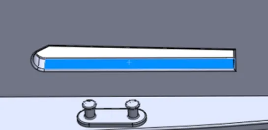
Figure 32: Surface selected for sketch
- Draw two circles of 35mm diameter of 400mm apart from each other and 37mm above the lower edge of the surface. The left-side circle be 220mm away from the left corner of the surface.
- Extrude the above sketch up to the next surface
- Begin new sketch on the surface selected as show in figure
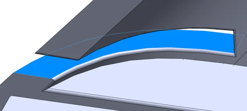
Figure 33: Surface selection
- Draw three circles of 35mm diameter with dimensions as shown in figure
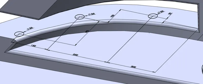
Figure 34: Sketch on the surface
- Create a boss extrude up to next surface
- Create a fillet of radius of 10mm and 5mm on the required edges and stair edges respectively
- Create a new plane using the reference geometry feature and selecting the appropriate plane ie., left side plane of the stairs and change the offset distance to 50mm
- Create a 2D sketch on the new plane by drawing a centreline on the edge of stairs surface and continue by creating a 3-point centre rectangle on the midpoint of the centreline with length of 1560mm and breadth of 190mm.
- Apply sketch fillet of 60mm radius on the upper corners of the rectangle
- Using reference geometry, create a new plane by selecting the left upper starting point of the rectangle as the first reference and selecting the left edge of the rectangle as the second reference.
- Create a sketch of circle of 30mm diameter on the new plane and using the sweep feature create a solid sweep with circle sketch as the profile and rectangle sketch as the path.
- Next, create a new sketch on the Midplane by offsetting the outer edge of the hull and change the offset distance to 335mm outwards.
- Continue the sketch with drawing the lines on the lower edge of the hull and make them perpendicular to the upper offset curve.
- The lines be 160mm apart and 650mm apart from each other as required on the blueprint.
- Again, offset the outer edge of the hull to the distance of 70mm downwards.
- Using extend entities feature, extend all the vertical lines to the lower offset.
- Using Power trim tool, trim parts of the lines to create one long chain.
- Remove all the sketch relations and dimensions
- Click and drag over the complete sketch and add fix relation to define the sketch.
- Rename the sketch as the “Railing Reference”
- Next, create another sketch on the Midplane and convert the railing of the reference sketch using convert entities.
- Create a sketch fillet of 60mm radius on the corners of the all 28 corners points of the railing
- Create a new sketch on the Plane 11 and offset the two outer edges of the hull to the offset distance of 60mm inwards.
- Create a projected curve using the above two sketches
- Using reference geometry, create a new plane by selecting the endpoint of the projected curve as the first reference and the edge connected to the particular point of the projected curve as the second reference.
- Create a sketch of circle of 60mm diameter on the new plane.
- Create a solid sweep using 2D circle sketch as the profile and railing reference curve as path.
- Create a new sketch on the Top plane with lines and sketch fillet as shown in figure
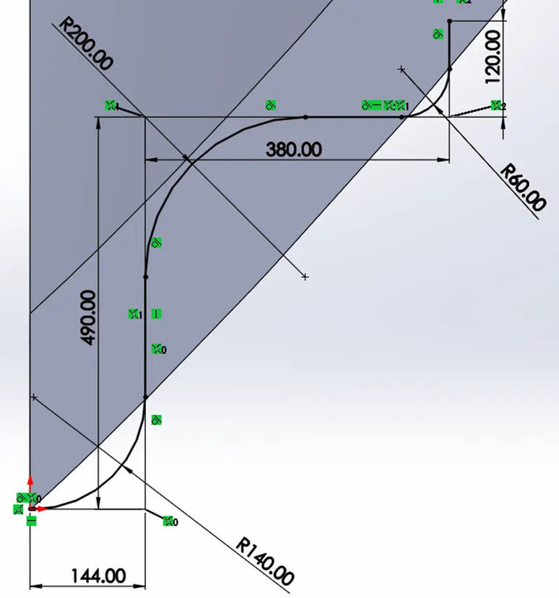
Figure 35: Sketch on the top plane
- Create a new sketch on the Midplane and draw a vertical line of 380mm and 800mm line perpendicular to it on the corner of the hull.
- Add sketch fillet of 60mm radius on the corner of the sketch.
- Create a projected curve using above two sketches on the Top plane and Midplane.
- Create a new plane using reference geometry by selecting lower endpoint of the curve as the first reference and lower edge as the second reference
- Create a circle of 60mm diameter on the new plane and add pierce relation between the circle and the curve.
- Create a solid sweep by selecting 2D circle sketch as profile and curve as the path
- Create a new sketch on the Midplane and draw a corner rectangle of 125mm breadth and 145mm length as shown in figure and horizontal and vertical distance from the corner of the hull be 100mm and 25mm respectively.
- Create a boss extrude to the thickness 100mm on the above sketch
- Create a fillet of radius of 30mm, 50mm and 10mm respectively on the appropriate edges respectively.
- Select the surface as shown in figure and begin new sketch
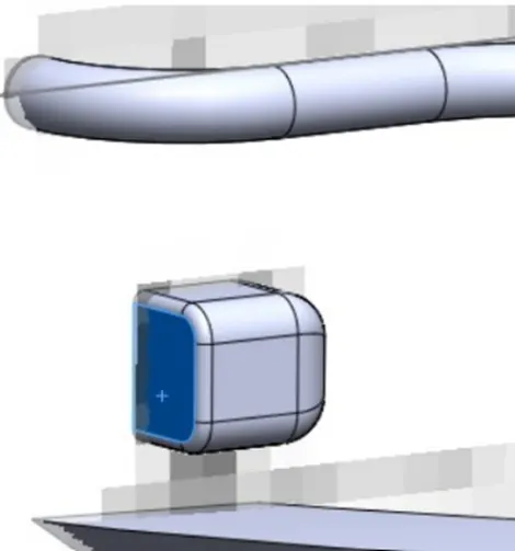
Figure 36: Surface selected for sketch
- Convert the edges of the surface using Convert entities and create an extrude cut to the depth of 5mm.
- Create a fillet of 1mm radius on the edges of the extrude cut.
- Select the surface as shown in figure to create a new sketch
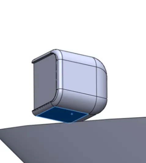
Figure 37: Surface selected for sketch
- Draw a half circle of 70mm diameter and close it with line
- Create a extrude up to hull for the above sketch.
- Create a new sketch on the Midplane and draw a centreline connected with the railing and also draw a line of 500mm length having parallel relation with the centreline.
- Draw a second centreline of 65mm perpendicular to the first centreline and connected with the midpoint of the first centreline and midpoint of the line.
- Create a new sketch on the top plane and draw a line between the same railing in which Midplane sketch was drawn
- Create a projected curve using both the above sketches
- Create a new plane using left endpoint of curve as the first reference and complete curve as the second reference
- Create an ellipse of 80mmx40mm on the newly created plane
- Create a solid sweep by selecting ellipse sketch as the profile and the projected curve as the path
- Select the front side of the ellipse and draw a horizontal line on the ellipse
- Create a new plane by selecting the sketch line as the first reference and front surface of the ellipse as the second reference using reference geometry.
- Create a new sketch on the new plane by drawing straight centreline on the top of solid sweep.
- Draw two circles of 65mm diameter on the each side of the sweep and 150mm from the corners on the both side
- Create a boss extrude up to the surface and select the surface opposite to the sweep.
- Create a fillet of radius of 8mm on the edges of the sweep
- Create a fillet of radius of 10mm and 50mm on the appropriate edges of the hull
- Select the surface as shown in figure
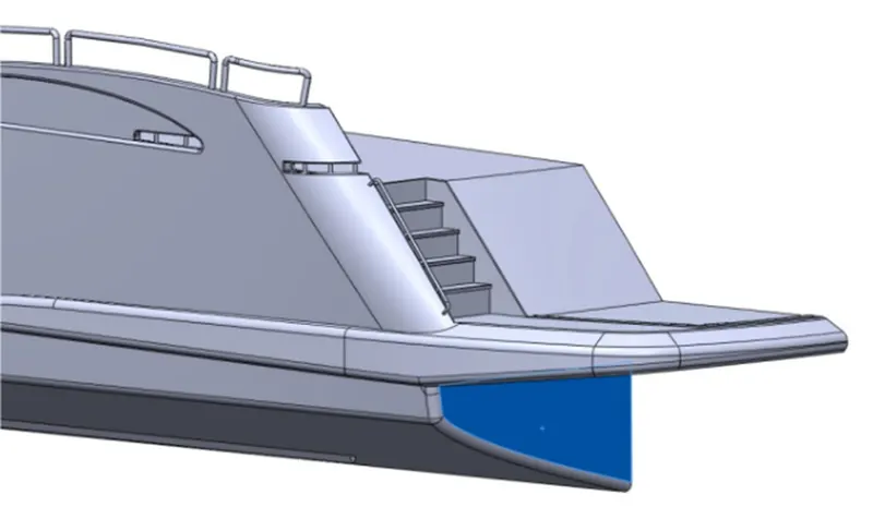
Figure 38: Surface selection for the sketch
- Create a sketch using line and centreline on the selected surface with dimension as shown in figure
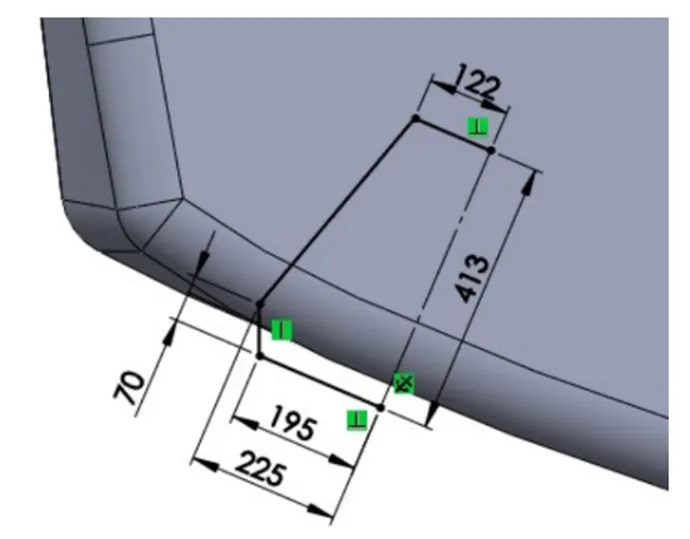
Figure 39: Sketch on the surface
- Mirror the sketch by selecting the lines as the sketch entities and selecting the centreline as Mirror about using Mirror entities feature
- Create a boss extrude to the thickness of 40mm for the above sketch.
- Select the top surface of the extrude to create a new sketch and draw the lines with dimensions as shown in figure
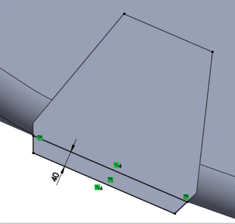
Figure 40: Sketch on the surface
- Create a boss extrude of the above sketch to the thickness of 400mm
- Apply angle distance chamfer of 90mm and 45⁰ on the edges of the extrude
- Create a fillet of 8mm radius on the edges of the extrude
- Select the surface and begin the new sketch with dimensions as shown in figure
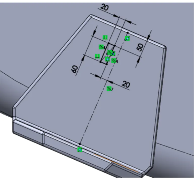
Figure 41: Sketch on the selected surface
- Mirror the rectangle about the centreline with the Mirror feature
- Create a boss extrude to the thickness of 60mm for the above sketch
- Select the surface for the new sketch as shown in figure
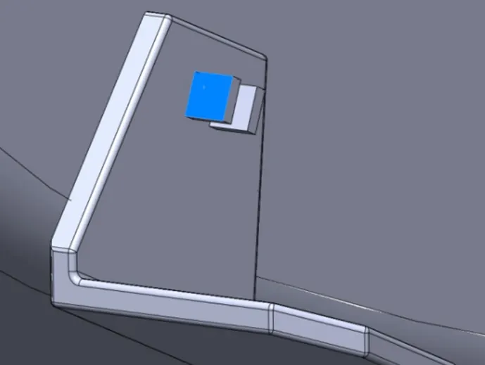
Figure 42: Surface selected for new sketch
- Draw centreline from upper left corner to the lower right corner and repeat the same with the centreline for the other corners. Sketch a circle of 25mm diameter at the coincident point of the centrelines.
- Create an extrude cut to the depth of 100mm
- Select the surface and begin the new sketch as shown in figure
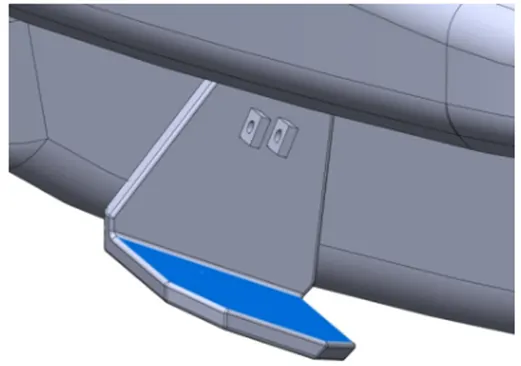
Figure 43: Surface selected for sketch
- Draw the centreline at the midpoint of the surface and draw a rectangle of 60mm length and 20mm breadth using 3-point rectangle and 30mm apart from the centreline and 50mm above the lower edge of the surface
- Create a boss extrude of the above sketch to the thickness of 60mm
- Select the surface as shown in figure to begin the new sketch
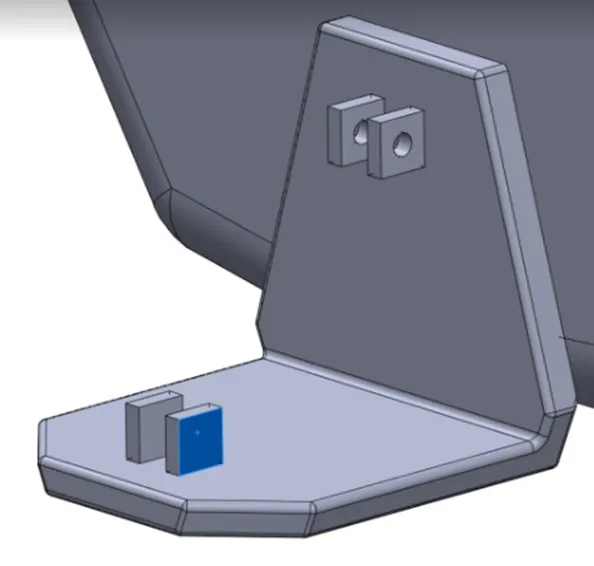
Figure 44: Surface selected for sketch
- Draw a centreline from the upper right corner to the lower left corner and then sketch a circle of 25mm diameter on the midpoint of the centreline.
- Create an extrude cut to the depth of 100mm for the above sketch
- Create a fillet of 30mm and 3mm radius on the required edges
- Apply an angle-distance chamfer of 2mm and 45⁰ on the four circular faces of the extrude cut
- Create a new plane using Reference geometry by selecting one of the faces of the extruded cut as the first reference and the face opposite to it as second reference.
- Create a new sketch on the new plane as shown in figure
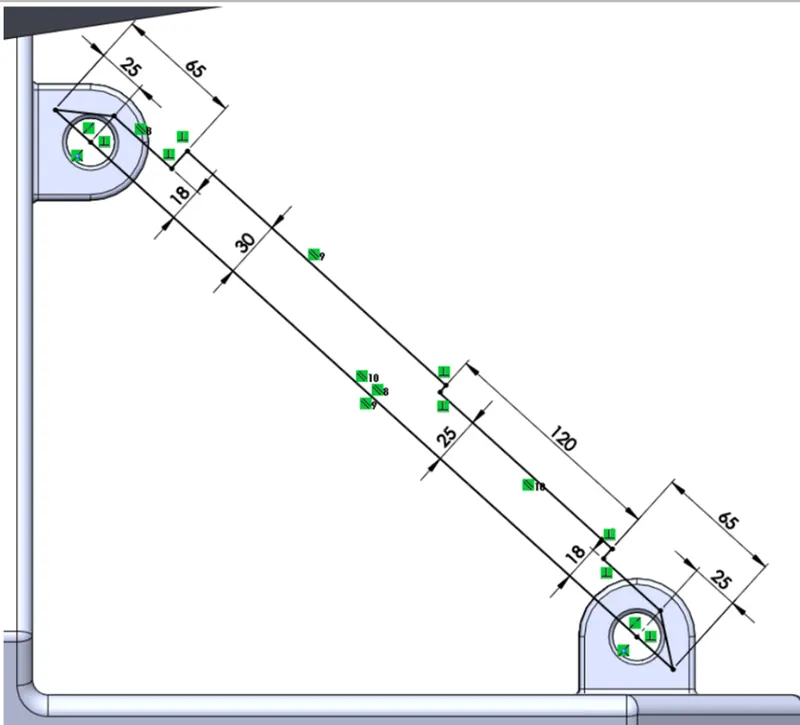
Figure 45: Sketch on the new plane
- Create a revolve by selecting the longer vertical line as the axis of revolution using Revolve feature
- Create a sketch by offsetting the both circular edges by 2mm inwards on the new plane created above
- Create a boss extrude Midplane to the thickness of 90mm.
- Apply an angle distance Chamfer of 2mm and 45⁰ on the appropriate edges
- Create a new sketch on the Midplane as shown in figure
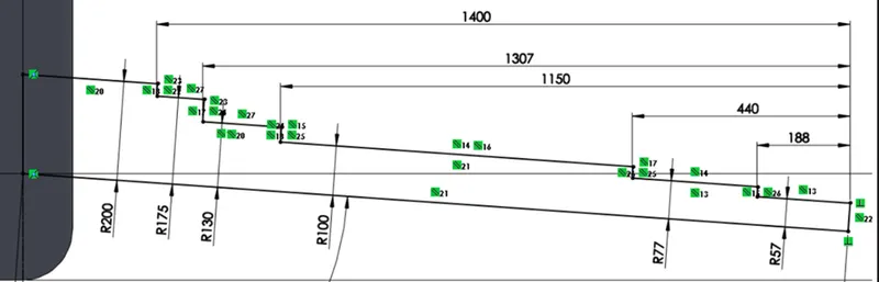
Figure 46: Sketch on the midplane
- Create a new revolve by selecting the longer vertical line as the axis of the revolution
- Apply an angle distance chamfer of 20mm and 45⁰ on the required edges of the revolve
- Apply distance-distance chamfer of 20mm and 50mm as direction1 and direction2 respectively on the required edges of the revolve
- Create a fillet of 10mm radius on the appropriate edges of the revolve
- Create a new sketch on the Midplane as shown in figure
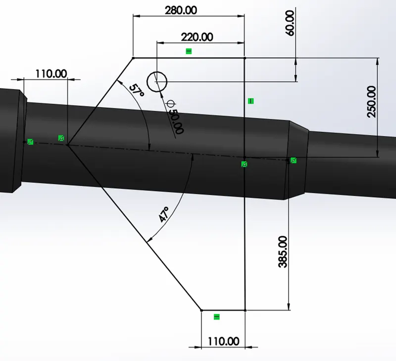
Figure 47: Sketch on the Midplane
- Create a boss extrude in Midplane direction to the thickness of 40mm
- Next, create a new sketch on the Midplane as shown in figure
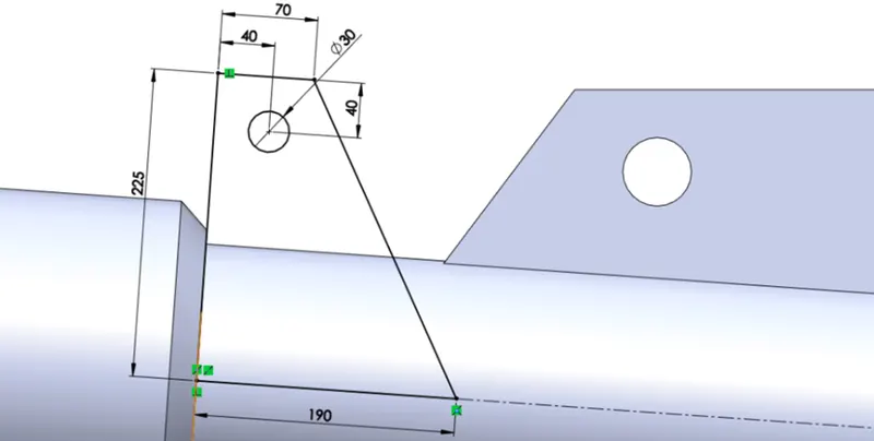
Figure 48: Sketch on the Midplane
- Create a boss extrude Midplane to the thickness of 25mm for the above sketch
- Create a new sketch on the Midplane and draw a horizontal centreline connected between the centre of the circular edge of the above extrude part and the edge of the hull.
- Then, draw a line of 800mm from the centre of the circular edge of the above extrude and 45⁰ from the centreline
- Create a thin extrude in Midplane direction to the thickness of 50mm and enable the thin feature with the direction of Midplane to the thickness of 10mm.
- Create a fillet of 100mm, 25mm and 5mm on the appropriate edges and the faces
- Next, the surface as shown in figure to create a new sketch
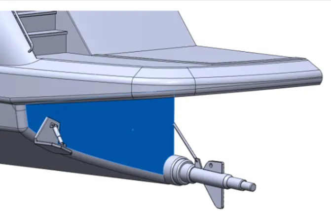
Figure 49: Surface selected for new sketch
- Sketch a line of 1000mm from the centre of the revolve at an angle of 69 from the vertical edge of the surface and rename the sketch as the “Pattern Direction”
- Create a linear pattern by selecting the pattern direction sketch and change the distance to 1600mm up to 2 instances for the complete revolve
- Create a new sketch on the front plane and draw a rectangle of 5500mm length and 500mm breadth on the left edge of the hull
- Create an extrude cut for the above sketch in through all direction
- Create a 3D sketch from the centre of the first hole to centre of the second hole as shown in figure.
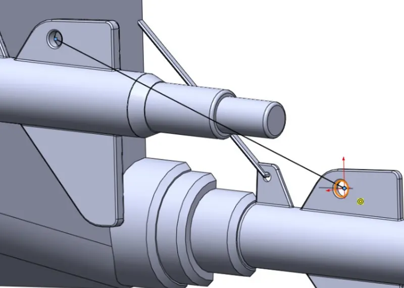
Figure 50: 3D sketch on the revolve
- Create a new reference plane using reference geometry feature by selecting the lower endpoint of line as first reference and the line as the second reference
- Create a new sketch on the new plane by drawing a circle of 40mm diameter on the circular edge of the revolve profile
- Create a boss extrude to the thickness of 1650mm for the above sketch
- Create a fillet of 20mm radius on the upper edge of the extrude
- Create a new sketch on the Midplane as shown in figure
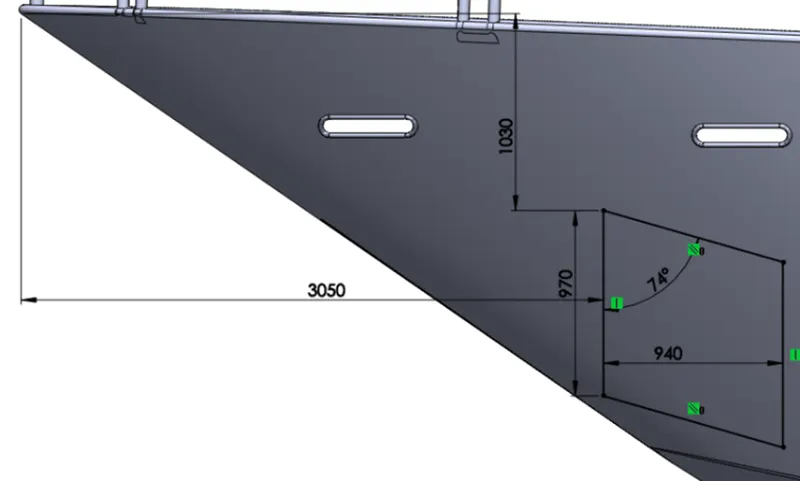
Figure 51: Sketch on the Midplane
- Create an extrude offset from the surface to the thickness of 20mm in reverse offset outwards the hull
- Create a new plane by selecting the one of the corner points of the extrude as first reference, another corner point as the second reference and third corner point as the third reference
- Create another new plane by selecting the new plane as the first reference and change the offset distance of 50mm with the direction of plane outwards.
- Create a new sketch on the newly created plane and draw a vertical centreline at its centre and sketch as shown in figure
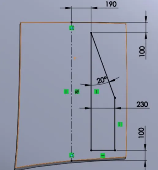
Figure 52: Sketch on the new plane
- Create a boss extrude to the thickness of 50mm of the above sketch pointed outwards.
- Apply distance-distance chamfer on the edge of the above boss extrude with direction1 and direction2 as 170mm and 40mm respectively
- Create another sketch on the new plane and sketch as shown in figure
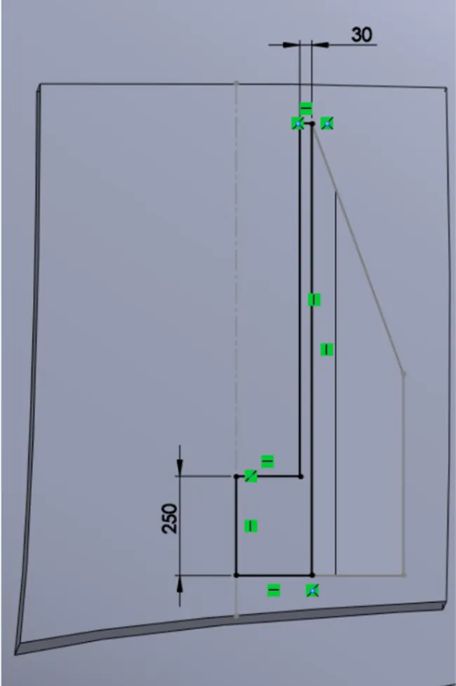
Figure 53: Sketch on the new plane
- Create a boss extrude to the thickness of 100mm outwards for the above sketch
- Create distance-distance chamfer on the edge of the above extrude with direction1 and direction2 as 960mm and 50mm respectively
- Create another sketch on the same new plane and draw a rectangle of 40mm breadth and vertical line at the left-side is collinear with the vertical line of previous boss extrude.
- Create a boss extrude of the above sketch to the thickness of 140mm outwards.
- Next, begin sketch by selecting the surface as shown in figure
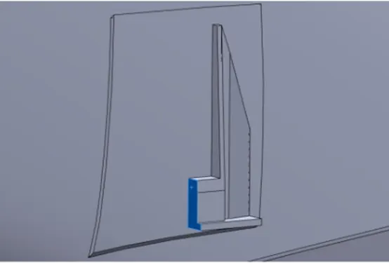
Figure 54: Surface selected for new sketch
- Create sketch on the selected surface using line and spline tools as shown in figure
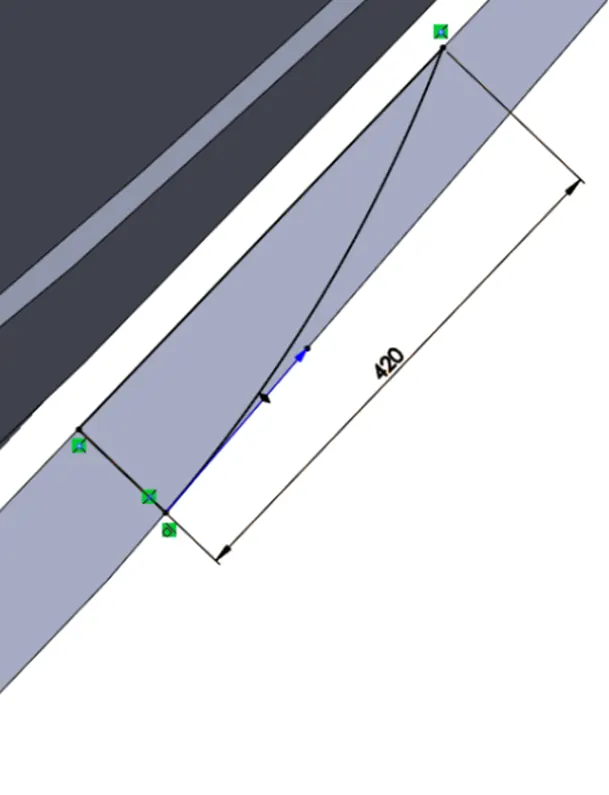
Figure 55: Sketch on the surface
- Create boss extrude to the thickness of 80mm in outward direction for the above sketch
- Create an angle-distance chamfer of 40mm and 45⁰ on the above extrude.
- Create distance-distance chamfer of 200mm and 120mm as direction1 and direction2 respectively on the appropriate edge
- Create a fillet of 10mm and 50mm on the required edges of the extrude
- Mirror the anchor by selecting the left side of the anchor as the Mirror face using Mirror feature
- Create a new sketch as shown in figure
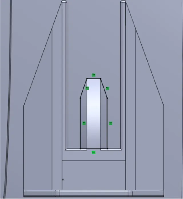
Figure 56: Sketch of the anchor
- Create an extrude for the rear side of anchor up to the hull using the above sketch
- Create a new sketch on the Midplane as shown in figure
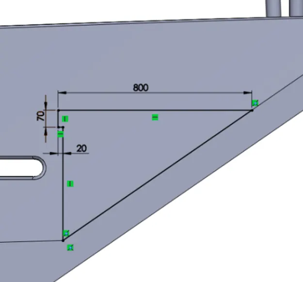
Figure 57: Sketch on the Midplane
- Create an extrude up to the hull on the above sketch
- Combine the extrude and the hull body using the Combine feature. The two bodies are now connected
- Create a new sketch on the Midplane and draw a corner rectangle of 6000mm length and 1250mm breadth
- Create an extrude cut in Midplane direction to the depth of 1800mm and enable the thin feature to 5mm
- Create a new sketch on the blue surface as shown in figure
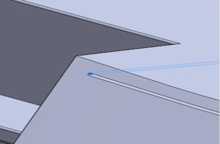
Figure 58: Surface selected for new sketch
- Begin the sketch on the selected surface and convert the sketch of the previous extruded cut using convert entities feature
- Create an extrude cut to the thickness of 5mm. The garage space is now separated solid body
- Split the garage body from the hull by using split tool and enable the Consume cut bodies feature. This body will be saved as garage door
- Create a new sketch by selecting the surface as shown in figure
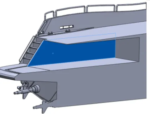
Figure 59: Surface selected for new sketch
- Draw a corner rectangle of 4500mm length and 2100mm breadth on the selected surface
- Create an extrude cut to the depth of 600mm
- Select the blue surface as shown in figure
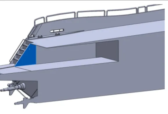
Figure 60: Surface selected for the new sketch
- Draw a circle of 50mm diameter at horizontal and vertical distance of 20mm and 50mm from the corner
- Create a boss extrude to the thickness of 150mm for the above sketch
- Create a new sketch on the Midplane and draw a spline without any midpoint as shown in blueprint and the fix relation on the spline to define the spline.
- Offset the spline using Offset entities feature to the offset distance of 120mm and again offset the spline to 200mm
- Draw a straight line without any midpoint as shown in blueprint and add fix relation to define the line.
- Select the previous sketch and the faces as Face to split to create split lines on the Hull
- Change the entire body appearance to white colour
- Select all the faces of the window and change their appearance to black
- Next, select the face of the blue strips and change its appearance to dark blue
- Change the colour of the window edges to dark blue
- Change the colour of propeller shaft and colour of Floodlight to dark grey
- Change the colour of front face of the floodlight to white
- Change the colour of the anchor and the railing to light grey
- The appearance of edges of anchor hole and porthole edges be changed to light grey
- Select the Deck surface and apply surface offset feature and change the offset distance to 0mm to copy the deck surface.
- Rename the surface offset to “Deck Surface”.
- Mirror the hull by selecting the Midplane as the Mirror face and select the hull main body as bodies to mirror
- Change the colour of the stabiliser as light grey
- Mirror the stabiliser by choosing the Midplane as the Mirror face and select the stabiliser as the Bodies to mirror
- Enable PhotoView 360 feature and edit the decal of the deck surface and browse the “Main floor” decal. In Mapping tab, enable fit width to the selection & fit height to the selection options.
- Enable "Main floor” decal on the garage deck surface with change of width to 5500mm to match the width of the deck decal and select Fit height to selection option.
- Enable “Main floor” decal on the rear deck surface to project the decal with change of width to 5500mm to match the width of the deck decal and select Fit height to selection option
- Follow same procedure for the other rear deck surface
- Enable “Stair step” decal on the one of the stairstep surfaces to project the decal along with it select Fixed aspect ratio, Fit width to selection & Fit height to selection options.
- Repeat this for all other steps
- Change the colour of the stair step fronts to a custom light brown by changing the RGB numbers to 190,169 and 146.
- Enable “Hatch Front” decal on the hatch surface.
- Enable “Main floor” decal on the front deck surface along with it change the width to 5500mm to match the width of the deck decal and select the fit height to selection option.
- Finally, save the file
5. Garage Door
A garage door is a large door on a garage that opens either manually or by an electric motor (a garage door opener). Garage door are frequently large enough to accommodate automobiles or other vehicles. The operating mechanism is spring-loaded or counterbalanced to the offset the weight of the door or reduce human or motor effort required to open the door. Least commonly, some garage door slide or swing horizontally. Doors are made of wood, metal, or fibreglass, and may be insulated to prevent heat loss.
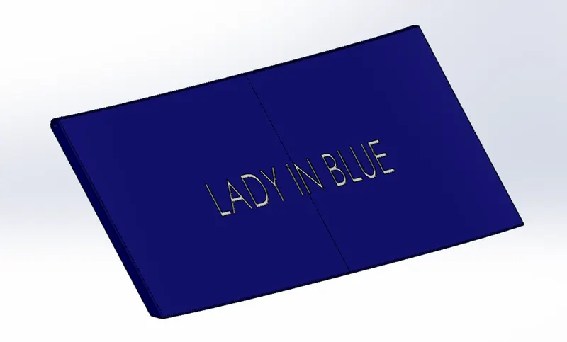
Figure 61: Garage Door
Commands:
- Line
- Spline
- Circle
- Text
- Extrude cut
- Reference Plane
- Fillet
- Shell
- Mirror
Procedure:
- Open the exported body of the Hull as main body: Garage_Door
- Select the surface as shown in figure to begin new sketch
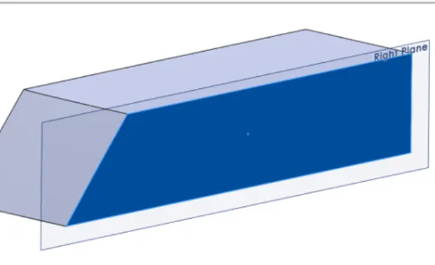
Figure 62: Surface selected for sketch
- Draw a line of 4750mm on the upper edge of the surface and line of 5800mm on the lower edge of the surface. Close the sketch using straight lines on the both sides.
- Create a extrude cut in through all direction on the above sketch
- Create a shell feature to the thickness of 100mm on the appropriate feature.
- Create a fillet of 100mm radius on the corner edge of the shell.
- Create a fillet of 15mm on the outer and inner edges of the shell
- Sketch a circle of 50mm diameter with proper dimensions on the selected surface as shown in figure
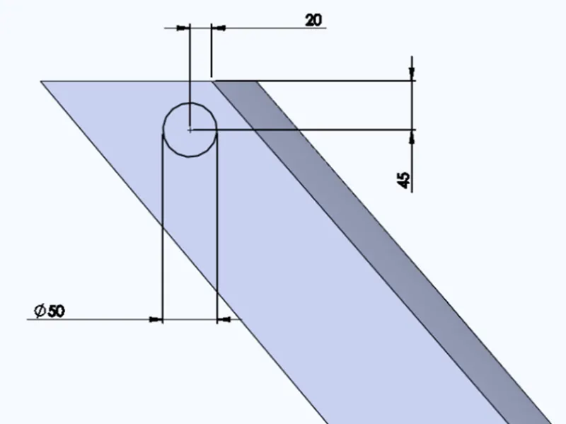
Figure 63: Sketch on the selected surface
- Create an extrude cut for the above sketch to the depth of 100mm.
- Create a fillet of 10mm, 15mm and 50mm radius on the appropriate edges.
- Mirror the garage door by selecting the right plane as the Mirror face and entire body of the garage as Bodies to Mirror.
- Create a new plane using Reference plane geometry feature by selecting Front plane as the first reference with the offset distance of 31000mm.
- Create a new 2D sketch on the new plane by drawing a horizontal centreline of 2500mm such that its left end is 1250mm away from the Right plane and 500mm above the lower edge of the garage door.
- Create the name of the yacht using Text feature by selecting the centreline as the reference curve and change the font to Century Gothic with Text height to 200mm
- Create an extrude cut offset from the surface to the depth of 8mm by selecting the appropriate face. Use reverse offset option to make sure the extrude cut is directed inwards the body.
- Change the colour of the garage door body by changing the colour to custom dark blue by changing the RGB numbers to 0,0,128.
- Change the colour of the yacht name to white.
- Finally, save the file.
6. Front Seat
Front seat feature two connected seats that are built back to back from one and other. They have a built-in storage underneath them. Lounge seats can also fully recline right back to make it easier for you to kick your feet up and get more comfortable. The front seat in our model was placed before the superstructure and also it has sun pads to rest on it. Sun pads are great way to reclaim lost space on our boat.
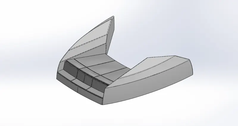
Figure 64: Front seat
Commands:
- Sketch picture
- Line
- Spline
- Circle
- Arcs
- Extruded surface
- Lofted surface
- Trim surface
- Filled surface
- Knit surface
- Swept surface
- Revolved surface
- Extruded cut
- Revolved Boss/Base
- Chamfer
- Fillet
- Mirror
- Dome
Procedure:
- Open the Blueprint setup file and then save as the file as Front Seat
- Import the deck surface of the hull as the interface surface using insert part feature.
- Select the deck surface of the hull and begin the new sketch.
- Draw the spline as shown in blueprint on the arc edge of the frontseat. Pull the arrow point of the left endpoint of the spline to match the curve of the blueprint.
- Add dimension to the sketch as shown in figure
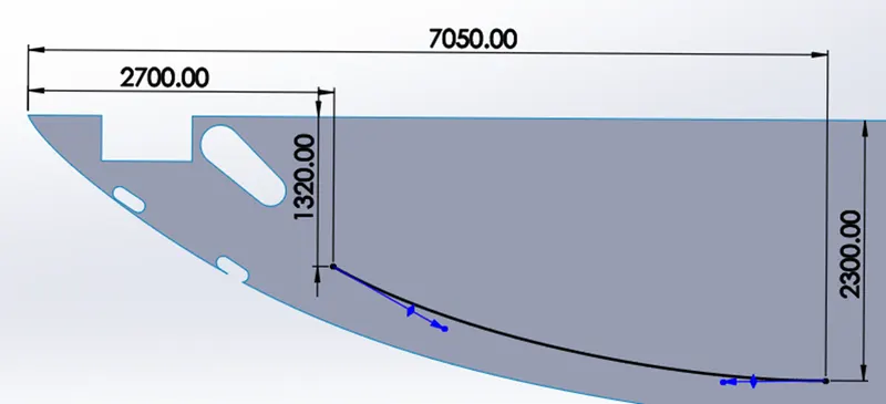
Figure 65: Sketch on the deck surface of the Hull
- Create a new plane using Reference geometry feature by selecting the Spline as the first reference and right endpoint of the spline as the second reference.
- Create a new sketch on the new plane and draw a spline of 1000mm and 160mm vertical distance connected to the previous spline. Add vertical relation on the arrow point of the lower spline endpoint.
- Create a surface sweep by selecting the above spline sketch as the profile and the 1st spline sketch as the path.
- Select again the deck surface of the hull for new sketch and switch to top view.
- Draw two connected lines such that left endpoint of the line has pierce relation with the left lower corner of the surface sweep and right endpoint of another line has same relation with lower right corner of the surface sweep.
- Add horizontal and vertical dimension of 5240mm and 993mm at the connecting point of the both of the line.
- Create a surface extrude up to vertex and selecting the upper edge of the surface sweep as Vertex.
- Using Trim surface feature, remove the unwanted surfaces
- Create a surface fill selecting the upper edges of the hole as the patch boundaries.
- Create a new sketch on the upper new created surface and switch to Top view. Draw a spline with dimensions as shown in figure
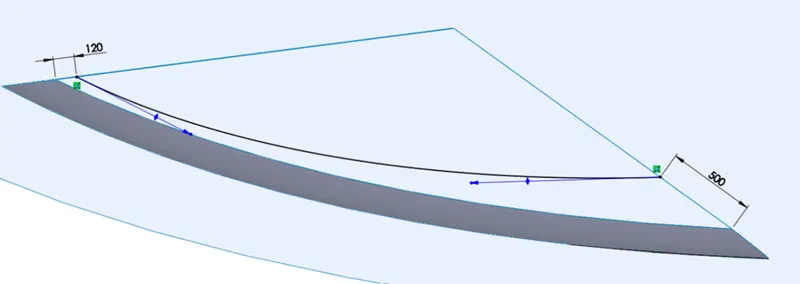
Figure 66: Sketch on the upper surface
- Trim the unwanted surface by selecting the above sketch as Trim tool using Trim surface feature
- Create a new sketch on the Midplane and draw a straight line having parallel relation with the upper edge of the surface sweep and 250mm below it.
- Apply Trim surface feature by selecting the above sketch as the Trim tool and remove the unwanted surfaces
- Create a surface loft by selecting the appropriate edges as the loft profiles.
- Using Trim surface feature, selecting the surface of the loft as trim tool remove the unwanted surfaces
- Knit all the surfaces of the Front seat using surface knit feature.
- Fill the underside of the body by selecting the three edges of underside of body using Surface fill tool.
- Knit the above surface fill and the previous surface knit using Surface knit feature.
- Apply distance-distance chamfer of 200mm and 250mm as direction1 and direction2 respectively on the required edges of the front seat
- Create a new sketch on the right surface of the Front seat as shown in figure
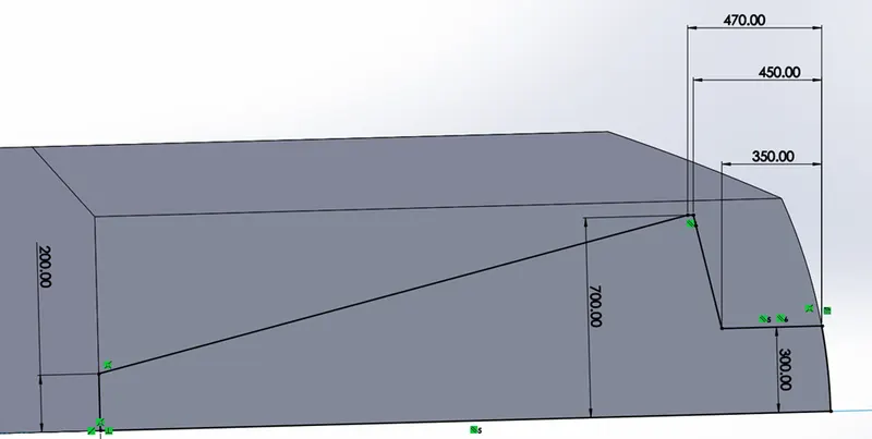
Figure 67: Sketch on the Surface
- Convert the right-side curve using convert entities feature
- Trim the upper part of the curve using Power Trim tool
- Draw a centre line of 8450mm from the left lower corner and continue by drawing another centreline of 2000mm perpendicular to the previous centreline.
- Create a revolve by selecting the 2000mm centreline as the axis of revolution and change the direction angle to 10⁰
- Create a new sketch on the Top plane by drawing a corner rectangle of 3500mm length and 1000mm breadth such that the lower horizontal line is connected to the Midplane and the left vertical line be 500mm away from the left corner.
- Create an extrude cut to the depth of 6000mm such that the offset is directed downwards.
- Select the surface as shown in figure to begin new sketch
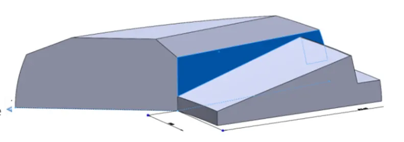
Figure 68: Surface selected for new sketch
- Offset the revolved surface edge to 5mm distance upwards using Offset entities feature.
- Offset again the same edge to the distance of 45mm and draw the lines to close both offset lines.
- Draw two diagonal lines with the dimensions as shown in figure and trim the line between the diagonal lines
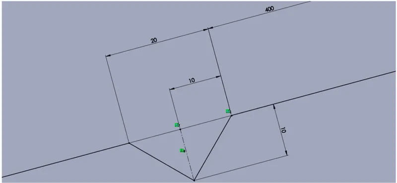
Figure 69: Sketch of the diagonal lines
- Offset other two edges of the revolve connected to the front seat surface to the offset distance of 5mm.
- Again, offset those edges to 45mm distance and draw the lines at the ends of both the offset to close the sketch.
- Draw a centreline of 8450mm from the lower corner of the surface and then draw a vertical centreline of 2000mm perpendicular to previous centreline.
- Create a revolve for the above sketch using 2000mm centreline as the axis of revolution and change the direction angle to 10⁰
- Selecting the previous sketch used for the extrude cut to the depth of 6000mm and its offset directed downwards.
- Select the surface as shown in figure to create a new sketch.
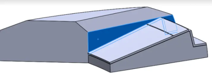
Figure 70: Surface selected for new sketch
- Draw a corner rectangle of 4400mm length and 1200mm breadth such that the left lower corner of the rectangle is connected to the lower corner of body.
- Create an extrude cut to the depth of 5mm directed outwards as shown in figure.
- Apply angle distance chamfer of 60mm and 45⁰ on the appropriate edge of the front seat
- Create a new sketch on the Top plane by sketching a straight line such that the ends of the line are connected with the edges of the matrasses and 440mm and 340mm distance between the left endpoint of the line and edge and right endpoint of line and edge respectively.
- Create an extrude cut enabling thin feature option with thickness of 2.5mm in direction as up to the body and selecting the Front seat knitted body as the reference.
- Apply a fillet of 10mm and 30mm radius on the appropriate edges of the front seat.
- Mirror the centre body of the Front seat by selecting the free face of the front seat as the Mirror face and Centre body of the front seat as Bodies to Mirror.
- Mirror the side body of the Front seat by selecting the Midplane as the Mirror face.
- Mirror the two middle mattrasses of the front seat by selecting the Middle face of the Front seat as the Mirror Face.
- Mirror the other mattrasses of the front seat by selecting the Midplane as the Mirror face.
- Create a dome on the upper surface of the mattrasses to the dome distance of 30mm directed upwards.
- Create a fillet of 10mm radius on the edges of the mattrasses.
- Change the colour of the main bodies of the front seat to white colour.
- Change the colour of the mattrasses bodies to light grey.
- Finally, save the file.
7. Middle Seat
The Middle Seat in the model is placed just behind the superstructure. It is provided with a luxury table to dine out. It can also be used to have casual meeting with the co-passengers.
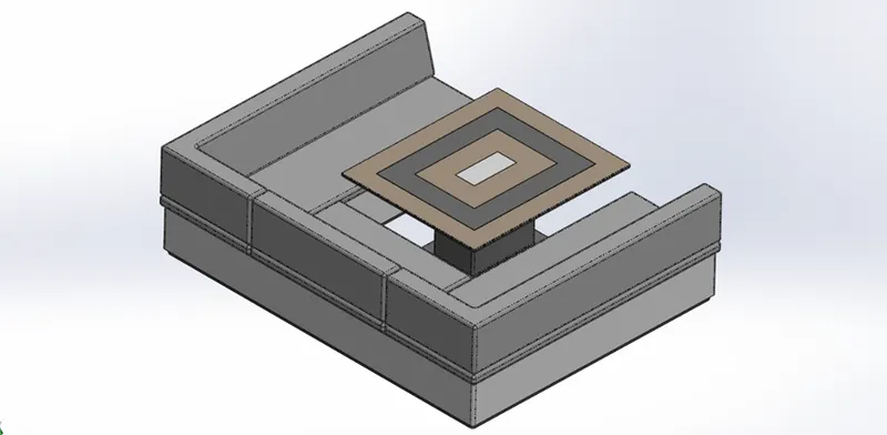
Figure 71: Middle Seat
Commands:
- Sketch Picture
- Line
- Rectangle
- Extruded Boss/Base
- Chamfer
- Fillet
- Mirror
- Reference Plane
Procedure:
- Open the Blueprint setup file and then save as the file as Middle Seat.
- Import the deck surface of the hull as interface surface using Insert part feature.
- Select the deck surface of the hull to begin the new sketch
- Switch to Top view and Sketch the following figure with dimensions as shown in figure
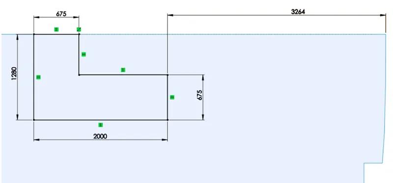
Figure 72: Sketch on the Deck surface
- Create an extrude for the above sketch to the thickness of 35mm in upwards direction
- Select the upper surface of the extruded part to create a new sketch
- Offset the edges of the surface to 20mm outwards.
- Trim the upper part of the offset lines and draw the horizontal line on the upper edge to create a closed sketch.
- Create an extrude for the above sketch of 300mm depth directed upwards.
- Create a new plane using Reference plane geometry by selecting the upper surface of the extrude as the first reference and offset it to a distance of 5mm.
- Next, create a new sketch on the new plane similar to the previous sketch with dimensions as shown in figure
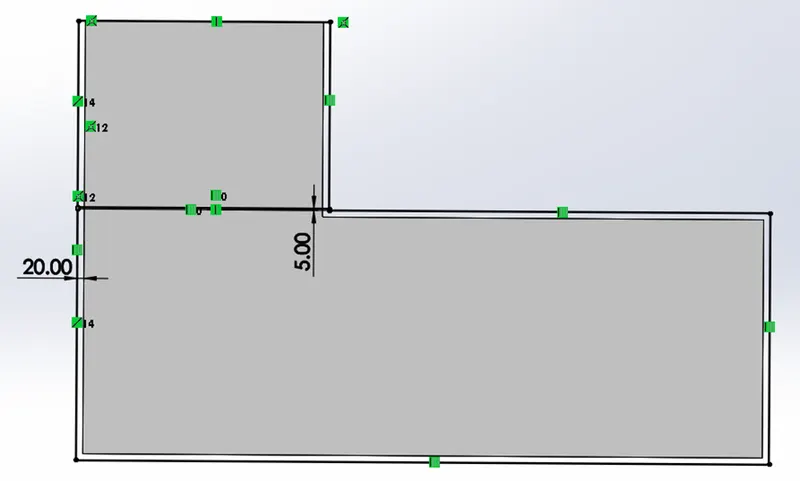
Figure 73: Sketch on the new plane
- Create an Extruded boss for the above sketch to the depth of 70mm directed upwards.
- Create a new plane using reference plane geometry by selecting the upper surface and change the offset distance to 5mm.
- Create a new 2D sketch on the new plane with dimensions as shown in figure
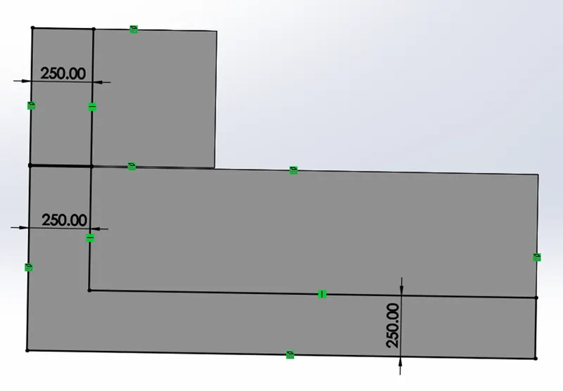
Figure 74: Sketch on the new plane
- Create an extrude for the above sketch to the depth of 350mm directed upwards.
- Create a distance-distance chamfer of 350mm and 100mm as direction1 and direction2 respectively on the required edges.
- Create a fillet of 20mm radius on the edges of the mattrasses.
- Mirror the two main bodies of the Middle seat by selecting the appropriate face as the mirror face.
- Mirror the two remaining bodies of Middle seat by selecting Midplane as the Mirror face.
- Create a fillet of 20mm radius on the required edges of the Middle seat.
- Select the imported deck surface of the hull to create a new sketch and draw a corner rectangle as shown in figure.
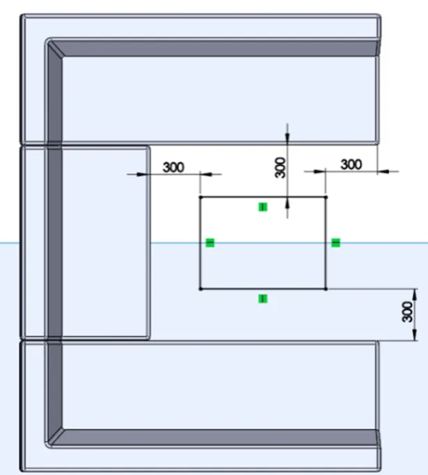
Figure 75: Sketch of table on the deck surface
- Create an extrude of the above sketch to the depth of 20mm directed upwards.
- Select the upper surface of the above extrude and create a new sketch by offsetting the edges of the surface to 100mm inwards.
- Create an extrude for the above sketch to the depth of 550mm directed upwards.
- Select the top surface of the above extrude to create a new sketch by offsetting the edged of the surface to 395mm outwards.
- Apply boss extrude feature on the above sketch to the depth of 20mm directed upwards.
- Next, select the top surface of the extrude and create a new sketch by offsetting the edges of the surface to 150mm,310mm and 480mm inwards.
- Create an extrude cut to the depth of 0.5mm on the selected sketch contours.
- Create a fillet of 15mm radius on the edges of the table stand
- Create another fillet of 5mm radius on the edges of the table.
- Change the colour of the Middle seat body to white colour and change the colour of the pillows to light grey.
- Change the colour of the table to custom grey by changing the RGB numbers to 120, 120, 120.
- Change the colour of the table top by using face option to a custom light brown by changing the RGB numbers to 190, 169, 146 and selected face to white colour.
- Finally, save the file.
8. Rear Seat
The Rear seat was placed at the end of the deck surface. The rear seat consists of locker racks and steel doors for our stairs. The flag was placed behind the rear seat since it’s the end part of the yacht. To have a new view from the yacht, it is also provided with slots to rest the glass or mug.
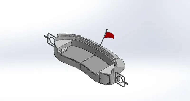
Figure 76: Rear Seat
Commands:
- Sketch Picture
- Line
- Spline
- Circle
- Arcs
- Rectangle
- Swept surface
- Extruded surface
- Offset surface
- Filled surface
- Knit surface
- Ruled surface
- Lofted surface
- Reference plane
- Extruded Boss/Base
- Revolved Boss/Base
- Fillet
- Mirror
Procedure:
- Open the Blueprint setup file and save as the file renaming it as Rear seat.
- Import the deck surface of the hull as interface surface using insert part feature.
- Create a new sketch on the Midplane using lines and splines with dimensions as shown in figure.
Figure 77: Sketch on the Midplane
- Create a new plane using reference geometry by selecting the deck surface as the first reference and appropriate point of the sketch as the second reference.
- Create a sketch on the new plane by drawing a spline such that the left endpoint of the spline is connected to the previous sketch point. Add horizontal relation on the right endpoint of the spline and add dimensions as shown in figure
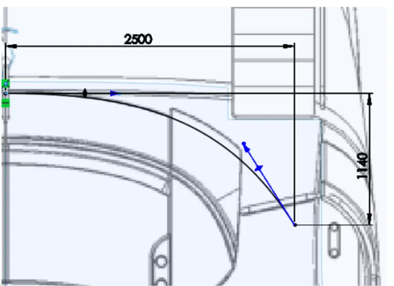
Figure 78: Sketch on the new plane
- Create a surface sweep by selecting the 1st sketch as the profile and 2nd sketch as the path.
- Create a surface offset on the selected surface as shown in figure to the offset distance of 50mm directed upwards.
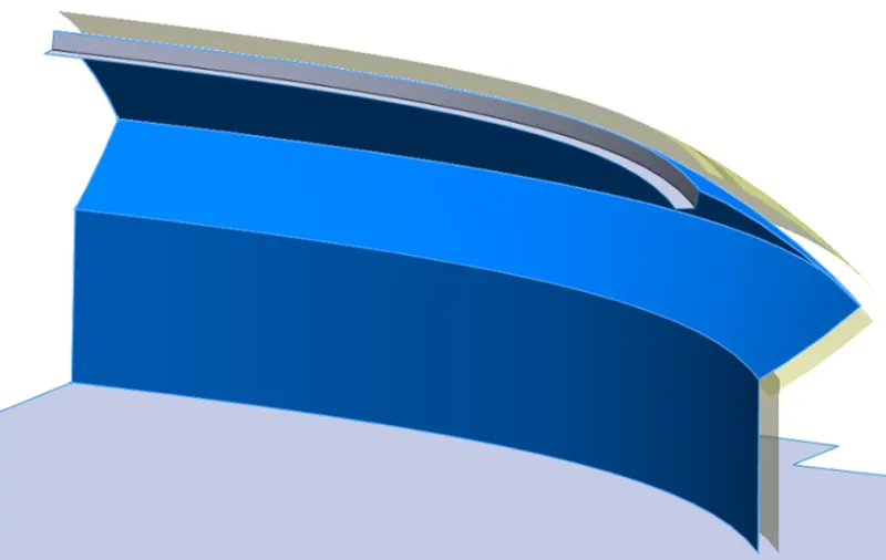
Figure 79: Surfaces selected for surface offset
- Select the plane1 to create a new sketch by drawing a vertical line of 1000mm and 1430mm and 100mm horizontally and vertically away from the upper corner of the rear seat.
- Using the power trim tool, remove the unwanted surface by selecting the previous sketch as the sketch tool.
- Create a ruled surface on the appropriate edge tangent to the surface to 150mm.
- Knit the surfaces using surface knit feature.
- Create a 2D sketch on the plane1 by drawing a spline with dimensions as shown in figure
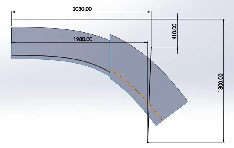
Figure 80: Sketch on the Plane1
- Trim the unwanted surface using above sketch as the trim tool by Power trim feature.
- Create a new plane on the edge of the rear seat as shown in figure
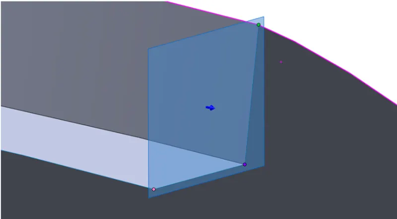
Figure 81: References selected for new plane
- Create a sketch on the newly created plane by converting the two edges using convert entities.
- Create another new plane on the edge and selecting the references as shown in figure.
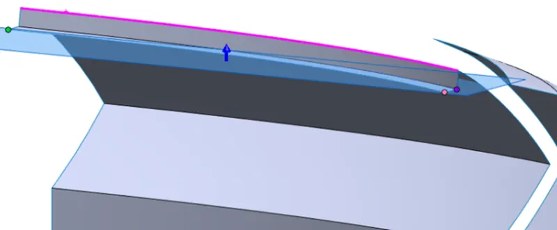
Figure 82: References selected for creating new plane
- Next, create a new sketch on the new plane by drawing a spline such that having tangency relation with the appropriate edge with dimensions as shown in figure
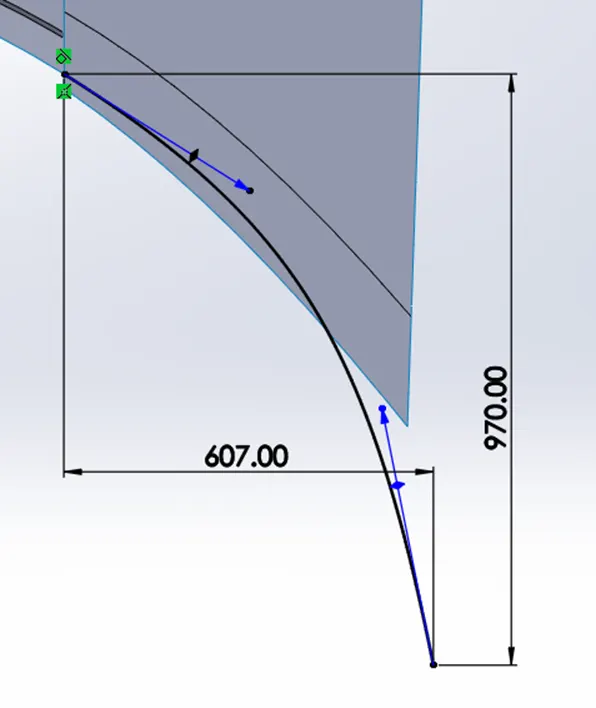
Figure 83: Sketch of spline on new plane
- Create a surface sweep using above spline sketch as the path and the other sketch as the profile.
- Extend the surface of the surface sweep2 by selecting the appropriate edge to 200mm distance.
- Using Power trim tool remove the unwanted surfaces.
- Knit the trimmed surfaces to the body using surface knit option.
- Select the deck surface to create a new sketch by converting the right edges of the rear seat by convert entities.
- Create a surface extrude for the above sketch to the distance of 1200mm directed upwards.
- Using Power trim tool to remove the unwanted surfaces.
- Knit the two surfaces using surface knit option.
- Create a 3D sketch by selecting the edges and converting the using convert entities as shown in figure
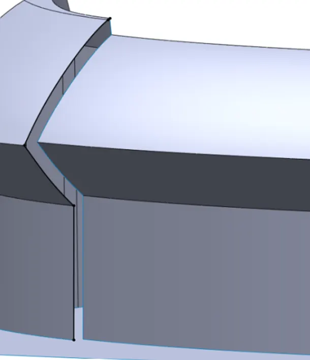
Figure 84: Edges selected in 3D Sketch
- Create another 3D sketch and converting the edges using convert entities feature as shown in figure
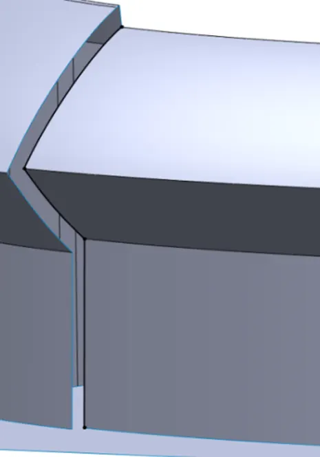
Figure 85: Edges selected for 3D sketch
- Create a surface loft by selecting the both above 3D sketches as profiles of the loft and select the appropriate edge as the guide curve with guide curve influence as to next guide.
- Knit all the three surfaces using surface knit option.
- Create a new sketch by selecting the deck surface and converting the edges using the convert entities as shown in figure
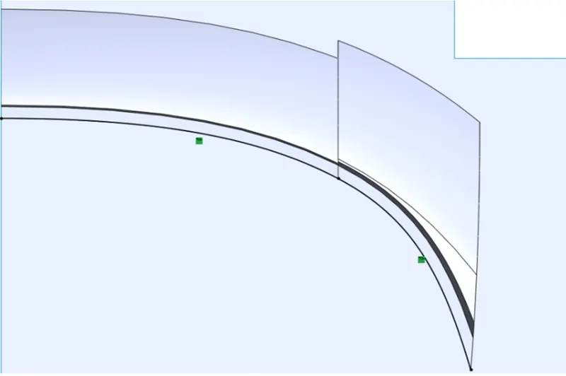
Figure 86: Edges converted on the deck surface
- Create a surface extrude for the above sketch up to surface by selecting the knitted surface of the rear seat as extrusion surface.
- Create a 3D sketch by selecting the three edges and converting them using convert entities as shown in figure
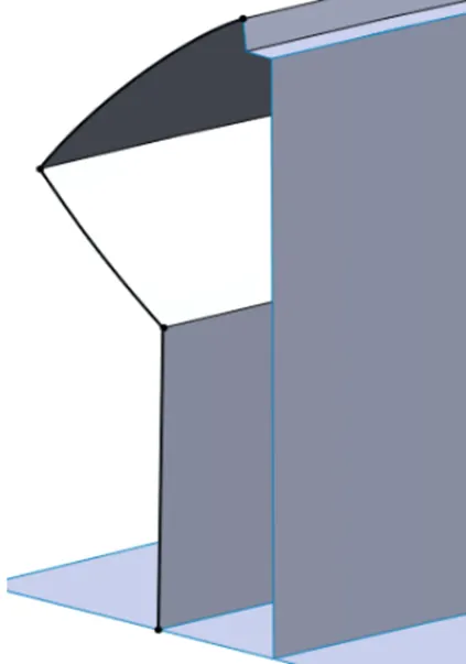
Figure 87: 3D sketch of the edges
- Create another 3D sketch on the edges as shown in figure
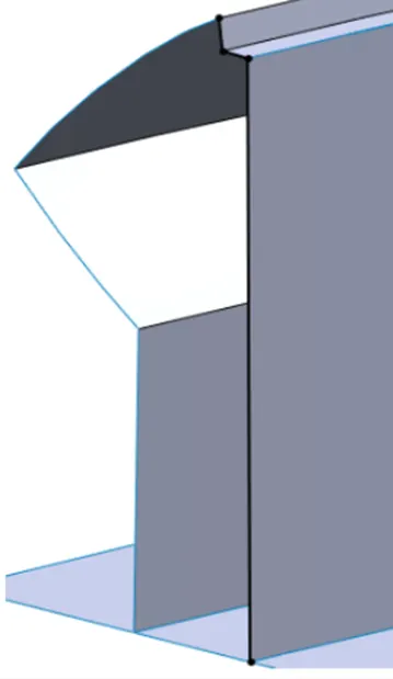
Figure 88: 3D sketch of the edge
- Create a surface loft by selecting both the above 3D sketches as the loft profiles.
- Knit all the three surfaces using surface knit option.
- Create a Surface loft on the left underside of the rear seat and then knit all the surfaces using Surface knit option.
- Create a 3D sketch by converting the right-side edge of the underside of the rear seat.
- Create a surface loft selecting the two opposite edges as loft profiles and the above 3D sketch as the guide curve.
- Extend the surface of the above surface loft to 50mm using Surface extend feature.
- Extend the surface of the surface extend1 to 20mm using Surface extend feature.
- Trim the unwanted surface using Power trim tool.
- Knit all the surfaces of the rear seat and create a solid.
- Create a 2D sketch on the deck surface by converting the edges as shown in figure
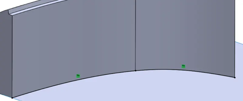
Figure 89: Edges converted on the deck surface
- Switch to top view and draw a line and spline such that the left endpoint of the spline has horizontal relation with the dimensions as shown in figure
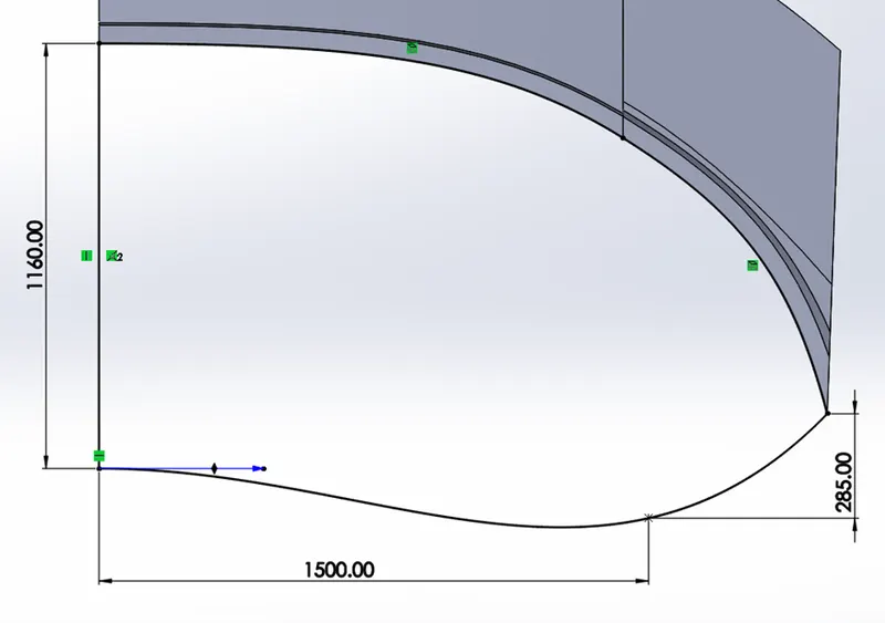
Figure 90: Sketch on the deck surface
- Create a boss extrude to the depth of 350mm for the above sketch directed upwards.
- Create a new sketch on the upper surface of the extrude and convert the edges as shown in figure
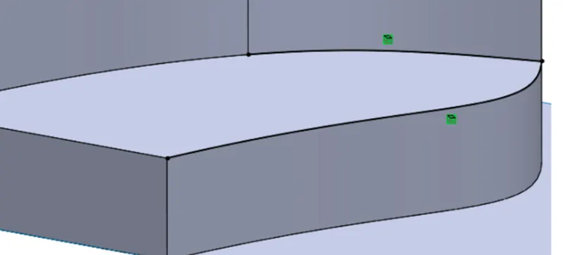
Figure 91: Edge converted on the extruded surface
- Draw a vertical line connecting the edges and using the power trim tool trim the left-side part of the sketch as shown in figure
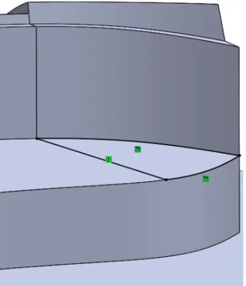
Figure 92: Final sketch
- Create an extruded Boss/Base to the thickness of 310mm for the above sketch directed upwards.
- Create a new sketch on the front plane by drawing a corner rectangle of 465mm x 585mm with dimensions as shown in figure
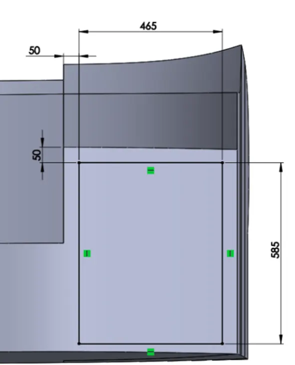
Figure 93: Sketch on the front plane
- Offset the rectangle to 5mm inwards using the Offset entities feature
- Create an extrude cut offset from the surface by selecting the face on sketch lies and offset distance be 50mm directed inwards.
- Select the top surface of the extrude and create a new sketch by converting the edge with lines and spline along with dimensions as shown in figure
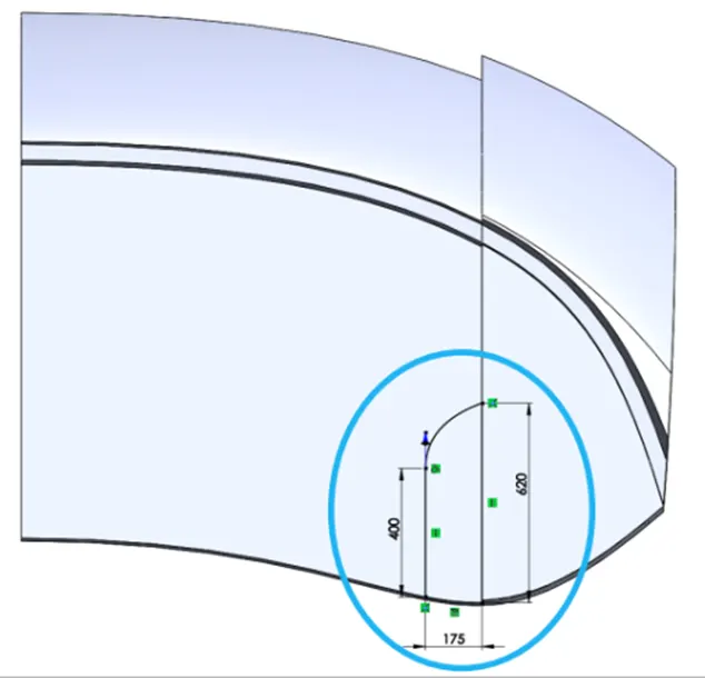
Figure 94: Sketch on the surface
- Create a boss extrude to the thickness of 120mm directed upwards for the above sketch.
- Create sketch of circles with dimensions on the above extrude as shown in figure
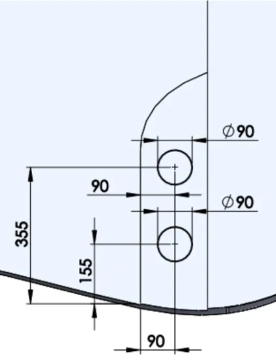
Figure 95: Sketch of circles on the extrude
- Create an extrude cut to the depth of 90mm for the above sketch.
- Create an angle distance chamfer of 7mm and 45⁰ on the edges of the glass slots.
- Create a new plane using reference geometry feature by selecting the Back plane as the first reference and the appropriate edge as the second reference.
- Create a new sketch on the plane by circle and corner rectangle with dimension as shown in figure
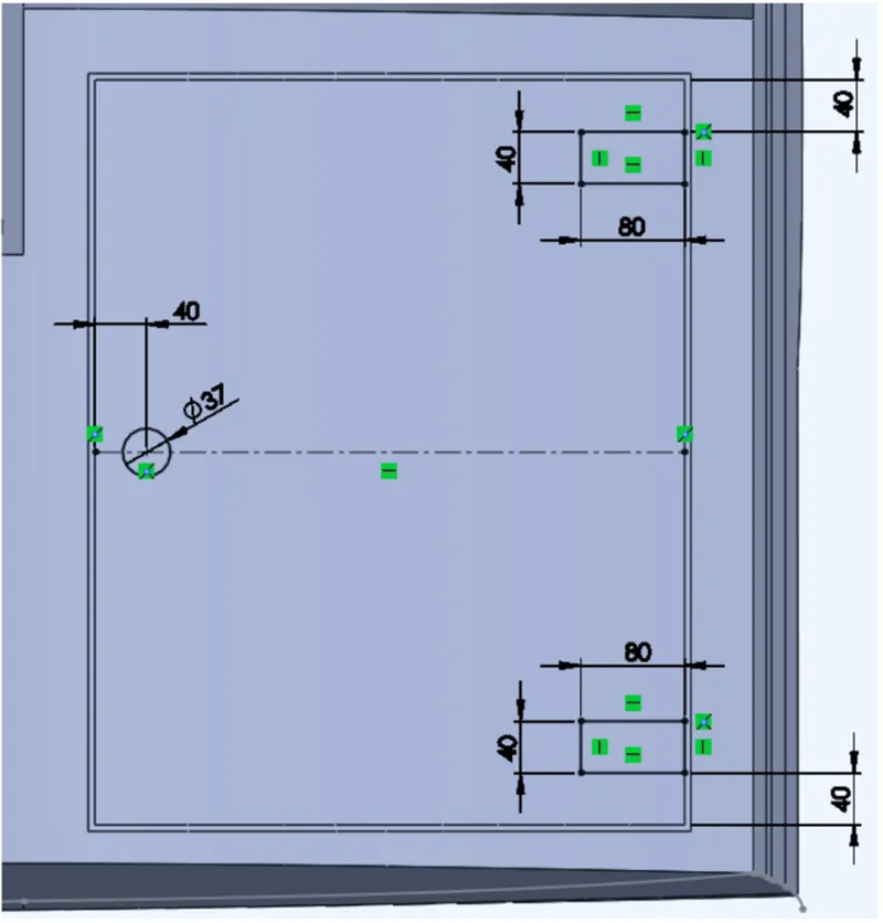
Figure 96: Sketch on the new plane
- Create an extrude offset from the surface to the thickness of 5mm directed outwards.
- Create a surface offset on the selected surface to the offset distance of 5mm directed upwards as shown in figure
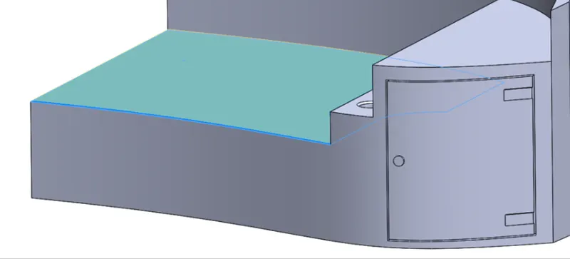
Figure 97: Surface offset
- Create a new 2D sketch on the new created surface by offsetting the surface to 2.5mm inwards.
- Trim the edges of the surface offset by selecting the above sketch as the trim tool.
- Create a new sketch by converting the entities on the surface as shown in figure
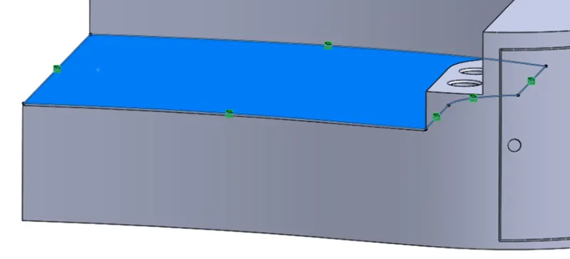
Figure 98: Sketch on the surface
- Create an extruded boss/base for the above sketch to the thickness of 60mm directed upwards
- Create a surface offset on the extruded surface to the offset distance of 5mm directed upwards.
- Select the offset surface and create a 2D sketch by offsetting particular edge to the distance of 170mm directed inwards and then using extend entities feature extend the right endpoint of the offset to the right.
- Trim the surface using above sketch as the trim tool and select the keep selections option.
- Select the surface as shown in figure to create 2D sketch
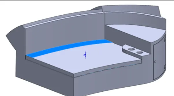
Figure 99: Surface selected for new sketch
- Convert the edges of the surface using convert entities option.
- Create an extruded Boss/Base for the above sketch to the thickness of 30mm directed upwards.
- Create a distance-distance chamfer of 307mm and 110mm as direction1 and direction2 respectively on the appropriate edge.
- Create a fillet of 10mm and 15mm on the appropriate edges of the mattrasses and the rear seat.
- Also, create a face fillet of 10mm radius by selecting the appropriate faces
- Create a fillet of 5mm,10mm &15mm radius on the outer edges of the rear seat
- Create a fillet of 3mm radius on the circular edges of the glass slots.
- Select the plane4 and create a corner rectangle of 175mm length and 107mm breadth with dimensions as shown in figure
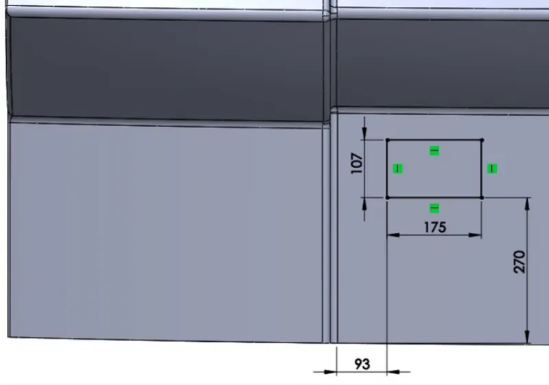
Figure 100: Sketch on Plane4
- Create an extruded boss/base for the above sketch offset from the surface to the offset distance of 5mm directed outwards.
- Select the plane4 again and create a new sketch by click on the blue surface of the previous extrude and convert the rectangle sketch. Offset the sketch to the offset distance of 5mm directed inwards.
- Create an extruded boss/base for the above sketch offset from the surface to the offset distance of 5mm directed outwards.
- Create a fillet of 2mm radius on the above extruded base.
- Select the deck surface of the hull and create a new sketch by drawing a line of 710mm such that the left endpoint of the line is coincident to the lower edge of the rear seat and 850mm below the left corner of the deck surface.
- Create a new plane using the reference plane geometry by selecting the previous sketch as the first reference and the deck surface as the second reference.
- Create a new sketch on the new plane with dimensions as shown in figure
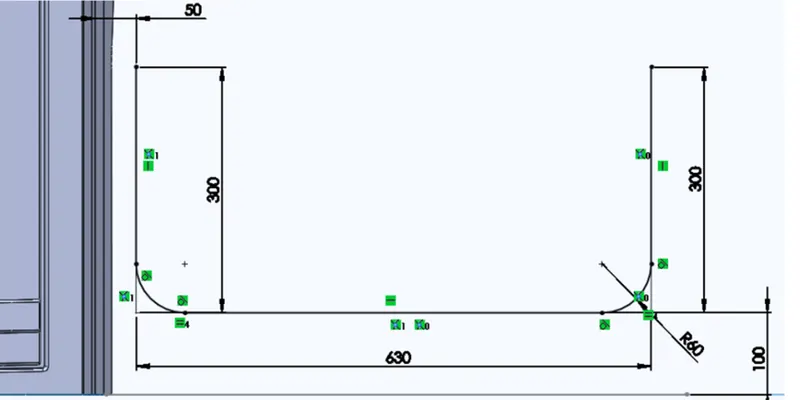
Figure 101: Sketch on the new plane
- Create a new plane using reference geometry feature by selecting the right line of the above sketch as the first reference and the upper right endpoint of the previous sketch as the second reference.
- Create a circle of 40mm diameter on the newly created plane.
- Create a solid sweep by selecting the circle sketch as the profile and the line sketch as the profile.
- Create a new sketch on the Plane5 with dimensions as shown in figure
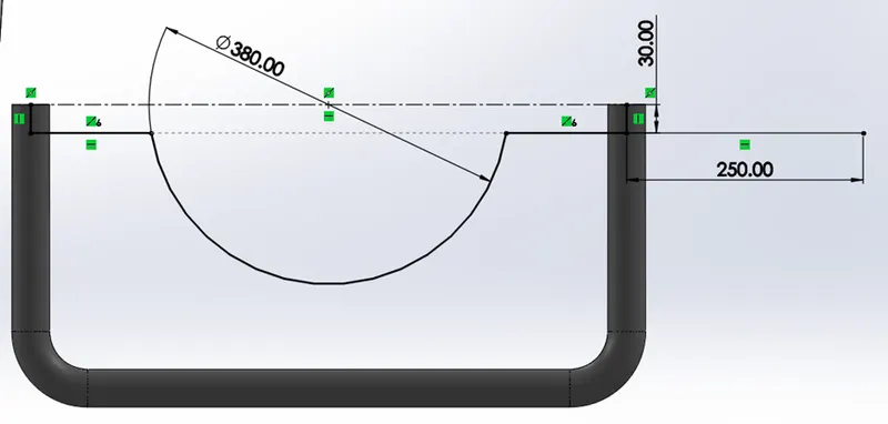
Figure 102: Sketch on the Plane5
- Create a new plane using reference geometry feature by selecting 250mm horizontal line of the above sketch as the first reference and the right endpoint of that line as the second reference.
- Create a circle of 30mm diameter on the new plane such that circle centre is coincident to the right endpoint of the 250mm line.
- Create a solid sweep by selecting the circle sketch as the profile using Sweep feature.
- Mirror the railing by selecting the appropriate face as the Mirror face and select the complete body as Mirror body using Mirror pattern feature.
- Mirror the rear seat by selecting the Midplane as the Mirror face using Mirror pattern feature.
- Mirror the pillow by selecting the Midplane as the Mirror face using Mirror pattern feature.
- Mirror the railing by selecting the Midplane as the Mirror face using Mirror pattern feature.
- Create a new sketch of the flagstaff on the Midplane with dimensions as shown in figure
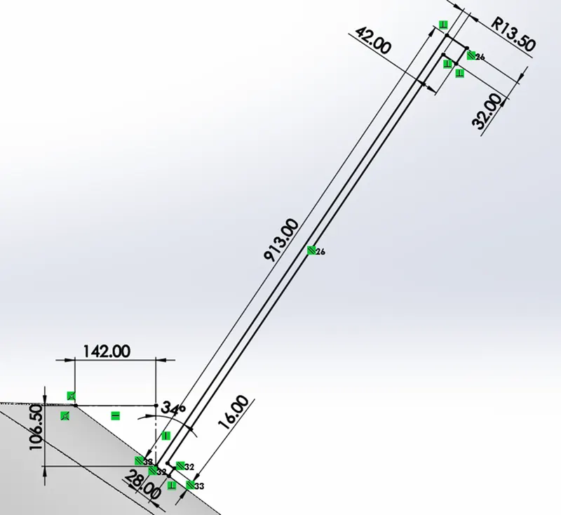
Figure 103: Sketch of flagstaff
- Create a revolve of the above flagstaff sketch by selecting the 913mm line of the above sketch as the axis of revolution.
- Create a fillet of 40mm radius on the upper edge of the flagstaff
- Create a distance-distance chamfer of 20mm and 3mm as direction1 and direction2 on the lower edge of the flagstaff
- Create a 3D sketch using spline to stimulate the flag contour on the flag staff.
- Create a surface fill on the above 3D sketch of the flag contour.
- Change the colour of the bodies of the rear seat to white colour.
- Change the colour of the two railings and the flag staff of the rear seat to grey.
- Change the colour of the flag to red.
- Change the colour of the locks and hinges to grey colour.
- Change the colour of the pillows to light grey.
- Change the colour of the lights to a custom light yellow by changing the RGB numbers to 255, 255, 277.
- Finally, save the file.
9. Superstructure
A superstructure is a upward extension of an existing structure above a baseline called ground level and it usually serves the purpose of the structure’s intended use. A superstructure is a decked structure on the freeboard deck, extending from side to side of the ship.
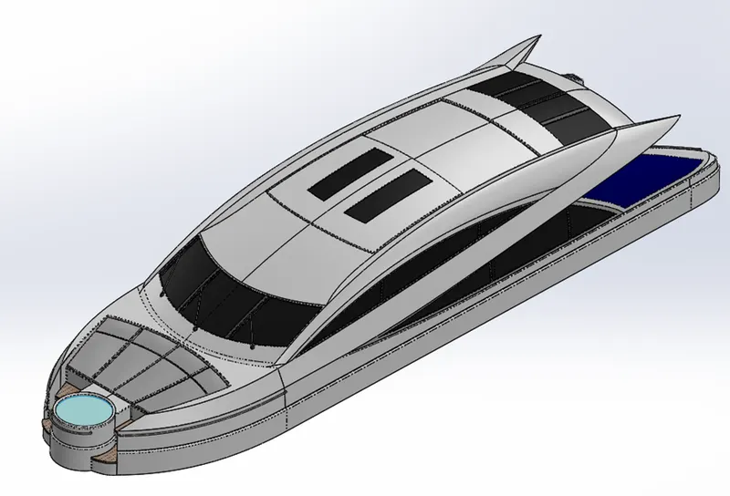
Figure 104: Superstructure
Commands
- Sketch Picture
- 3D sketch
- Line
- Spline
- Circle
- Rectangle
- Centre point arc
- Extruded surface
- Swept surface
- Ruled surface
- Knit surface
- Trim surface
- Extend surface
- Filled surface
- Lofted surface
- Revolved surface
- Fillet
- Chamfer
- Project curve
- Reference curve
- Convert entities
- Split
- Split line
Procedure
- Open the Blueprint setup and save as the file by renaming as Superstructure.
- Import the deck surface of the Hull as the interface surface using Insert part feature.
- Select the deck surface and create a sketch using lines and spline with dimensions as shown in figure
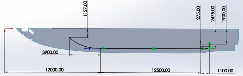
Figure 105: Sketch on the Deck surface
- Create a surface extrude for the above sketch to 600mm directed upwards.
- Create a new plane using reference geometry feature by selecting vertical edge of left end of the surface as the first reference and face as the second reference.
- Sketch a horizontal line of 50mm on the new plane such that the right endpoint of the line has pierce relation with the corner point of the surface extrude.
- Create a 3D sketch by converting the upper edge of the surface extrude using convert entities tool.
- Create a surface sweep using horizontal line as the profile and the 3D sketch as the path.
- Knit all the two surfaces using surface knit option.
- Create a fillet of 35mm radius on the upper edge of the surface extrude.
- Create a ruled surface to 500mm and angle of 5⁰ with deck surface as reference vector and four outer edges of the surface as Edge selection.
- Create a sketch on the Midplane with lines of 7000mm and spline with dimensions such that the line is parallel to the upper edge of the surface as shown in figure

Figure 106: Sketch on Midplane
- Trim the upper surface by selecting the above sketch as Sketch tool using Trim tool.
- Create a new sketch on Midplane by converting the two left edges and spline of the structure having tangency with the line with dimensions as shown in figure
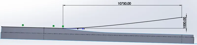
Figure 107: Sketch on Midplane
- Create a new sketch on Top plane and convert the four inner edges of the surface extrude and sketch a spline with tangency to the line with dimensions as shown in figure
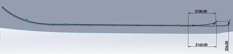
Figure 108: Sketch on Top plane
- Create a projected curve using both the sketches above
- Create a new sketch on the top plane by offset the edges of the superstructure to the offset distance of 200mm directed inwards and then sketch a spline with tangency to the offset line with dimensions as shown in figure

Figure 109: Sketch on Top plane
- Create a new sketch on Midplane using lines and spline having tangency relation between them with dimensions and similar to the blueprint as shown in figure
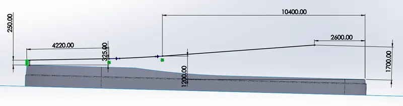
Figure 110: Sketch on Midplane
- Create a projected curve from both above sketches using Projected Curve feature
- Create a 3D sketch of a line connecting both the curves at the left end of the curves.
- Create another 3D sketch of line connecting both the curves at the end of the edge of the surface extrude.
- Create a 3D sketch by converting the curve1 using convert entities feature and trim the lines till the end of the previous sketches using Power trim tool
- Create another 3D sketch by converting the curve2 using convert entities feature and trim the lines till the end of the previous sketches using Power trim tool.
- Create a surface loft selecting previous sketches as the Loft profile and guide curve.
- Create another 3D sketch of line connecting the curves at right end.
- Create a 3D sketch by converting the curve1 and then trim converted line except the last left end. Draw a spline with no midpoints connecting the line having tangency with lines as shown in figure

Figure 111: 3D Sketch of spline
- Create another 3D sketch and convert the curve1 by convert entities and trim the left end part of the converted line.
- Create a surface fill by selecting the above three 3D sketches appropriate edges along with edge of previous Surface loft as fourth references.
- Create a 3D sketch of straight line of 700mm as shown in figure
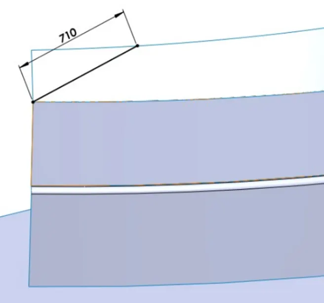
Figure 112: 3D sketch of straight line
- Selecting the above 3D sketch as the trim tool trim the upper surface using Power trim option.
- Create a new plane by selecting the right endpoint of the surface extrude as the first reference and the vertical edge connected to that point as the second reference.
- Create a horizontal line of 30mm on the newly created plane such that the left endpoint is connected to the corner of the surface extrude.
- Create a 3D sketch by converting the edges of the surface extrude as shown in figure
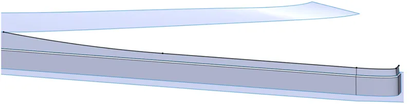
Figure 113: 3D sketch of converted edges.
- Create a surface sweep by selecting the horizontal line sketch as the profile and 3D sketch as the path.
- Knit the surfaces of the superstructure by using Knit surface feature.
- Create a new plane by selecting appropriate point and edge as the first reference and second reference respectively as shown in figure
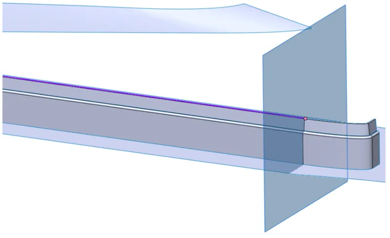
Figure 114: References selected for new plane
- Create a new sketch on the new plane by creating a spline without any midpoint and having vertical relation at its lower endpoint with dimension as shown in figure
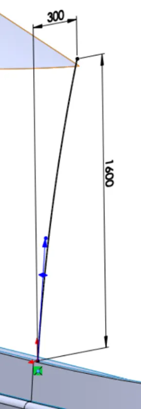
Figure 115: Sketch of spline on new plane
- Create a 3D sketch by converting the two edges using convert entities feature as shown in figure
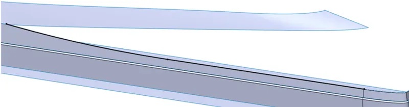
Figure 116: 3D sketch of the converted edges
- Create a surface sweep by selecting the spline of the above sketch as the profile and the 3D sketch as the path.
- Create a new sketch on the Midplane by converting the edges as shown in figure

Figure 117: sketch on the Midplane
- Trim the upper surface of the surface sweep using above sketch as trim tool.
- Create a new sketch on the Midplane by drawing a spline of window curve as shown in blueprint and drag the lower spline arrow to match the curve of the blueprint as good as possible.
- Add dimensions to the spline of 5300 and 1520mm as horizontal and vertical dimension respectively and a distance of 3030mm between the lower endpoint of the spline and the right corner of the superstructure.
- Trim the right surface by selecting the above sketch as the trim tool using Power trim feature.
- Create a new sketch on the Midplane by converting the edges as shown in figure
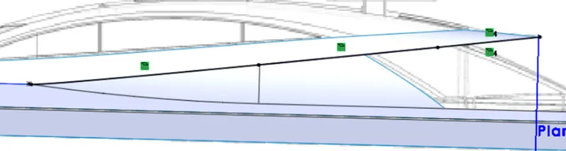
Figure 118: Sketch on Midplane
- Create a surface extrude of 3000mm for the above sketch directed frontwards.
- Trim the front surface of the above surface extrude using Power trim tool.
- Knit surfaces of the superstructure using Surface knit feature.
- Create a 3D sketch of the straight line by connecting the endpoints of the line with the superstructure as shown in figure
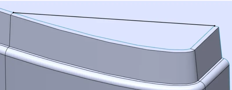
Figure 119: 3D sketch on the superstructure
- Create a surface fill by selecting the above sketch and the two edges of the superstructure.
- Knit the surfaces of the surface fill and all other surfaces of the superstructure using Surface knit option.
- Select the top surface of the surface fill and draw a spline with it left side having tangency with the surface sweep and right point having horizontal relation with the endpoint of surface sweep.
- Pull the arrows of the spline to match the curve.
- Trim the upper surface by selecting the above spline sketch as the Trim tool using Power trim feature.
- Create a 3D sketch by converting the edges as shown in figure
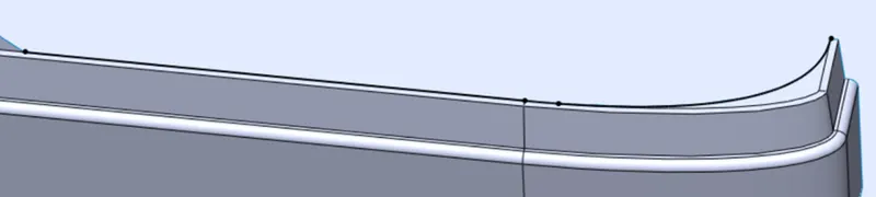
Figure 120: 3D sketch on the superstructure
- Create a new sketch on plane2 of a spline with dimensions as shown in figure
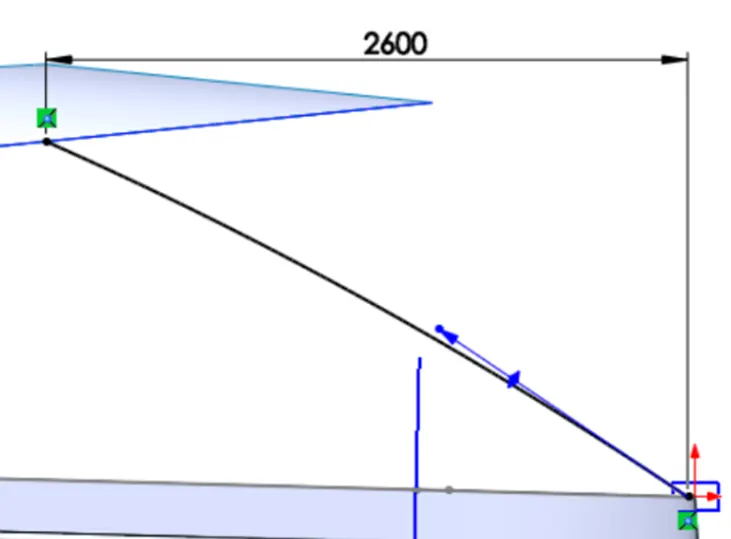
Figure 121: Sketch on Plane2
- Create a 3D sketch of spline with tangency relation between the left side of spline and Surface sweep as shown in figure
Figure 122: 3D sketch of spline
- Create a surface loft by selecting the above 3D sketches and edge of the superstructure as loft profiles and guide curves
- Knit the surfaces of the superstructure using Surface knit feature.
- Create a new sketch on the spline without any midpoints and drag the arrows of the spline to match the outer window curve of the blueprint. Add fix relation on the spline to fully defined the sketch as shown in figure
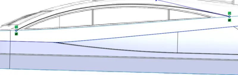
Figure 123: Sketch on Midplane
- Create a new sketch on the Top plane and convert the edges of superstructure.
- Create a projected curve from the both sketches using Projected curve feature.
- Create a new sketch on Midplane by drawing spline without any midpoints as shown in figure and add fix relation on the spline to fully define the sketch
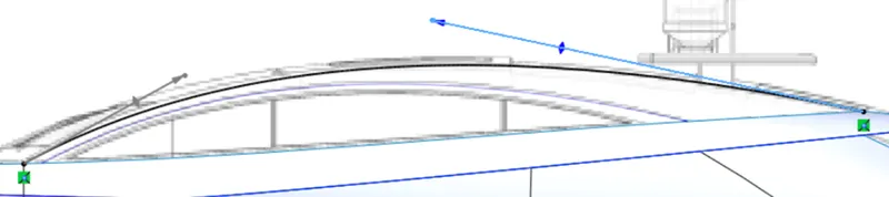
Figure 124: Sketch on Midplane
- Create a new sketch on the top plane of 150mm vertical centreline with a spline without any midpoint such that its endpoints are connected to the centreline and end of the surface fill as shown in figure

Figure 125: Sketch on Top plane
- Create a projected curve from both the above sketches using Projected Curve feature
- Create a 3D sketch by converting the edge of the surface fill1 and trim the front part of the converted spline
- Create another 3D sketch by drawing a spline connecting both the curves created above.
- Create a surface loft by selecting the above curves as the loft profiles and 3D sketches above as the loft guide curves.
- Create a sketch on the Top plane by offset the edge of above created surface loft to 220mm. Then, draw a spline of 1300mm as shown in figure

Figure 126: Sketch on the top plane
- Next, trim the left side part of the spline and add tangency relation between the offset line and the right-side arrow of the spline.
- Create a new sketch on the Midplane by drawing two vertical centreline connected at the grey endpoints of the previous sketch and continue with spline as shown in figure
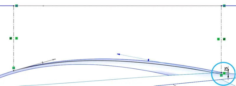
Figure 127: Sketch on the Midplane
- Create a projected curve using both the above sketches
- Create a 3D sketch of straight line such that its endpoints connected to the curve and the surface loft5
- Create another 3D sketch by converting the edge of the surface loft5 using convert entities and the trim the front part of the spline.
- Create a surface loft using above 3D sketches and the curves as loft profiles and loft guide curves.
- Next, create a new sketch on the Midplane with the spline as shown in figure
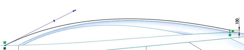
Figure 128: Sketch on Midplane
- Create a 3D sketch by drawing a spline without any midpoints and connect the spline to previous spline sketch and surface-loft6. Add along x direction on the upper arrow of the spline as shown in figure
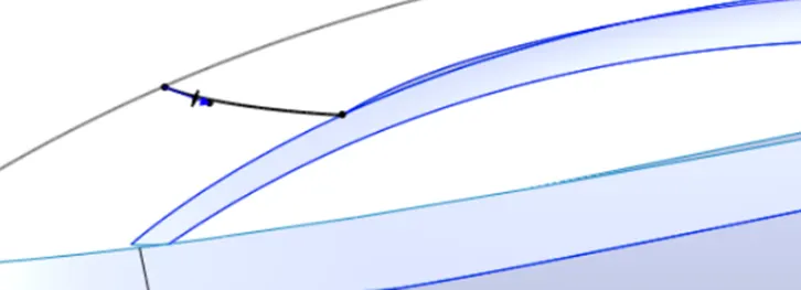
Figure 129: 3D sketch of spline
- Create another 3D sketch by drawing a spline without any midpoint and connected to the spline and the surface loft6 at the right end. Add along X direction relation on the upper arrow of the spline.
- Create a 3D sketch by drawing a spline without any midpoint and connected to the middle of the spline sketch and the surface loft6 and add along X direction relation on the upper arrow of the spline. Add fix relation on the spline.
- Create a surface loft by selecting the above 3D sketches and the edge as the profile loft and guide curve.
- Create a 3D sketch of spline without any midpoint as shown in figure
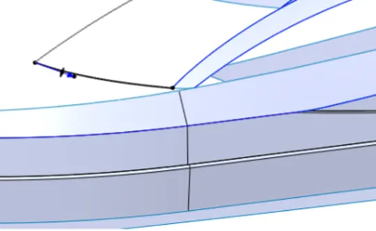
Figure 130: 3D sketch of spline.
- Create a surface loft by selecting the above 3D sketch and the edges of the superstructure as the loft profiles and loft guide curves.
- Create a 3D sketch by converting the upper edge of the surface extrude as shown in figure
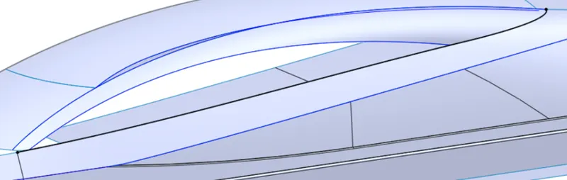
Figure 131: 3D sketch of converted edge
- Create a ruled surface to 1000mm and angle of 4⁰ for the above sketch as the edge selection.
- Create a new sketch on the Midplane by drawing a spline of the window curve and drag the spline arrows to match the curve as good as possible.
- Trim the upper surface by selecting the above sketch as trim tool using Power trim tool.
- Knit the surfaces of the superstructure keeping the knitting tolerance to 0.1mm using Surface knit option.
- Create a surface loft selecting the appropriate edges as the loft profiles and loft guide curves.
- Extend the surface of the surface loft 7 to 500mm.
- Create the remaining surface of the superstructure by sketching on the required plane and drawing splines as shown in the blueprint. Also use the features such as surface extrude, surface extend.
- Trim the unwanted surfaces to get the view representation as in the blueprint.
- Also, Knit the newly created surfaces of the superstructure.
- The front pool of the superstructure provided with the water feature is created by using the Extruded Boss/Base, extruded cut and fillet with water appearance.
- The railing at the pool and at the superstructure is created using the features such as Reference geometry, Spline and solid sweep.
- The back door of the superstructure is created by the extruded cut, fillets and reference geometry features.
- The front windshield is created by using tools as extruded cut and its wipers are created by 3D sketches and reference plane along with swept boss/base.
- The front mattress bodies at the jacuzzi area of the superstructure is created using the Extruded cut feature, dome and fillet.
- The Portholes for the Superstructure is created by using Extruded surface, Trim surface and extend surface.
- Then all the surfaces generated were knitted together to form solid body.
- The superstructure consists of two surface bodies and five solid bodies.
- The other half was mirrored and the proper fillets and appearance are added.
- Appearance is applied on the super structure parts as required
- Finally, save the part.
10. Radar mast
A mast is a vertical ship structure mounted on the top of bridge and forward the forecastle towards the ship’s bow. It accounts for the support platform for the ships derrick and hold the necessary equipment’s such as radars, navigation light and ships horn in case of foremast. They are made of high tensile steel with added rigidity based on the size of derricks it holds. Other than that a ships main mast is also used to hoist ships flag.
Out of different parts of ship the main job of mast is to hold necessary equipment such as radar receiver, navigation lights, ships horn, flags and derrick in some case.
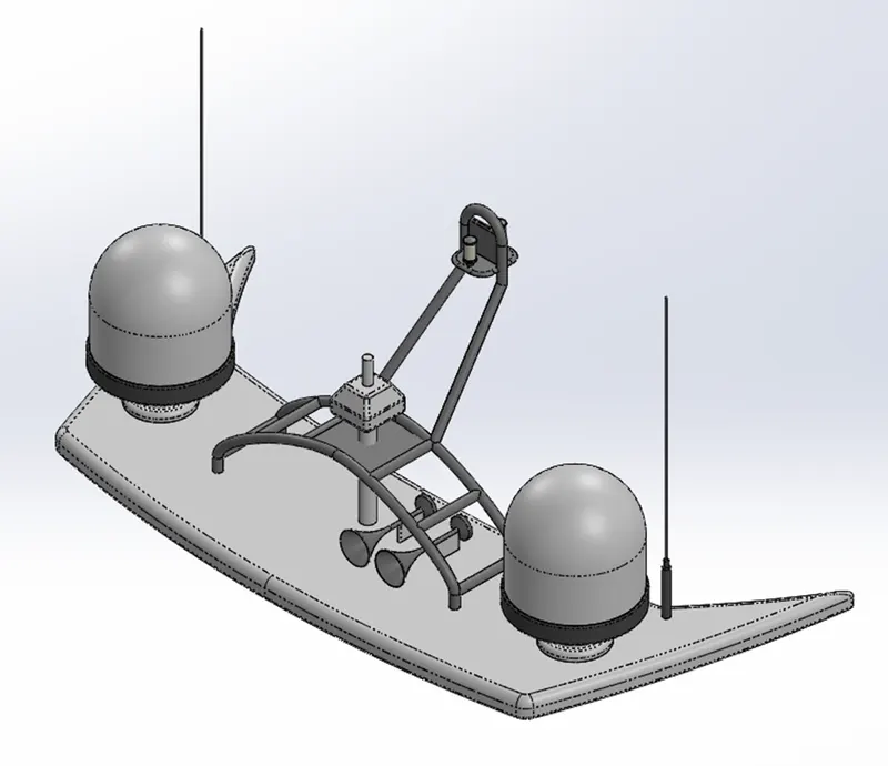
Figure 132: Radar mast
Commands:
- Sketch Picture
- Line
- Rectangle
- Arcs
- Extruded Boss/Base
- Lofted Boss/Base
- Revolved Boss/Base
- Swept Boss/Base
- Reference plane
- Projected Curve
- Fillet
- Mirror
- Dome
- Shell
Procedure:
- Open the Blueprint setup file and save as the file by renaming as “Radar mast”.
- Import the top surface of the superstructure as interface surface using Insert part feature.
- Create the base of Radar mast by creating its sketch using spline as on the blueprint and then boss extrude the sketch. Apply fillet on the edges of the base of radar mast.
- Create a body of the radar is created using extruded boss feature and apply the fillet on the edges of the radar.
- The antenna of the radar mast is created using the extruded boss/base feature and fillet is provided on its edges.
- Create a connecting rod of the lamp stand using Swept boss/base and the mirror tool.
- Create the mast lamp of the radar mast using the projected curve and then swept boss/base feature and apply fillet feature on the edges of the mast lamp.
- Stand of the radar mast are created using extruded boss/base and apply the fillet on the edges of the extruded boss.
- The horn of the radar mast is created by revolved boss/base, dome and shell feature on it.
- Mirror the entire half of the radar mast by selecting the Mid plane as the reference plane.
- Apply the appearances of the radar mast as required on the bodies of the radar mast.
- Finally, save the part.
Assembly of the American Predator Yacht:
- Import the hull of the predator yacht and the hull is fixed automatically in the assembly.
- Next, import the superstructure part in assembly and the superstructure is fixed automatically in the assembly.
- Import the radar mast part and the radar mast is fixed automatically in the assembly.
- Part file of the front seat is imported and the front seat is fixed automatically in the assembly.
- Part file of the middle seat is imported and the middle seat is fixed automatically in the assembly.
- Import the rear seat part and coincident relation is added between the deck surface of the hull and bottom surface of the rear seat with its distance is 0mm.
- Create another coincident mate between the mid plane of the hull and the midplane of the rear seat with its distance to 0mm.
- Create coincident mate between the lower vertex of the rear seat and the vertex of the hull with its distance as 50mm.
- Import the garage door and coincident mate is added between the mid plane of the hull and right plane of the garage door with distance to 0mm.
- Create concentric mate between the hinge tube of the hull and hinge hole of the Garage door
- Import the propeller and add concentric mate between the axis of the hull and propeller hole.
- Along with this also add coincident mate between the surface of the hull and the back surface of the propeller.
- Import the radar part and add concentric mate between the axis of the radar mast and hole of the radar. Also, add coincident mate between the surface of the radar mast axis and surface of the radar hole.
- Finally, Save the assembly file.
Photorealistic Rendering:
Photorealistic rendering creates high quality images or motion graphics if available so as to look appealing in various environment and backdrops. Rendering is the process of creating realistic images of the Photorealistic model with the environment. Rendering is done on two ways in Solidworks:
- Photoview 360
- It is inbuilt in SOLIDWORKS. After adding the Photoview 360, render tools can be used in SOLIDWORKS.
- Decals are added on the required faces of the chopper and by using Edit decals and appearance changes can be made.
- Various option such as Preview window, Final Render, Render region, Scene Illumination Proof Sheet, Schedule Render, recall last render can be used.
- From viewpoint- Camera and light options are used for setting up camera view and lighting of the scenes.
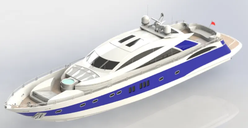
Figure 133: Render of Predator Yacht from camera viewpoint
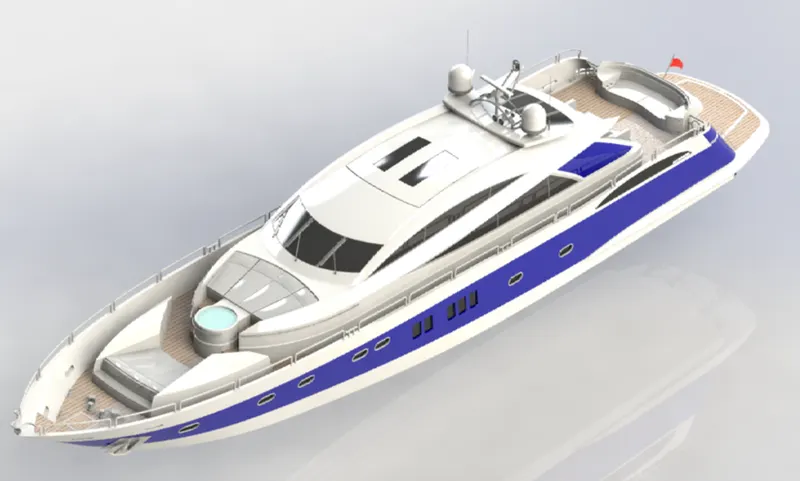
Figure 134: Render of Predator Yacht in Isometric view
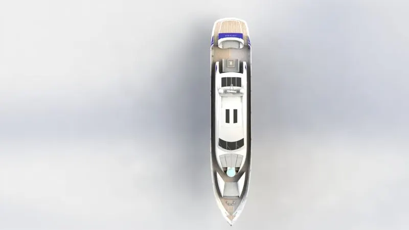
Figure 135: Render of Predator Yacht in Top view
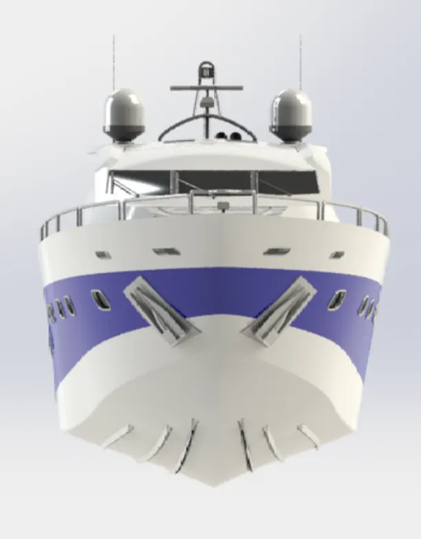
Figure 135: Render of Predator Yacht in Front view
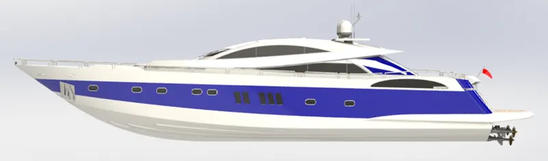
Figure 136: Render of Predator Yacht in Side view
2. Solidworks Visualize
- It is a separate render tool provided under SOLIDWORKS professional.
- It uses either the CPU or GPU for rendering quality images.
- Solidworks visualize quickly and easily creates professional, photo-quality images, animations and other interactive 3D contents to get your product to the product faster.
- Visualize professional adds an array of features including animations, custom lighting, VR, 360 interactives, and much more.
- Assembly file is imported and selected part appearance can be altered by using the appearance option in the appearance tab.
- Background are setup with wide range of HDR images and backgrounds from the scene tab.
- Background brightness, camera setup and lighting, rotation, gamma can be altered as required from the scenes tab.
- Camera view can be added or used from the assembly as required.

Figure 137: Visualise of the predator yacht in sunset view
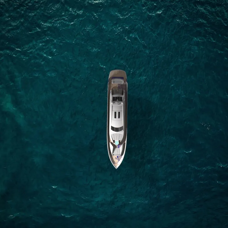
Figure 138: Visualise of Predator Yacht from top view
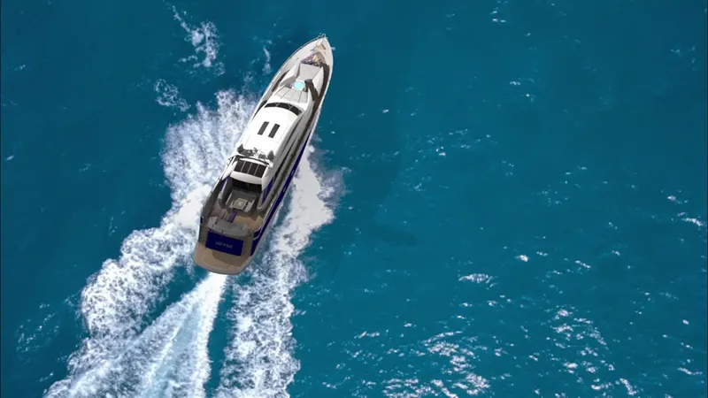
Figure 139: Visualise of the predator yacht surfing
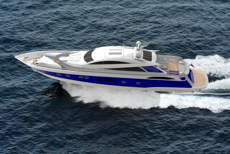
Figure 140: Visualise of predator yacht surfing
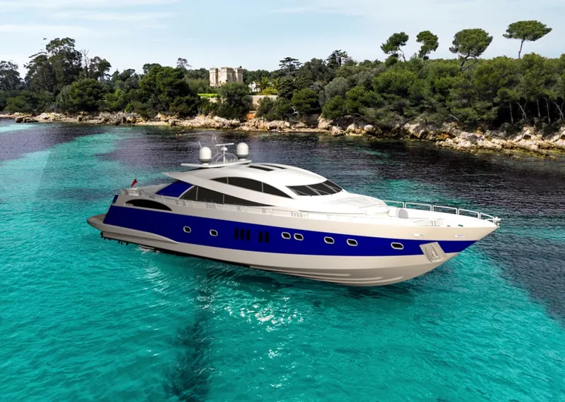
Figure 141: Visualise of Predator Yacht at shore view
Conclusion:
Design of all parts of the Predator yacht is done successfully using SOLIDWORKS. Assembly of all the exterior parts of the Yacht is done in SOLIDWORKS assembly environment and Photorealistic rendering of the Predator Yacht is successfully completed in both Photoview 360 and Solidworks Visualize.
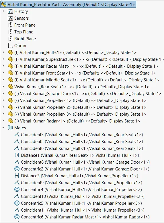
Figure: Yacht Assembly_Sketch Tree(1)
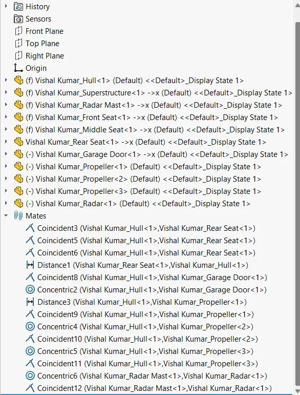
Figure: Yacht Assembly_Sketch Tree(2)
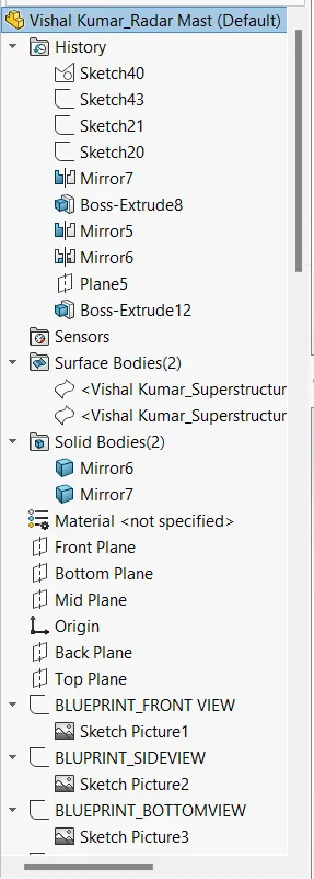
Figure: Radarmast_Sketch Tree(1)
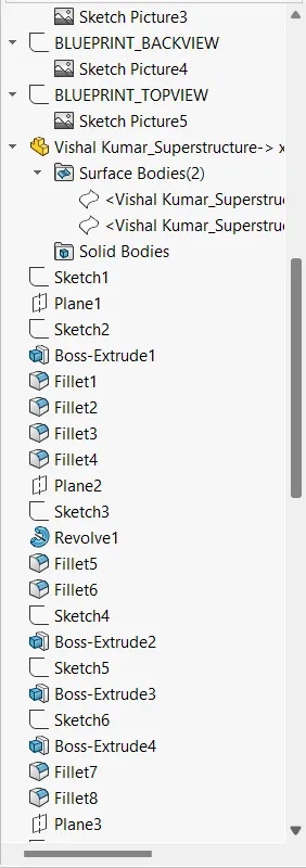
Figure: Radarmast_Sketch Tree(2)
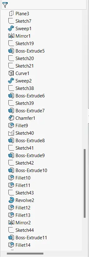
Figure: Radarmast_Sketch Tree(3)
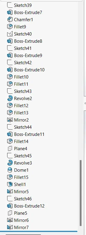
Figure: Radarmast_Sketch Tree(4)