Radar Mast & Final Assembly of Yacht
Project Report
Modelling and Rendering of Sunseeker Predator Yatch
Aim:
- To sketch and design the parts of Yatch using Solidworks.
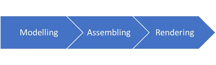
- To assemble the modelled parts of the chopper by using the Solidworks assembly environment.
- To create photorealistic rendered images of the yatch using Solidworks visualize.
Introduction:
Sunseeker has been building boats since 1969 and is one of the largest motor yacht builders in the world. With approximately 150 boats produced each year and their range exceeding 20 models to choose from, it's safe to say that the Sunseeker brand will continue its pursuit for quite some time. This is a very subjective question as Sunseeker builds a particular style of yacht for a particular style of boating, one that may not appeal to someone that loves sportfishing boats or center-consoles. By looking at both industry awards and a good volume of boats sold, we can assume the answer. Sunseeker Yachts are widely considered a good boat builder as they are often recognized through marine industry awards, like the World Yacht Trophies, but there have also been more than 450 used Sunseekers sold since the beginning of 2021.
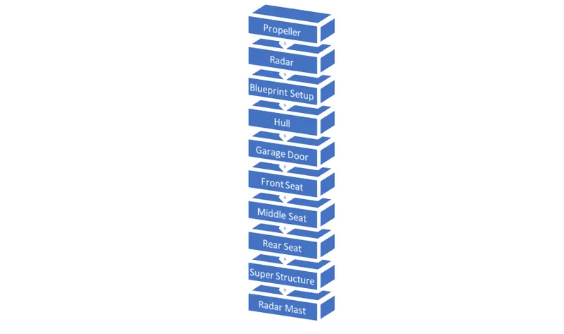
The following parts of yatch are:
Design Approach:
Part Modelling:
Part modelling is the process of creating a virtual prototype of something by modelling each individual part separately, which can then assemble together to create the model of the final product.
Commands used in Modelling:
- Sketch: The sketch is the basis for a 3D model. You can create a sketch on any of the default planes (Front Plane, Top Plane, and Right Plane), or a created plane. You can start by selecting: Sketch entity tools (line, circle, and so on).
- Trim Entities: You can use Power trim to trim multiple, adjacent sketch entities by dragging the pointer across each sketch entity
- Extend Entities: Extend command to edit entities so they have common boundary edges. Extend expands parts of entities to the intended boundary edge, letting you close polygons precisely or extend entities to the proper boundary edge. As drawing an entity expands, they do not change direction. A Line remains a Line, and an Arc remains an Arc.
- Convert Entities: You can create one or more curves in a sketch by projecting an edge, loop, face, curve, or external sketch contour, set of edges, or set of sketch curves onto the sketch plane.
- Offset Entities: Offset entities takes a copy of your existing geometry and copies it at an offset. Instead of recreating geometry, you can use this to quickly sketch based on model geometry. Offset entities are a great tool for enlarging or shrinking your sketch geometry.
- Linear Pattern: The Linear Pattern Command is used to drive features, faces, or bodies in a linear direction. This feature helps save time by cutting down the repetitive movements of adding a bunch of holes or other forms of geometry.
- Circular Pattern: A circular pattern is a radial array of objects around a Center point in a sketch. Axis in a part or assembly.
- Extruded Boss/Base: One of the oldest commands in the SOLIDWORKS software is the boss/base extrude command. An Extruded Boss/Base feature will allow you to take a 2D sketch and add thickness to it in the 3D.
- Extruded Cut: Extrude tool is used to extend a sketched profile in one or two directions as either a thin feature or a solid feature. An extrude operation can either add material to a part (in a base or boss) or remove material from a part.
- Revolve Boss/Base: Revolves add or remove material by revolving one or more profiles around a centerline. You can create revolved boss/bases, revolved cuts, or revolved surfaces. The revolve feature can be a solid, a thin feature, or a surface.
- Revolve Cut: It helps to remove materials from 3D models possess axis symmetry.
- Swept Boss/Base: Its helps to sweeps a closed profile through an open or closed path.
- Loft Surface: The loft feature is an important tool for (surface) modeling in SolidWorks. The loft feature creates a shape by making transitions between multiple profiles and guide curves.
- Filled Surface: The Filled Surface feature constructs a surface patch with any number of sides, within a boundary defined by existing model edges, sketches, or curves, including composite curves.
- Surface Trim: A trimmed surface has two parts: a surface that underlies everything and defines the geometric shape, and trimming curves that mark sections of the underlying surface that are trimmed away. Trimmed surfaces are created with commands that trim or split surfaces with curves and other surfaces.
- Surface Knit: Knit surfaces absorb the surface bodies you used to create them. Create a solid body when the knit surfaces form a closed volume, or leave as a surface body. Select Merge entities to merge faces with the same underlying geometry.
- Offset Surface: The offset surface tool is useful way of creating a series of deposit or erosion contact surfaces from a reference mesh. The surface can be offset from the reference mesh by points or by a fixed distance, and additional options for offsetting to points can be adjusted once the surface has been created.
- Ruled Surface: The Ruled Surface command creates surfaces that extend out in a specified direction from selected edges.
- Boundary Surface: The boundary surface feature lets you create surfaces that can be tangent or curvature continuous in both directions.
- Thicken: Thicken features use predetermined surface features or quilt geometry to either add or remove thin material sections in your designs. The surface features or quilt geometry provide you with greater flexibility within your design and enable you to transform that geometry to better meet your design needs.
- Shell: The shell tool hollows out a part, leaves open the faces you select, and creates thin-walled features on the remaining faces. If you do not select any face on the model, you can shell a solid part, creating a closed, hollow model. You can also shell a model using multiple thicknesses.
- Split: Split tool projects an entity (sketch, solid, surface, face, plane, or surface spline) to surfaces, or curved or planar faces. It divides a selected face into multiple separate faces. You can split curves on multiple bodies with one command.
- Dome: The software calculates the distance using the radius of the arc as a basis for the dome. It creates a dome that is tangent to the adjacent cylindrical or conical face.
- Pierce Relationships: A pierce relationship is required to ensure that two entities from different axis collide or cross paths – the center point of entities can be selected to move the sketch entity to a mutual position. To apply a pierce relation a line and a sketch point are required.
- Projected Curve: You can create multiple closed or open-contour projected curves from a single sketch. You can also use 3D sketches as input for the Projected Curve tool. The Projected Curve tool does not support projections of intersecting curves. You can project curves from 2D and 3D sketches, onto faces and planes.
- Composite Curve: You can create composite curves by combining curves, sketch geometry, and model edges into a single curve. Use a composite curve as a guide curve when creating a loft or a sweep. To create a composite curve: Click Composite Curve on the Curves toolbar, or click Insert, Curve, Composite.
- Fillet: Fillet/Round creates a rounded internal or external face on the part. You can fillet all edges of a face, selected sets of faces, selected edges, or edge loops.
- Chamfer: The chamfer tool creates a beveled feature on selected edges, faces, or a vertex.
- Split Line: The Split Line. tool projects an entity (sketch, solid, surface, face, plane, or surface spline) to surfaces, or curved or planar faces. It divides a selected face into multiple separate faces. You can split curves on multiple bodies with one command.
- Reference Plane: The most common type of reference plane is an offset plane. To create an offset plane, select the Reference Geometry drop down on the Command Manager and choose the Plane option. Once the option to create a plane is open, select a face or another plane and set a distance for the offset.
- Combine: The Combine tool helps us work with multibody part files. We have three operation types to choose from: Add, Subtract and Common. Some might know Combine has a Boolean operation.
- Helix & Spiral: The curve can be used as a path or guide curve for a swept feature, or a guide curve for a lofted feature.
- Appearances: It displays the colours of faces, features, bodies and the part.
Parts Description:
Propeller:
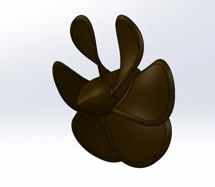
A propeller is a device with a rotating hub and radiating blades that are set at a pitch to form a helical spiral which, when rotated, exerts linear thrust upon a working fluid such as water or air.
Commands Used:
- Sketch Tools
- Revolve Boss/Base
- Reference Plane
- Loft
- Fillet
- Cut Extrude
- Linear Pattern
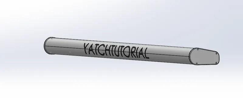
Radar:
A Radar (Radio Detection and Ranging) is an instrument that can detect surrounding objects using radio waves. Thus, in the maritime world, objects such as ships, buoys or birds can be detected by Radars. The use of short-wavelength microwaves allows a very accurate measurement of the direction in which the object is detected and the distance at which it is located. In addition to the maritime domain, Radars have many other applications such as meteorology and aerial surveillance.
Commands Used:
- Sketch Tools
- Extrude Boss/Base
- Reference Plane
- Mirror
- Fillet
- Cut Extrude
- Sketch Pattern
- Split line
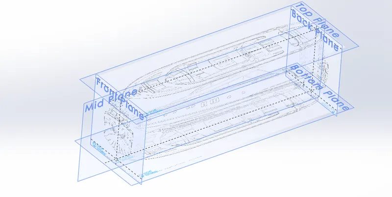
Blueprint Setup:
There are five different views (Front, Top, Side, Back & Bottom) used in the blueprint setup. By using the Sketch Picture option images are inserted and the required dimensions are given to the images.
Hull:
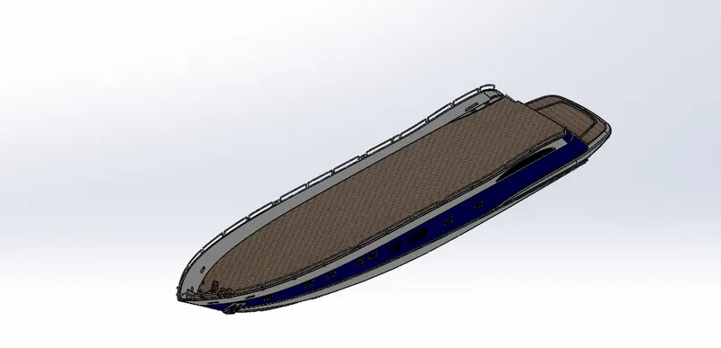
The hull of a ship is the most important as well as the most noticeable part of the ship. It is the watertight part of any vessel or even boat. It is defined as the water-tight enclosure of a ship. It protects the cargo and the machinery of the ship. It can also protect the boat from flooding and other structural damage. It is the part of the vessel which meets the ocean. The point or the line at which the hull of a ship meets the surface of the water is called the waterline. The hull of a ship can vary greatly depending upon the size or the type of the ship or vessel. Any structure like the deck of a ship, the mast, etc. can lie above or atop the hull of a ship. The following article talks about how the hull of a ship is designed, the factors that are taken into consideration while doing so, and what kind of a role it plays in the life of the ship as a whole.
Commands Used:
- Sketch Tools
- Surface Loft
- Surface Offset
- Surface Trim
- Surface Extrude
- Surface Knit
- Surface Fill
- Shell
- Extrude Boss/Base
- Extrude Cut
- Fillet
- Chamfer
- Reference Plane
- Sweep Boss/Base
- Dome
- Revolve Boss/Base
- Helix and Spiral
- Linear Pattern
- Projected Curve
- Mirror
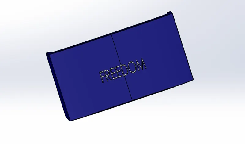
Garage Door:
A garage door is a large door on a garage that opens either manually or by an electric motor. Garage doors are frequently large enough to accommodate automobiles and other vehicles.
Commands Used:
- Sketch Tools
- Cut Extrude
- Shell
- Reference Plane
- Fillet
- Mirror
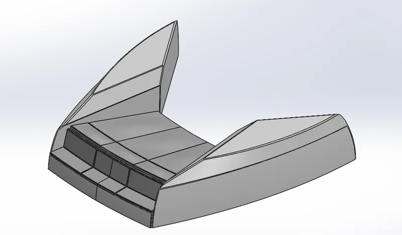
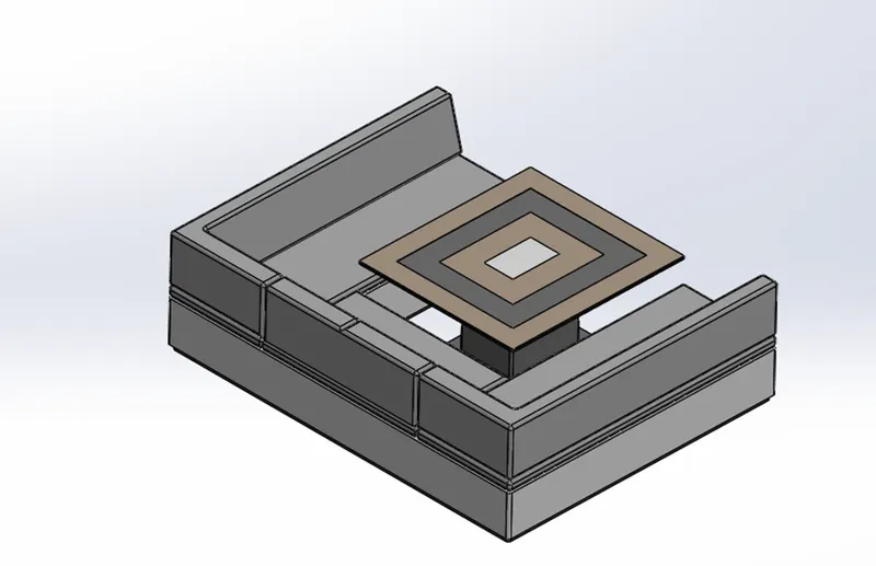
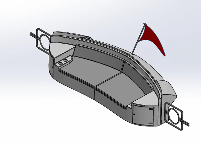
Front, Middle & Rear Seats:
The part of something on which a person sits.
Commands Used:
- Sketch Tools
- Extrude Boss/Base
- Extrude Cut
- Reference Plane
- Surface Fill
- Surface Trim
- Surface Sweep
- Surface Loft
- Surface Knit
- Chamfer
- Revolve Boss/Base
- Fillet
- Dome
- Ruled Surface
- Mirror
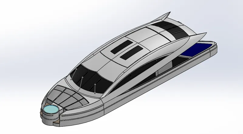
Super Structure:
A superstructure is an extended construction of any building or platform that rises above the rest of the building or platform in a distinct manner. The word comes from a combination of two Latin words, the Latin prefix ‘super’ means in addition or above or in excess of, whereas the stem word ‘structure’ means to build or to heap up. Thus, superstructure means to add a construction to an already existing structure. In ships this is the name given to the part of the ship that emerges from the deck. However, any mast, sails, any armaments or arsenal are not included in this category. The size of the superstructure has a great influence on the mobility of the vessels. They are designed in a manner, so that, they add value and hinder the speed and mobility in the least. The superstructure is mostly designed in fashion as well. This is because it is the most easily visible part of the ship, in fact it is the identification of the ship, and so the designers try to provide it with the identity that is unique.
The design may differ from ship to ship. Therefore, in some ships we may find it to be sticking out vertically and strongly from a relatively flat deck. The best examples of these are the aircraft carriers. These are huge in size and have a vast and flat deck that also acts as the runway for the aircrafts to take off and land. The lone standing constructed figure acts a multipurpose center. It is a control tower of the aircrafts, it is the operational center for all the activities on the vessel, and it is also the workstation of a majority of the technical staff.
Commands Used:
- Sketch Tools
- Extrude Boss/Base
- Extrude Cut
- Reference Plane
- Surface Fill
- Surface Trim
- Surface Sweep
- Surface Loft
- Surface Knit
- Chamfer
- Revolve Boss/Base
- Fillet
- Dome
- Ruled Surface
- Boundary Surface
- Thicken
- Mirror
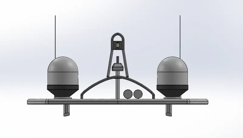
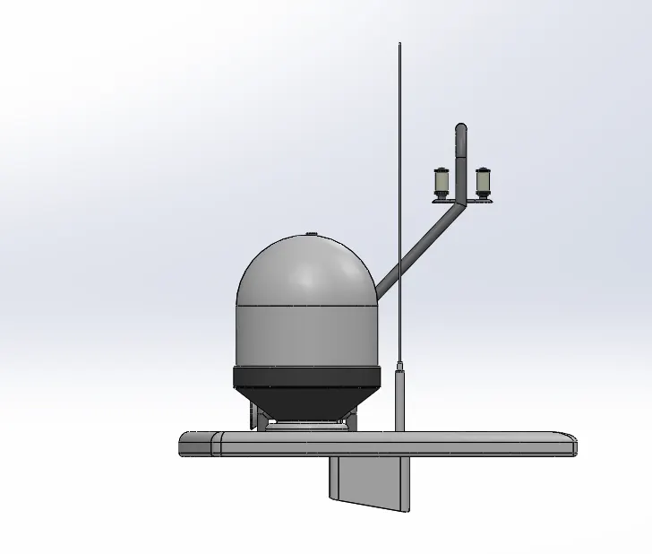
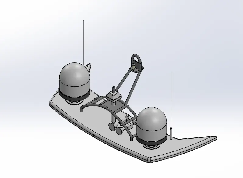
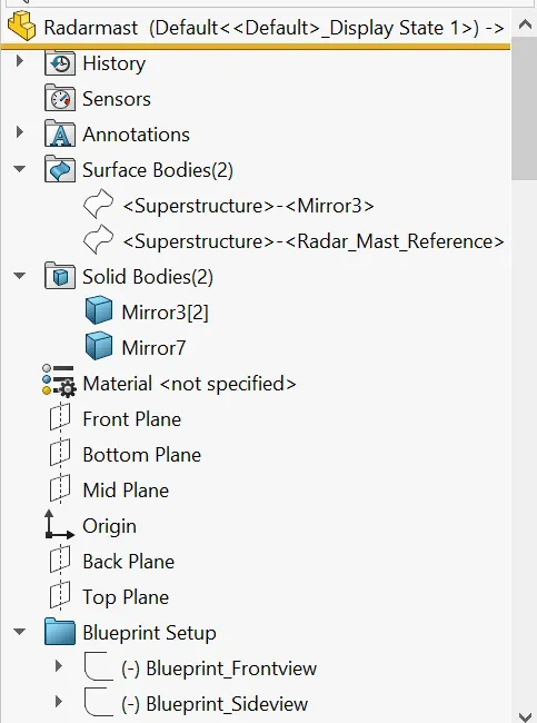
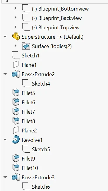
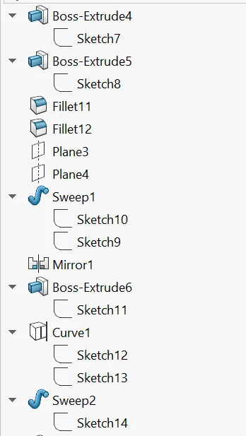
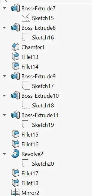
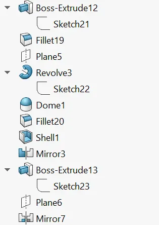
Radar Mast:
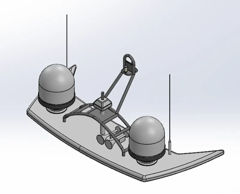
They are electronic navigation instruments that use a rotating antenna to sweep a narrow beam of microwaves around the water surface surrounding the ship to the horizon, detecting targets by microwaves reflected from them, generating a picture of the ship's surroundings on a display screen.
Commands Used:
- Sketch Tools
- Extrude Boss/Base
- Reference Plane
- Fillet
- Revolve Boss/Base
- Sweep Boss/Base
- Chamfer
- Mirror
- Dome
- Shell
Assembly of Sunseeker Predator Yatch:
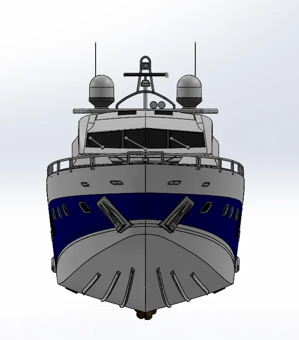
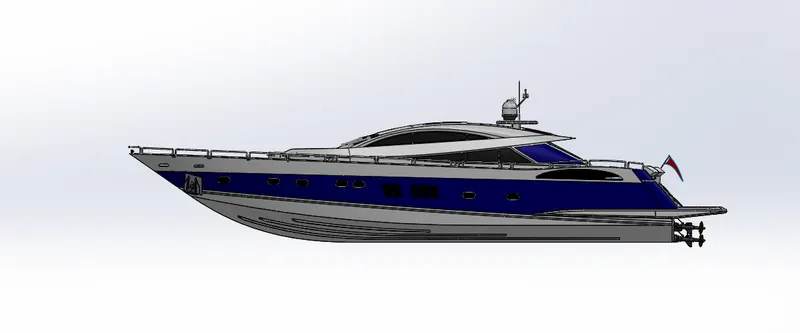
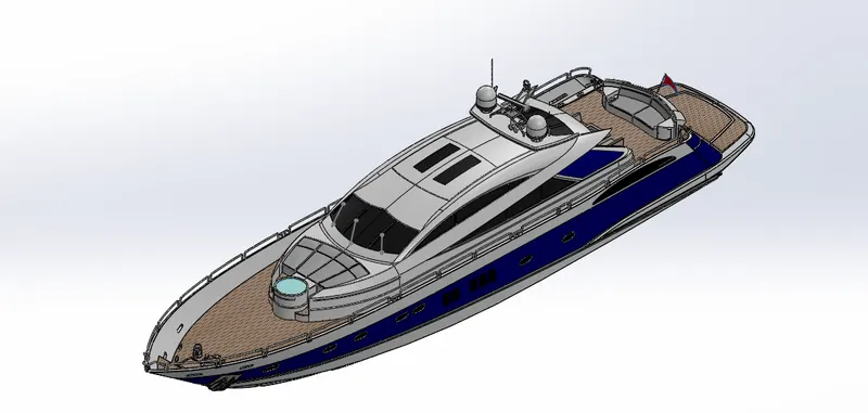
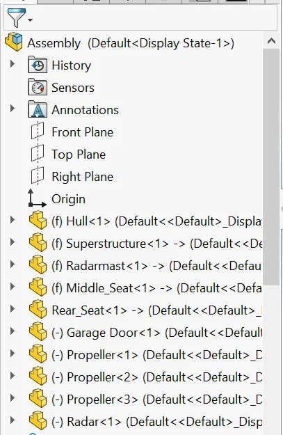
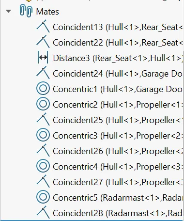
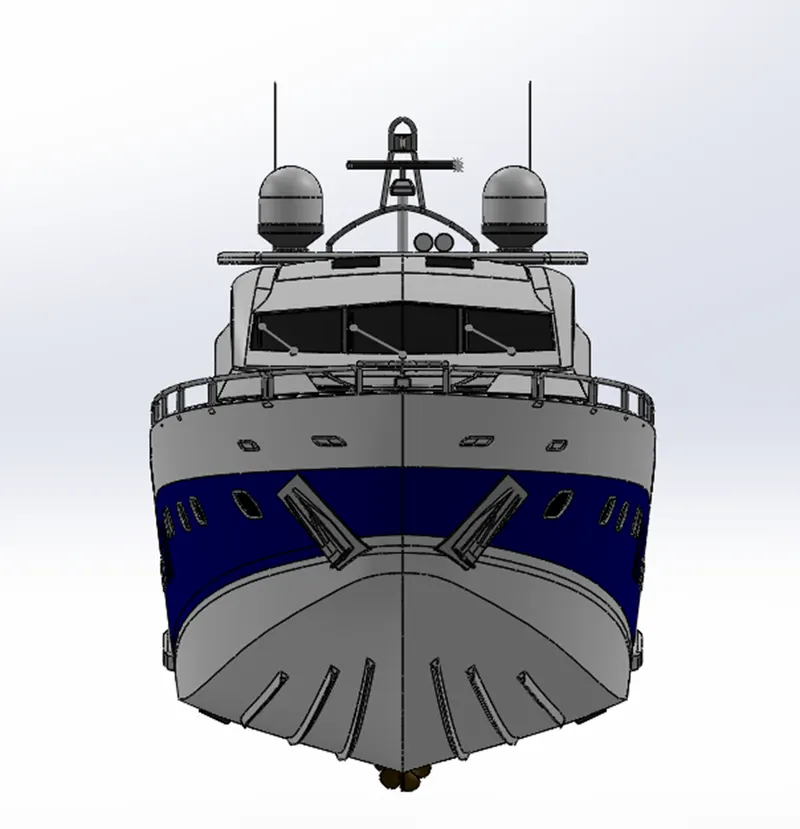
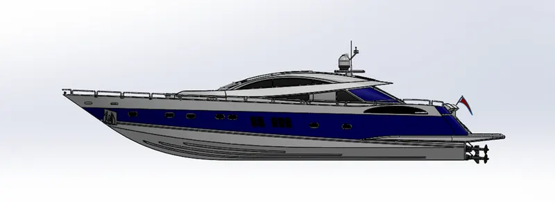
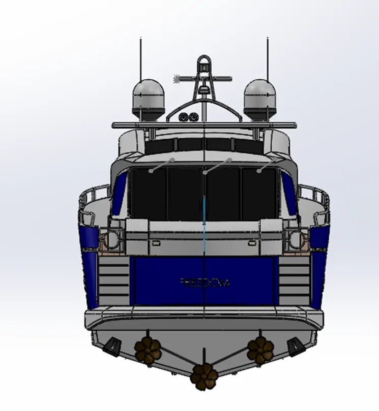
All the parts are inserted one by one in the assembly. The parts were inserted randomly in the assembly environment and given standard mates by taking the hull as reference.
Front View:
Side View:
Back View:
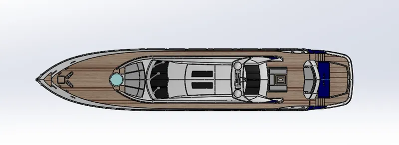
Top View:
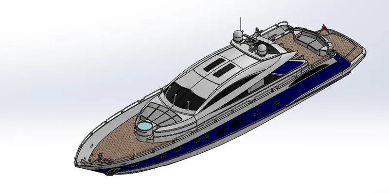
Isometric View:
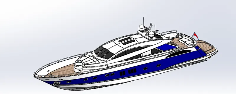
Camera View:
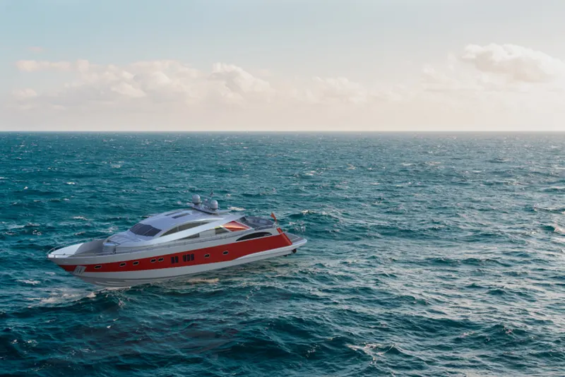
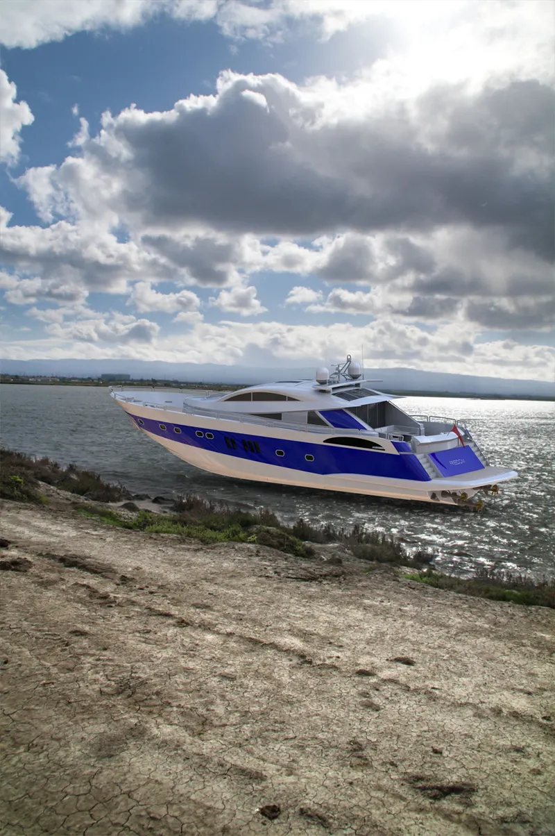
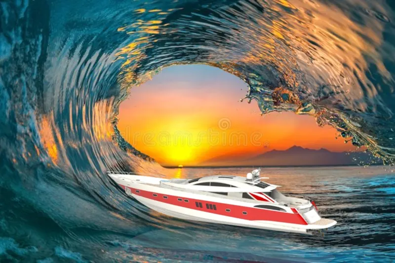
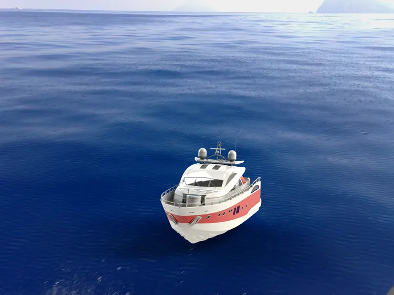
Photorealistic Rendering:
Rendering or image synthesis is the process of generating a photorealistic or non-photorealistic image from a 2D or 3D model by means of computer program. The resulting image is referred to as the render.
It can be done in two ways in SolidWorks. These are:
- Photo view 360
- SolidWorks Visualize
Conclusion:
- All the exterior parts of the yatch are modelled under Solidworks part modelling.
- All the parts are inserted in the assembly environment and the yatch is successfully completed.
- The photo-realistic image is successfully rendered with the use of the Photoview 360 & Solidworks visualize.