Aston Martin ONE-77 Challenge-11 (Project) Final Assembly
SURFACE MODELLING OF ASTON MARTIN ONE-77 USING SOLIDWORKS
OBJECTIVE:
The main objective of this project is to surface model all the parts of the Aston Martin One-77 and assemble and create it for Photo-Realistic Rendering.
INTRODUCTION:
The Aston Martin One-77 is a two-door, two-seater flagship sports car built by the British car manufacturer Aston Martin. The car was first shown at the 2008 Paris Motor Show, although it remained mostly covered by a "Savile Row tailored skirt" throughout the show. It was revealed in full at the 2009 Geneva Motor Show, and deliveries began in 2011.
Specifications of Aston Martin One-77
Length 4601mm
Width 2204mm
Height 1222mm
ARAI Mileage 6.0kmpl
City Mileage 4.0kmpl
Fuel Type Petrol
Engine Displacement 7312cc
No: of cylinders 12
Max power 510bhp@6500rpm
Max Torque 570Nm@5750rpm
Seating Capacity 2
Transmission Type Automatic
Fuel Capacity 98
Body Type Couple
In this course, we learn the techniques of surface modeling in Solidworks. We use blueprints to create the outer sketch of Aston Martin's car and then we use surface and solid modeling techniques. Then the surface and solid modeling parts are assembled in an assembly workbench and rendered as the final output.
Design Approach:
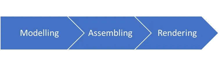
Design Methodology:
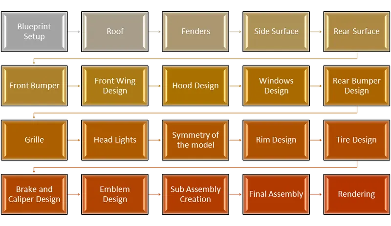
Surface Modelling:
Surface modeling is an alternative to solid-body modeling. Essentially, it’s just another tab at the top of the SOLIDWORKS User Interface. It is an important tool to have in your box because it not only makes modeling easier, it sometimes makes modeling possible. In other words, there’s some geometry that is impossible to create without using surface features. The SOLIDWORKS surface body creation process is very similar to its solid body creation. We’ll look at how to create simple extruded, revolved, and planar surfaces. Surface bodies don’t have a thickness and thus can also be used as reference geometry. This technique comes in handy especially when creating complicated geometries.
Commands used in Modelling
Features Commands
- Extruded Boss/Base: One of the oldest commands in the SOLIDWORKS software is the boss/base extrude command. An Extruded Boss/Base feature will allow you to take a 2D sketch and add thickness to it in the 3D.
- Extruded Cut: Extrude tool is used to extend a sketched profile in one or two directions as either a thin feature or a solid feature. An extrude operation can either add material to a part (in a base or boss) or remove material from a part.
- Split: Split tool projects an entity (sketch, solid, surface, face, plane, or surface spline) to surfaces, or curved or planar faces. It divides a selected face into multiple separate faces. You can split curves on multiple bodies with one command.
- Dome: The software calculates the distance using the radius of the arc as a basis for the dome. It creates a dome that is tangent to the adjacent cylindrical or conical face.
- Pierce Relationships: A pierce relationship is required to ensure that two entities from different axis collide or cross paths – the center point of entities can be selected to move the sketch entity to a mutual position. To apply a pierce relation a line and a sketch point are required.
- Projected Curve: You can create multiple closed or open-contour projected curves from a single sketch. You can also use 3D sketches as input for the Projected Curve tool. The Projected Curve tool does not support projections of intersecting curves. You can project curves from 2D and 3D sketches, onto faces and planes.
- Composite Curve: You can create composite curves by combining curves, sketch geometry, and model edges into a single curve. Use a composite curve as a guide curve when creating a loft or a sweep. To create a composite curve: Click Composite Curve on the Curves toolbar, or click Insert, Curve, Composite.
- Wireframe: Displays all the edges of the model. To display the model in wireframe.
Surface Commands
- Lofted Surface: Used to construct a B-spline parametric surface that is transformed between section elements (lines, line strings, arcs, ellipses, complex chains, complex shapes, B-spline curves, or the edges of a surface).
- Boundary Surface: The boundary surface feature lets you create surfaces that can be tangent or curvature continuous in both directions (all sides of the surface). In most cases, this delivers a higher quality result than the loft tool.
- Extruded Surface: You can select either a surface or the face of a solid body. You can also preselect the 3D faces to extrude before clicking Insert > Surface > Extrude. Select other faces to define the extrude as required. You can select faces that are not touching when you create a surface extrude in a given direction.
- Revolved Surface: Revolves add or remove material by revolving one or more profiles around a centerline. You can create revolved boss/bases, revolved cuts, or revolved surfaces. The revolving feature can be a solid, a thin feature, or a surface.
- Swept Surface: Create planes for sketching the sweep profile, sweep path, and if necessary, the guide curves. Sketch the sweep profile and path on the planes that you created. You can also sketch the sweep path on a model face or use a model edge for the path.
- Ruled Surface: The Ruled Surface command creates surfaces that extend out in a specified direction from selected edges.
- Filled Surface: The Filled Surface feature constructs a surface patch with any number of sides, within a boundary defined by existing model edges, sketches, or curves, including composite curves. You can use this feature to construct a surface to fill a gap in a model.
- Trim Surface: You can also use a surface in conjunction with additional surfaces, as mutual trim tools. Trim surface includes the following options: To trim a surface: Create two or more surfaces that intersect at one or more points or create a surface that intersects with a plane or has a sketch on its face.
- Knit Surface: Use the Knit Surface tool to combine two or more faces and surfaces into one. Note the following about knit surfaces: Edges of the surfaces must be adjacent and not overlapping. Surfaces do not need to be on the same plane.
- Move/Copy Surfaces: Moves or copy about a plane or sketch.
- Offset Surface: The Offset Surface tool creates a new surface body from an existing set of faces. The faces may be solid or surface faces. To create an offset surface: Click Offset Surface (Surfaces toolbar) or Insert > Surface > Offset.
- Extend Surface: You can extend a surface by selecting an edge, multiple edges, or a face. To extend a surface: Click Extended Surface (Surfaces toolbar) or Insert > Surface > Extend. In the Property Manager, under Edges/Faces to Extend, select one or more edges or faces in the graphics area for Selected Face/Edges.
- Mirror Surface: Creates a copy of a feature, (or multiple features), mirrored about a face or a plane. You can select the feature or you can select the faces that comprise the feature. Bodies to Mirror. Select a body in a single model or multi-body part to create a mirror entity.
- Reference Plane: The most common type of reference plane is an offset plane. To create an offset plane, select the Reference Geometry drop down on the Command Manager and choose the Plane option. Once the option to create a plane is open, select a face or another plane and set a distance for the offset.
- Fillet: Fillet/Round creates a rounded internal or external face on the part. You can fillet all edges of a face, selected sets of faces, selected edges, or edge loops.
- Split Line: The Split Line tool projects an entity (sketch, solid, surface, face, plane, or surface spline) to surfaces, or curved or planar faces. It divides a selected face into multiple separate faces. You can split curves on multiple bodies with one command.
Part Modelling Description
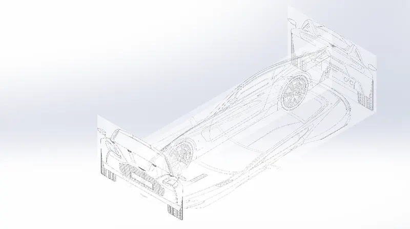
1. Blueprint Setup:
There are four different views (Front, Top, Side & Back) used in the blueprint setup. By using the Sketch Picture option images are inserted and the required dimensions are given to the images.
2. Roof
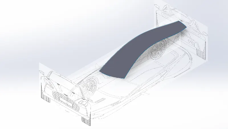
An automobile roof or car top is the portion of an automobile that sits above the passenger compartment, protecting the vehicle occupants from sun, wind, rain, and other external elements.
Tools Used:
- Sketch Tools
- Line
- Spline
- Surface Tools
- Boundary Surface
- Trim Surface
- Featured Tools
- Projected Curve
- Mirror
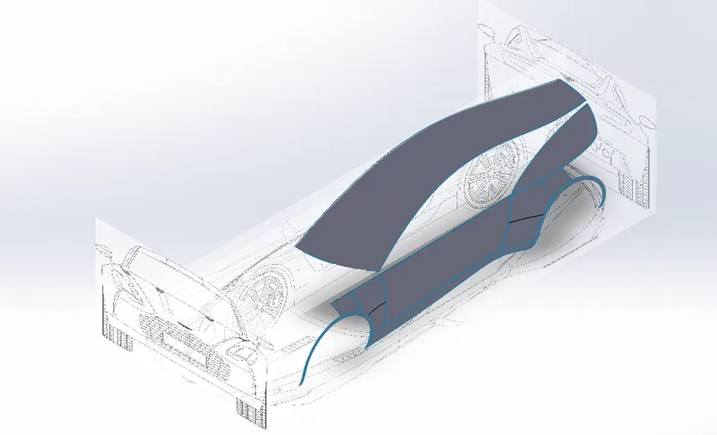
3. Fenders
A fender is the curved portion of the car's body that sits over and houses the wheels. The purpose of a fender is pretty simple. Its purpose is to keep mud, rocks, and other road debris from being thrown around by the tires. In other words, the fender is a housing for the wheels that keeps road debris contained. If there was nothing covering the wheels, all kinds of debris would be kicked up by the rotating tires. It not only protects your car from sustaining damage from road debris but it prevents this debris from being thrown up at other vehicles on the road. This is why vehicles with large, oversized tires are often required by law to install fender flares.
Tools Used:
- Sketch Tools
- Line
- Spline
- Circle
- Offset Entities
- Convert Entities
- Surface Tools
- Surface Trim
- Surface Extrude
- Boundary Surface
- Surface Fill
- Surface Knit
- Featured Tools
- Projected Curve
- Reference Plane
- Trim
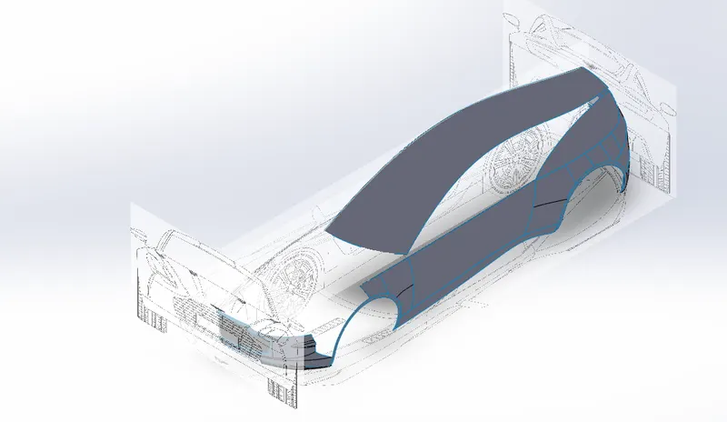
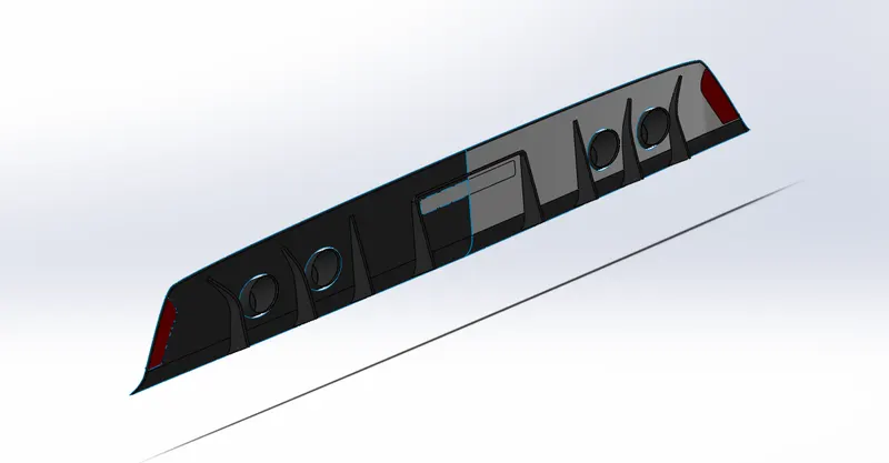
4. Front And Rear Bumpers
A bumper is a structure attached to or integrated with the front and rear ends of a motor vehicle, to absorb impact in a minor collision, ideally minimizing repair costs. Stiff metal bumpers appeared on automobiles as early as 1904 that had a mainly ornamental function. Numerous developments, improvements in materials and technologies, as well as a greater focus on functionality for protecting vehicle components and improving safety have changed bumpers over the years. Bumpers ideally minimize height mismatches between vehicles and protect pedestrians from injury. Regulatory measures have been enacted to reduce vehicle repair costs and, more recently, impact on pedestrians.
Tools Used:
- Sketch Tools
- Spline Line
- Line
- Circle
- Offset Entities
- Convert Entities
- 3D Sketch
- Surface Tools
- Surface trim
- Surface Extrude
- Boundary Surface
- Surface Fill
- Surface Knit
- Ruled Surface
- Offset Surface
- Surface Extend
- Featured Tools
- Projected Curve
- Reference Plane
- Trim
- Extrude Boss
- Extrude Cut
- Move/Copy
- Mirror
- Appearance
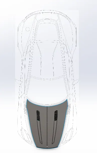
5. Hood
A car hood also referred to as a bonnet in some other countries is the hinged cover that rests over the engine of a front-engine vehicle. Its purpose is to provide access to the engine for repair and maintenance. A concealed latch is typically used to hold down the hood.
Tools Used:
- Sketch Tools
- Spline Line
- Line
- Circle
- Offset Entities
- Convert Entities
- 3D Sketch
- Surface Tools
- Surface trim
- Surface Extrude
- Boundary Surface
- Surface Fill
- Surface Knit
- Ruled Surface
- Offset Surface
- Surface Extend
- Move/copy body
- Cut with surface
- Featured Tools
- Projected Curve
- Reference Plane
- Trim
- Split
- Extrude Cut
- Combine
- Linear Pattern
- Mirror
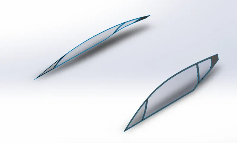
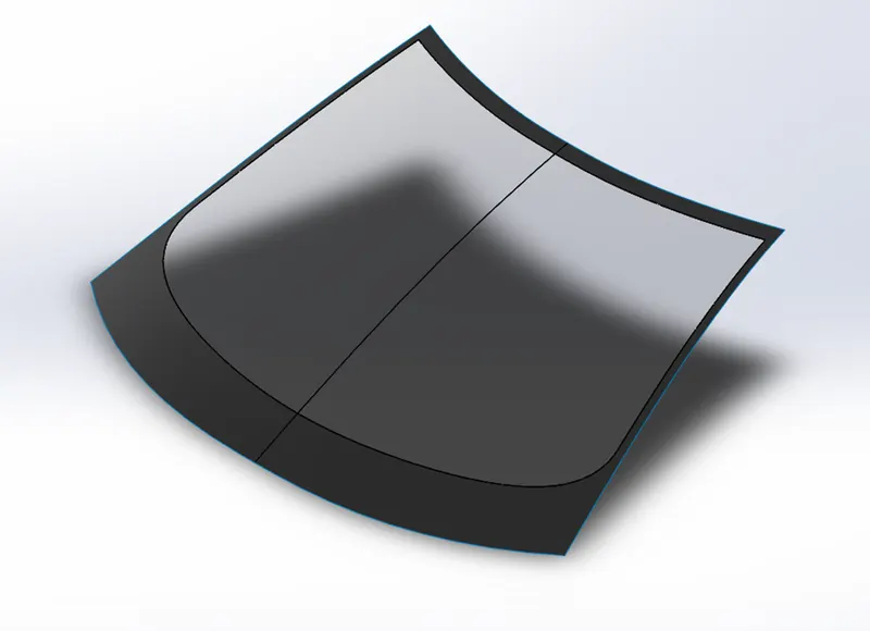
6. Windows and Windshields
The windshield or windscreen of a car is the front window, which provides visibility while protecting occupants from the elements. Modern windshields are generally made of laminated safety glass, a type of treated glass, which consists of, typically, two curved sheets of glass with a plastic layer laminated between them for safety, and bonded into the window frame. Windshields protect the vehicle's occupants from wind and flying debris such as dust, insects, and rocks, and provide an aerodynamically formed window towards the front. UV coating may b applied to screen out harmful ultraviolet radiation. However, this is usually unnecessary since most auto windshields are made from laminated safety glass.
Tools Used:
- Sketch Tools
- Spline Line
- Line
- Circle
- Offset Entities
- Convert Entities
- 3D Sketch
- Surface Tools
- Surface trim
- Surface Extrude
- Boundary Surface
- Surface Fill
- Surface Knit
- Ruled Surface
- Offset Surface
- Surface Extend
- Move/copy body
- Cut with surface
- Featured Tools
- Projected Curve
- Reference Plane
- Trim
- Split
- Extrude Cut
- Combine
- Linear Pattern
- Mirror
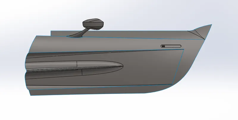
7. Doors
It is a type of door opening, typically hinged on its front edge, but sometimes attached by other mechanisms such as tracks, for entering and exiting a vehicle. Doors most often integrate side windows for visibility from inside the car and can be locked to secure the vehicle.
Tools Used:
- Sketch Tools
- Spline Line
- Line
- Circle
- Offset Entities
- Convert Entities
- 3D Sketch
- Surface Tools
- Surface trim
- Surface Extrude
- Boundary Surface
- Surface Fill
- Surface Knit
- Ruled Surface
- Offset Surface
- Surface Extend
- Move/copy body
- Cut with surface
- Featured Tools
- Projected Curve
- Reference Plane
- Trim
- Split
- Extrude Cut
- Combine
- Linear Pattern
- Mirror
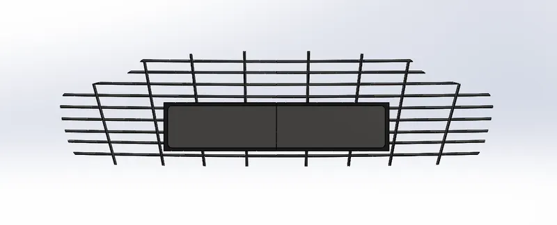
8. Grille
A grille covers an opening in the body of a vehicle to allow air to enter or exit. Most vehicles feature a grille at the front of the vehicle to protect the radiator and engine. Merriam-Webster describes grilles as "a grating forming a barrier or screen; especially: an ornamental one at the front end of an automobile." The word 'grille' is commonly misspelled as 'grill' which instead refers to the cooking method. Other common grille locations include below the front bumper, in front of the wheels (to cool the brakes), in the cowl for cabin ventilation, or on the rear deck lid (in rear engine vehicles). Grilles evolved from previously installed gravel shields that were designed to protect exposed radiators typically used on cars until the early 1930s.
Tools Used:
- Sketch Tools
- Spline Line
- Line
- Circle
- Offset Entities
- Convert Entities
- Surface Tools
- Surface Knit
- Offset Surface
- Surface Extend
- Move/copy body
- Featured Tools
- Trim
- Split
- Extrude Cut
- Combine
- Extrude Boss/Base
9. Lights
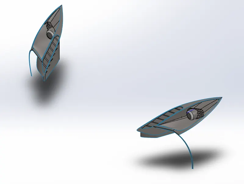
It consists of lighting and signaling devices mounted or integrated at the front, rear, sides, and in some cases the top of a motor vehicle. They illuminate the roadway ahead for the driver and increase the vehicle's visibility, allowing other drivers and pedestrians to see its presence, position, size, and direction of travel, and its driver's intentions.
Tools Used:
- Sketch Tools
- Spline Line
- Line
- Circle
- Offset Entities
- Convert Entities
- 3D Sketch
- Surface Tools
- Surface trim
- Surface Extrude
- Boundary Surface
- Surface Fill
- Surface Knit
- Ruled Surface
- Offset Surface
- Surface Extend
- Move/copy body
- Cut with surface
- Thicken
- Featured Tools
- Projected Curve
- Reference Plane
- Trim
- Split
- Extrude Cut
- Combine
- Linear Pattern
- Mirror
- Revolve
- Extrude Boss/Base
10. Front and Rear Wheel
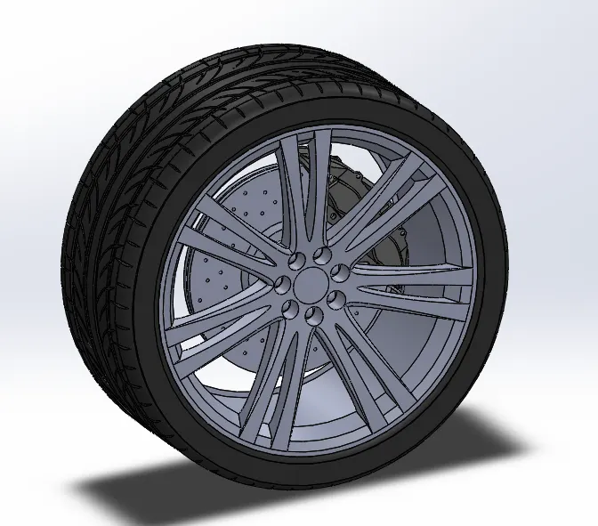
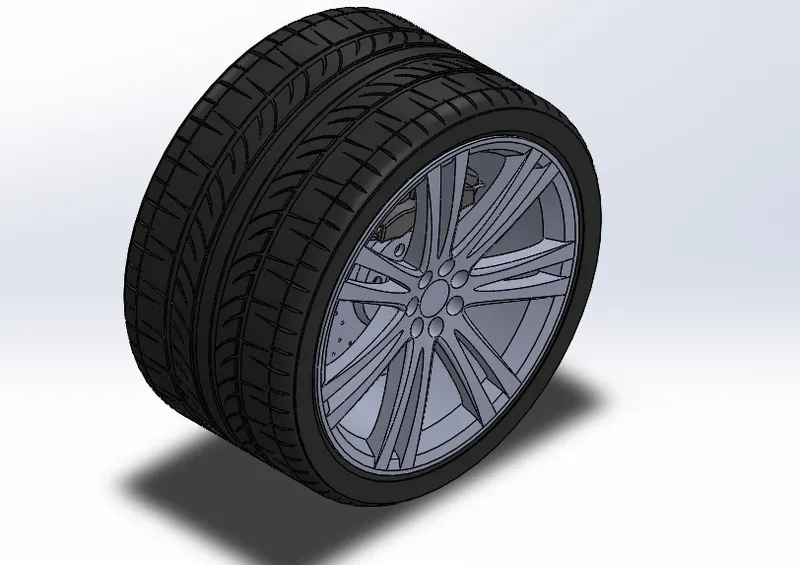
If a vehicle features front-wheel drive (FWD), the transmission transfers power from the engine to the front wheels. A great thing about FWD is that it’s cheaper to design and make than other drives, which means the vehicle may be less expensive for consumers. Most of the time, front-wheel-drive cars get better gas mileage because the weight of the drivetrain is less than that of a rear-wheel vehicle. FWD vehicles also get better traction because the weight of the engine and transmission is over the front wheels. Generally speaking, good traction in snow and rain makes your drive safer than if you were in a vehicle with rear-wheel drive (RWD). The downside of an FWD vehicle is that the handling suffers somewhat. While traction is good, handling the vehicle around corners and curves isn’t as strong as an RWD car, especially at faster speeds. If you do a lot of driving on winding roads, you’ll likely notice a difference between the two different types. The FWD won’t be as responsive or nimble on the road as an RWD. Rear-wheel drive vehicles are better for towing because the front wheels have better steering without a ton of weight on them. Plus, with the power transfer and the tongue weight of the trailer, the rear of the vehicle squats, which gives the rear wheels more traction. If you get stuck, adding weight over the rear wheels may help.
Tools Used:
- Sketch Tools
- 3-point arc
- Spline
- Circle
- Trim
- Rectangle
- Fillet
- Featured Tools
- Revolve
- Extruded Boss/Base
- Circular Pattern
- Chamfer
- Revolve cut
- Appearance
11. Emblem
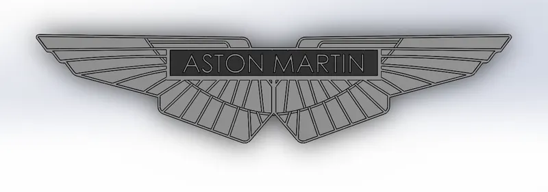
The part was entirely made with solid modeling.
Tools Used:
- Featured Tools:
- Extruded Boss/Base
- Extrude Cut
- Mirror
- Combine
Assembly
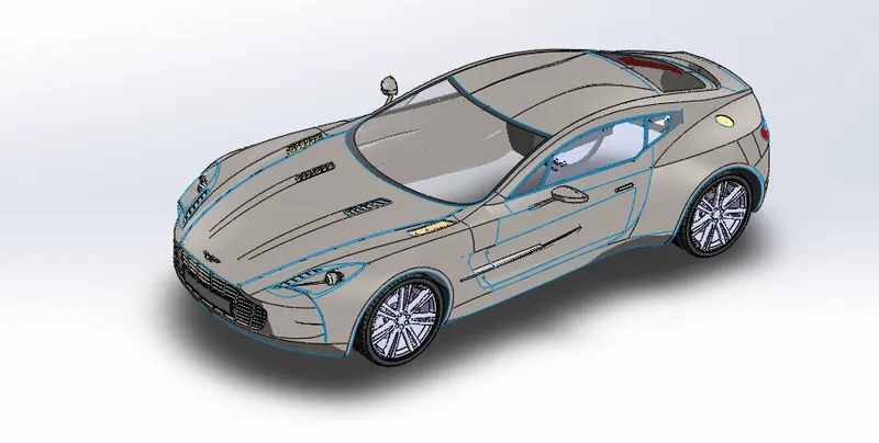
After making all the parts the most important part of assembling the entire car into a single file begins. To start with bringing the body first and using its plane and geometry as a base for the entire solid assembly, the second part we bring in is the doors. The planes of doors made coincident mate with the corresponding planes of the body. After that, we bring the hood, windows, front and rear windshields, grille, and rear bumper made coincident mates with the planes of the body. For the front and rear wheels, we use distance mates of 93.3mm for the front wheel and 92.2mm for the back wheels from the front plane. Finally, the Aston Martin emblem is fixed with the body.
Photorealistic Rendering
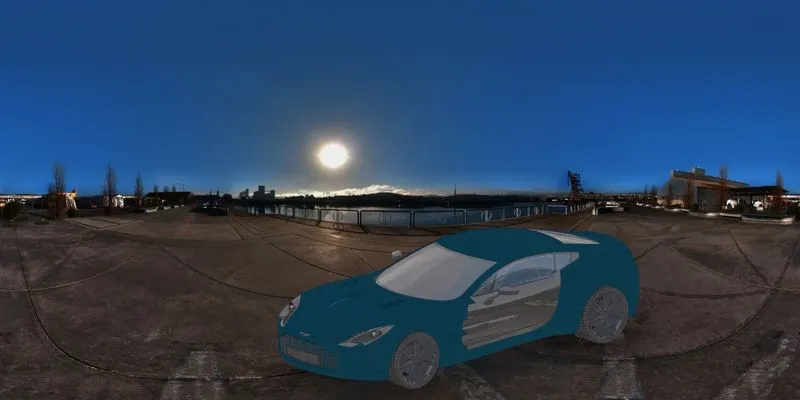
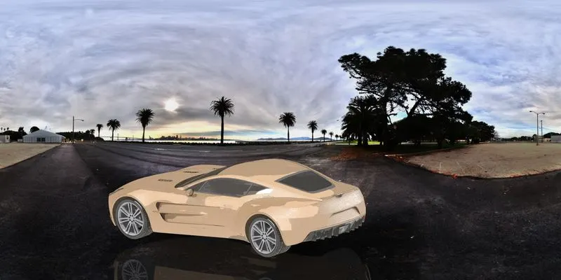
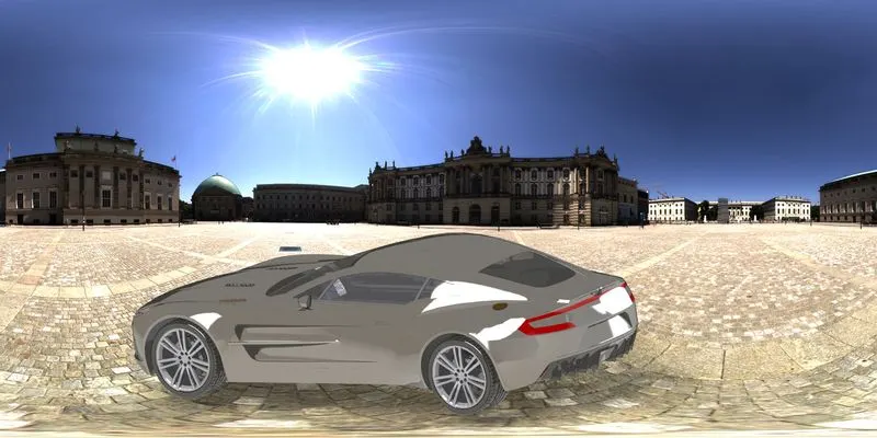
Rendering or image synthesis is the process of generating a photorealistic or non-photorealistic image from a 2D or 3D model by means of computer program. The resulting image is referred to as the render.
It can be done in two ways in SolidWorks. These are:
- Photo view 360
- SolidWorks Visualize
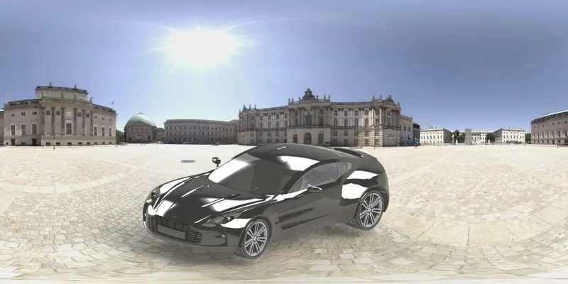
Conclusion
In this project, various models/parts were created using many commands and areas like Surface modeling and combining all the models by using the assembly feature available in SolidWorks. Rendering was done to come out with a realistic effect on the assembly that we have modeled using Photo view 360 and SolidWorks Visualize.