Boeing-747 _ Final_Project
MODELLING OF BOEING 747-8 USING SOLIDWORKS
OBJECTIVE:
The main objective of this project is to sketch and model a Boeing 747-8 aircraft using SolidWorks in a part modeling and surface modeling environment and then assemble the individual parts using SolidWorks Assembly Environment.
PARTS MODELED IN BOEING 747-8:
- Fuselage
- Belly Fairing
- Nose Cone
- Pitot Tubes
- Cockpit Windows
- Windshield Wipers
- Passenger Windows
- Doors and Hatches
- Lights and Antennas
- Auxiliary Power Unit
- Horizontal Stabilizer
- Vertical Stabilizer
- Static Discharge Tubes
- Wings
- Flaps and Ailerons
- Flap Track Fairings
- Landing Gear Axis
- Landing Gear Hatches Closed
- Landing Gear Hatches Open
- Wheel
- Nose Gear Base
- Nose Gear Suspension Arm
- Main Gear Base
- Main Gear Suspension Arm
- Engine
- Livery
ASSEMBLY MODELLED IN BOEING 747-8:
- Nose Gear Assembly
- Main Landing Gear Assembly
- Boeing 747-8 Assembly
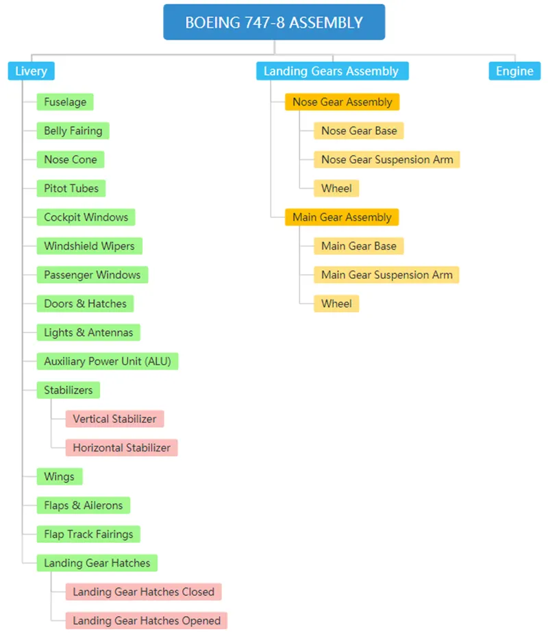
Fig: Assembly tree of Boeing 747-8
INTRODUCTION OF BOEING 747-8
The Boeing 747-8 is a wide-body airliner developed by Boeing Commercial Airplanes, the largest variant of the 747. After introducing the 747-400, Boeing considered larger 747 versions as alternatives to Airbus's proposed Airbus A3XX. The stretched 747 Advanced was launched as the 747-8 on November 14, 2005, for a market forecast of 300 aircraft. The first 747-8F Freighter performed its maiden flight on February 8, 2010, and the passenger 747-8I Intercontinental followed suit on March 20, 2011. The cargo version was first delivered in October 2011 and the airliner began commercial service in June 2012.
Its fuselage is stretched by 18 ft (5.6 m) to 250 ft (76.3 m), making it the longest airliner until the 777X-9 which first flew in 2020.
The airliner version can carry 467 passengers in a typical three-class configuration over 7,790 nmi (14,430 km) at a cruise speed of 0.86 (914 km/hr).
SPECIFICATIONS OF BOEING 747-8
|
Length |
76300 mm |
|
Wingspan |
68400 mm |
|
Height |
19400 mm |
|
Maximum take-off weight |
440000 kg |
|
Maximum landing weight |
306200 kg |
|
Operating empty weight |
211900 kg |
|
Maximum zero fuel weight |
288000 kg |
|
Maximum payload |
76300 kg |
|
Standard fuel capacity |
243400 kg |
|
Range with max payload |
14300 km |
|
Engines |
GE GEnx-2B, |
1. Blueprint Setup
There are three different views (Front, Top & Side) used in the blueprint setup. By using the Sketch Picture option images are inserted and the required dimensions are given to the images.
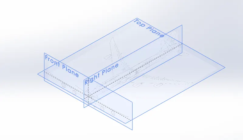
Fig: Blueprint Setup
2. Fuselage
The fuselage, or body of the airplane, is a long hollow tube that holds all the pieces of an airplane together. The fuselage is hollow to reduce weight. As with most other parts of the airplane, the shape of the fuselage is normally determined by the mission of the aircraft. A supersonic fighter plane has a very slender, streamlined fuselage to reduce the drag associated with high-speed flight. An airliner has a wider fuselage to carry the maximum number of passengers. On an airliner, the pilots sit in a cockpit at the front of the fuselage. Passengers and cargo are carried in the rear of the fuselage and the fuel is usually stored in the wings. For a fighter plane, the cockpit is normally on top of the fuselage, weapons are carried on the wings, and the engines and fuel are placed at the rear of the fuselage.
Initially required sketches of the fuselage are created in SolidWorks and then by using the Surface loft command half of the fuselage is modeled. The other half is created by using the Mirror command. To convert the following Surface body to a Solid body the Knit command is used.
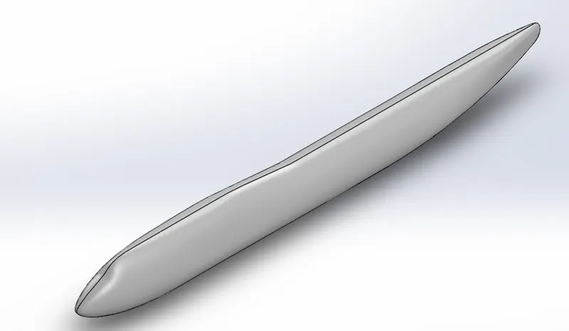
Fig: Fuselage
3. Belly Fairing
Belly Fairing also called a "ventral fairing", is a structure whose primary function is to produce a smooth outline and reduce drag. These structures are covers for gaps and spaces between parts of an aircraft to reduce form drag and interference drag. It is located on the underside of the fuselage between the main wings. It can also cover additional cargo storage or fuel tanks and gives space to Body Landing Gears.
Belly Fairing is modeled using Boss Extrude, Fillet, Mirror, and Combine command.
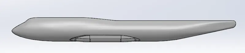
Fig: Belly Fairing
4. Nose Cone
Found at the foremost point of an aircraft, a nose cone must be aerodynamic to reduce drag on a plane. On most commercial and military aircraft, the nose cone also houses radar and other instruments that might be used to detect meteorological phenomena, track enemy aircraft, or transmit communication signals. There are different shapes of the nose cone.
- General dimensions.
- Conic
- Bi-conic.
- Tangent ogive.
- Secant ogive.
- Elliptical
- Parabolic
- Power series
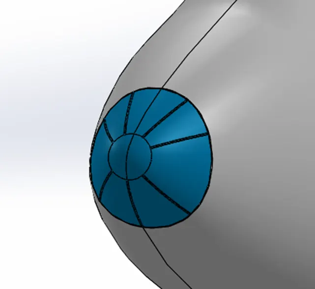
Fig: Nose Cone
5. Pitot Tubes
Pitot tubes are also called “pitot probes”. It is a flow measurement device used to measure fluid flow velocity. It is widely used to determine the speed of aircraft. The Pitot tube measures air velocity directly by means of a pressure transducer which generates an electrical signal which is proportional to the difference between the pressure generated by the total pressure and the still air. It is the pressure-sensitive instrument used to measure
- Aircraft’s airspeed
- Mach number
- Altitude
- Altitude trend
There are four pitot tubes available in Boeing 747-8 aircraft. Two pitot tubes are placed on the right side of the aircraft and the other two on the other side of the aircraft. It is modeled by using Extrude Boss/Base, Fillet, and Revolve command.
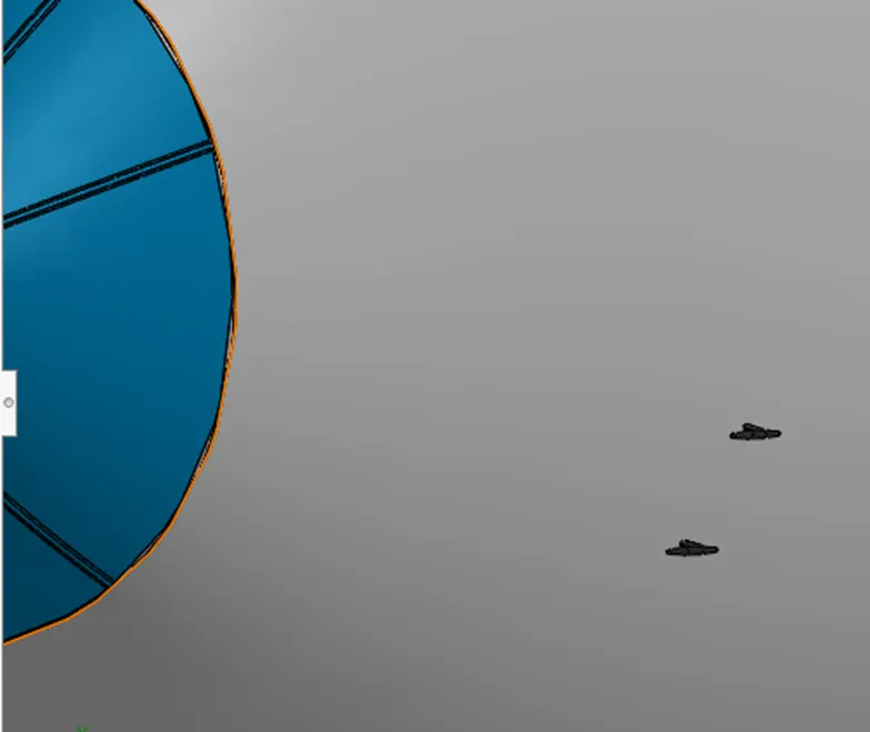
Fig: Pitot Tubes
6. Cockpit Window
A cockpit or flight deck is the area, usually near the front of an aircraft or spacecraft, from which a pilot controls the aircraft. The cockpit of an aircraft contains flight instruments on an instrument panel, and the controls that enable the pilot to fly the aircraft. In most airliners, a door separates the cockpit from the aircraft cabin.
The two main functions of the cockpit are to provide the pilot with a good angle and to make all control mechanisms accessible to them. Planes are also designed based on the same principle of any vehicle.
It is modeled by using Extruded Boss/Base, Fillet, Thicken, Offset Surface commands.
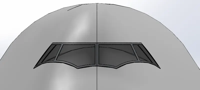
Fig: Cockpit Window
7. Windshield Wipers
Windshield wiper or windscreen wiper is a system used to remove rain, debris, snow, and ice from an aircraft front window, so the pilot can access a better view. It plays a very important role during the takeoff and landing, as well as at the time of flight. The two wipers operate independently, giving pilot and co-pilot control over their windshield. Some planes have windshields that repel water. They also use electric defrosters to get rid of any fog or ice in windshield.
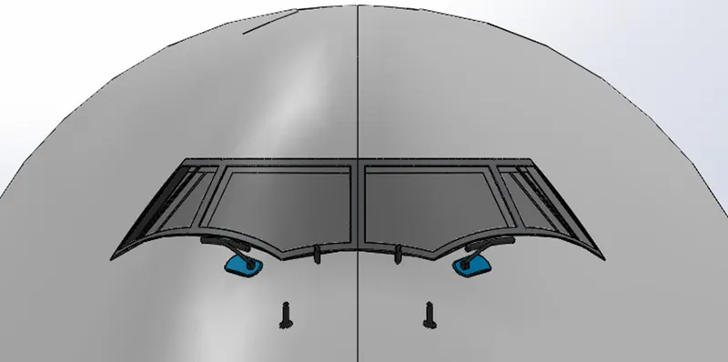
Fig: Windshield Wipers
8. Passenger Windows
A cabin window consists of three panes,
- An outer pane flush with the outside fuselage
- An inner pane- Which has a little hole in it.
- A thinner non-structural plastic pane called a scratch pane.
The aircraft cabin windows are not made of glass. It is made of “stretched acrylic”.
Boeing 747-8 aircraft has 250 passenger windows. The outer pane is 12mm thick and the inner pane 4mm thick. They are separated by a 6mm edge chamfer.
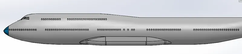
Fig: Passenger Windows
9. Doors and Hatches
There is a total of 6 doors on each side of Boeing 747-8. The cockpit escape hatch is placed above the cockpit. In case of emergency, pilots can escape through this hatch. There are 3 hatches available on the right side of fuselage. These hatches are available for the cargo compartment.
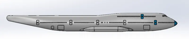
Fig: Doors and Hatches
10. Lights and Antennas
There are 2 lights and 3 antennas in the Boeing 747-8 mode. The lights are on the back side of the cockpit. Two antennas are in the top of the fuselage and one in the beneath of the fuselage.
The external lights on aircraft fall into two general categories. The first is navigation lights or beacons that are always illuminated while the aircraft is in operation. A second type includes takeoff and landing lights that are used to improve visibility when the plane is close to or on the ground.
Aircraft antennas can have many different shapes and sizes, which are largely determined by the manufacturer itself. Antennas, however, are formed more for their function than anything else, and their shape and placement are usually determined by their directional qualities and the frequencies they use to operate. Essentially, these antennas need to be certain shapes and placed in certain spots to operate correctly.
Different types of antennas are:
- Communication Antennas
- GPS Antennas
- Loran Antennas
- Loop Antennas
- Marker Beacon Antennas
- NAV Antennas
- Radio Antennas
- UHF Antennas
It is modeled by using Extruded Boss/Base, Revolve Boss/ Base, Fillet, and Move commands.
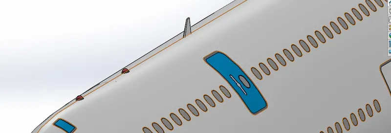
Fig: Lights and Antennas
11. Auxiliary Power Unit (APU)
An aircraft auxiliary power unit serves as an additional energy source normally used to start one of the main engines on an airliner or business jet. The APU is equipped with an extra electrical generator to create enough power to operate onboard lighting, galley electrics and cockpit avionics, usually while the aircraft is parked at the gate. Drawing bleed air from its own compressor, an APU also drives the environmental packs used to heat and cool the aircraft.
And most important, operating an APU negates the need to start one of the aircraft’s main engines while waiting for passengers to arrive, thereby saving on fuel and maintenance for a more expensive power plant.
In most cases, the APU is shut down before takeoff and reignited when the aircraft clears the runway after landing. While most of an APU’s active service life occurs as the aircraft sits on the ground, in some instances the APU is used as an emergency electrical power source while the aircraft is airborne.
The APU is a small turbine engine installed near the rear of the fuselage. But calling the APU an extra jet engine is not accurate because the turbine exhaust from the APU is vented overboard. A jet engine would be used to propel the aircraft forward.
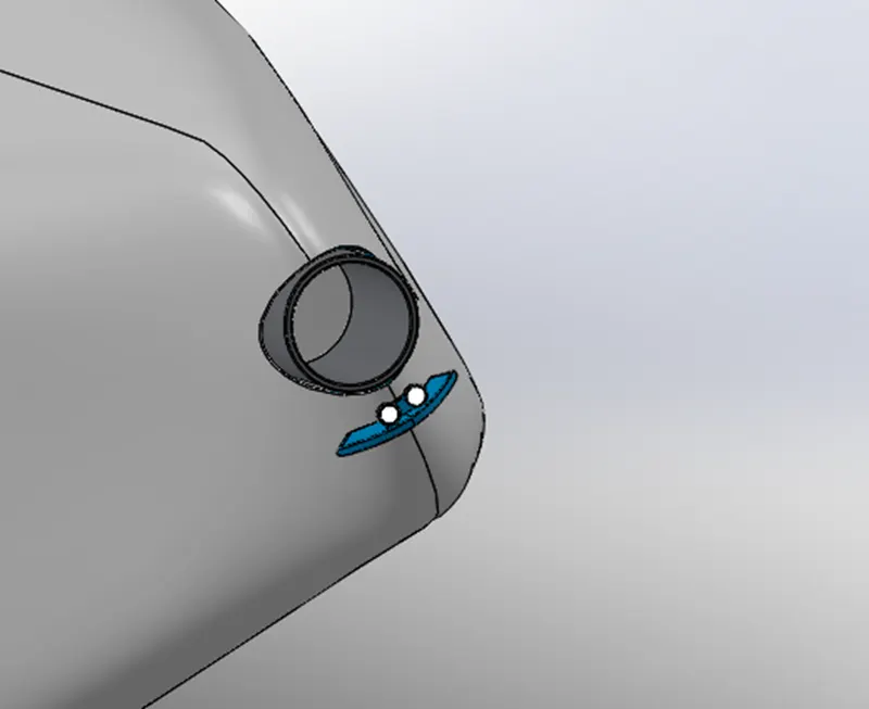
Fig: Auxiliary Power Unit (APU)
12. Vertical Stabilizer
A vertical stabilizer or tail fin is the static part of the vertical tail of an aircraft. The term is commonly applied to the assembly of both this fixed surface and one or more movable rudders hinged to it. Their role is to provide control, stability, and trim in yaw. The vertical tail is typically mounted on top of the rear fuselage, with the horizontal stabilizers mounted on the side of the fuselage.
Types of Vertical Stabilizer:
- Single Stabilizer
- Conventional Tail
- T- Tail
- Cruciform Tail
- Multiple Stabilizer
- Twin Tail
- H-Tail
- Twin Boom Tail
- Boom Mounted Inverted V
- Triple Tail
- V- Tail
- Winglet
- Ring Tail
- Y-Tail
- Inverted V- Tail
- Pelican Tail
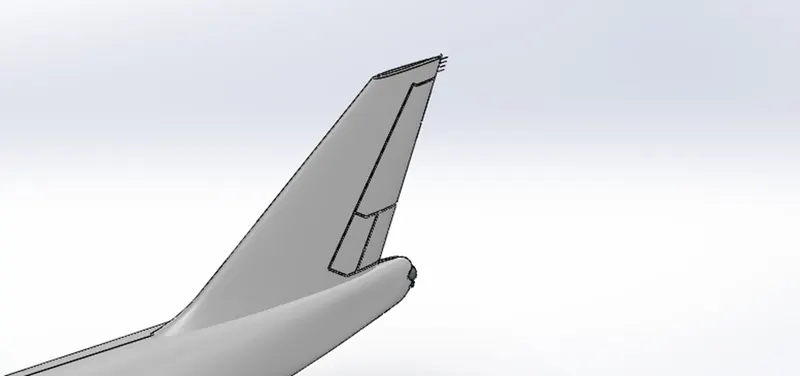
Fig: Vertical Stabilizer
13. Horizontal Stabilizer
Horizontal stabilizer located on the left and right sides of the airplane’s tail. It is designed to maintain the airplane’s trim. In works by creating an upwards force that balances the airplane, horizontally, during flight. As the airplane flies, its horizontal stabilizers will push the air upwards to prevent swings in trim.
Horizontal stabilizers are rather simple components that consist of small and thin pieces of material — typically the same material from which the fuselage is constructed. They essentially look like small wings on the sides of the tail. Both the left and right sides of an airplane’s tail will have a horizontal stabilizer. While horizontal stabilizers create a vertical force during flight, they extend horizontally from the sides of the tail.
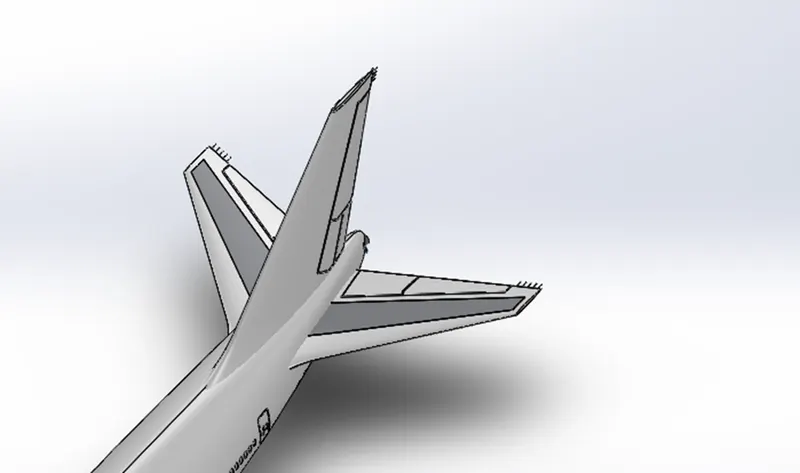
Fig: Horizontal Stabilizer
14. Wings
A wing is a type of fin that produces lift while moving through air or some other fluid. Accordingly, wings have streamlined cross-sections that are subject to aerodynamic forces and act as airfoils. A wing's aerodynamic efficiency is expressed as its lift-to-drag ratio. The lift a wing generates at a given speed and angle of attack can be one to two orders of magnitude greater than the total drag on the wing. A high lift-to-drag ratio requires a significantly smaller thrust to propel the wings through the air at sufficient lift.
In aeronautics, an airfoil helps lift a heavier-than-aircraft. When positioned above the fuselage (high wings), wings provide an unrestricted view below and good lateral stability. Parasol wings, placed on struts high above the fuselage of seaplanes, help keep the engine from water spray.
Mid wings, positioned in the middle of the fuselage, leave the airplane belly free of spars, with room for bombs or cargo. Placed below the fuselage, low wings reduce the height of the undercarriage and simplify engine maintenance.
15. Flaps and Ailerons
An Aileron is used to control the roll of an aircraft. Ailerons are found on the trailing edge of the wing, typically closer to the wingtip. Ailerons will move in opposite directions to each other, as one goes up, the other goes down.
Flaps are used to increase the amount of lift that a wing produces by increasing the camber and surface area of the wing. Typically, they are located near the root of the wing. Flaps on each wing are moved together, both extend and retract at the same rate.
Flaps are generally more complex depending on the type. The basic flaps will just pivot down from the lower edge of the wing. Modern airliners have a fowler flap which both pivots down and extend back from the lower edge of the wing.
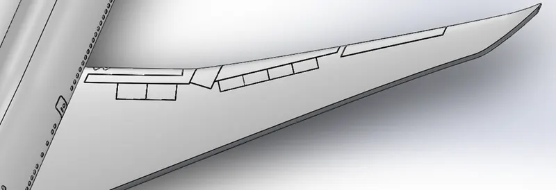
Fig: Wings, Flaps & Ailerons
16. Flap Track Fairings
Flap track fairing is a secondary structure whose function is to provide an aerodynamic cover and so reduce drag. Flaps are used to reduce take-off and landing distance. It is mounted under the trailing edge of the fixed-wing aircraft. Boeing 747-8 has a total of 8 flap track fairings, 4 on left and 4 on right.
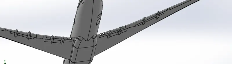
Fig: Flap Track Fairings
17. Landing Gear Hatches Closed and Open
A landing gear flap, more simply called a hatch, usually includes a panel attached to hinge arms. Generally, these hinge arms are articulated on the aircraft structure, around a pivot axis shifted inwardly of the landing gear with respect to the panel. Upon exit of the landing gear, the pivoting of the panel towards the outside of the fuselage is obtained by means of a connecting rod placed between the panel and the structure, inside the box of train. To preserve the aerodynamics of the fuselage, the arrangement of the pivot axis is made inside the train compartment. Also, for reasons of aerodynamics, the secondary hatches must have the smallest possible opening to allow the passage of the landing gear while preserving the aerodynamic continuity. Currently, each secondary hatch is connected to the train landing by a direct link. This direct link consists of a connecting rod fixed on the one hand, on the landing gear, for example on the landing gear leg or on the strut, and on the other hand, on the hatch. This rod allows a maneuver of the hatch directly according to the movements of the landing gear. Thus, when the landing gear is retracted, the very fact that the landing gear rises in the landing gearbox ensures the closure of the hatch. Meanwhile, during the landing gear output, this direct connection allows the opening of the door by pushing said hatch towards the outside of the fuselage. More specifically, during the output of the train, it rotates about an axis, causing a translational movement of the rod that pushes the hatch into its open position. Such a direct connection thus makes it possible to control at the same time the exit of the landing gear and the opening of the hatch.
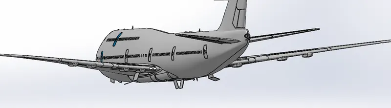
Fig: Landing Gear Hatch
18. Engine
An aircraft engine often referred to as an aero engine, is the power component of an aircraft propulsion system. Most aircraft engines are either piston engines or gas turbines, although a few have been rocket powered and in recent years many small UAVs have used electric motors. In commercial aviation, the major Western manufacturers of turbofan engines are Pratt & Whitney General Electric, Rolls-Royce, and CFM International.
All aircraft engines, which are also called gas turbines, work on the same principle. The engine sucks air in at the front with a fan. A compressor raises the pressure of the air. The compressor is made with many blades attached to a shaft. The blades spin at high speed and compress or squeeze the air. The compressed air is then sprayed with fuel and an electric spark lights the mixture. The burning gases expand and blast out through the nozzle, at the back of the engine. As the jets of gas shoot backward, the engine and the aircraft are thrust forward. As the hot air is going to the nozzle, it passes through another group of blades called the turbine. The turbine is attached to the same shaft as the compressor. Spinning the turbine causes the compressor to spin.
The engine selected for the aircraft is the GEnx-2B67, the General Electric next-generation engine. The design of the 747-8 aircraft engine is slightly modified variant of the GEnx engine developed for the Boeing 787 Dreamliner aircraft. The engine provides 66,500lb of thrust.
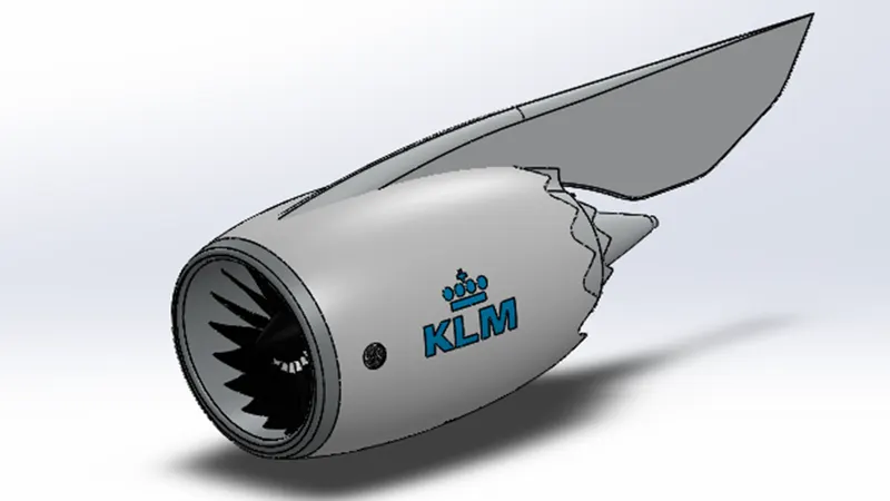
Fig: Engine
19. Livery
The aircraft liveries and logos of airlines are used to provide distinctive branding for corporate and commercial reasons. Often, they also combine symbols of national identity while being acceptable to an international market.
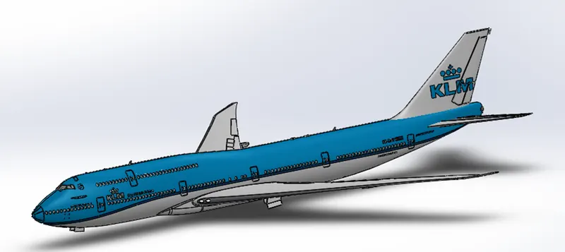
Fig: Livery
Sub-Assemblies:
1. Nose Gear Assembly
Nose gear assembly has parts like Nose Gear Base, Suspension Arms and Wheels. The parts are initially modeled, and the parts are inserted into the assembly environment and the sub-assembly is created for the Nose gear. In Boeing 747-8 one nose gear assembly is used. There are two wheels in the nose gear assembly.
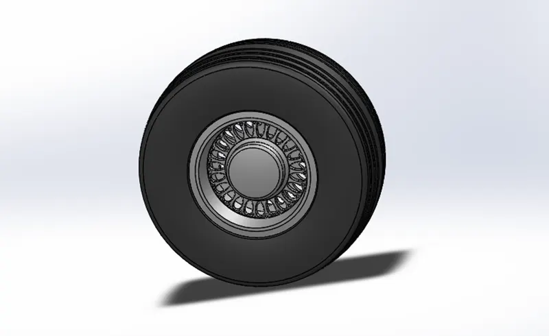
Fig: Wheel
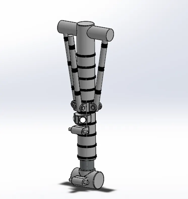
Fig: Nose Gear Base
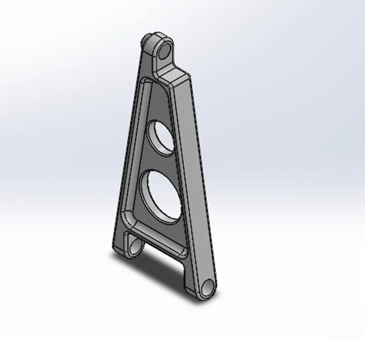
Fig: Nose Gear Suspension Arm
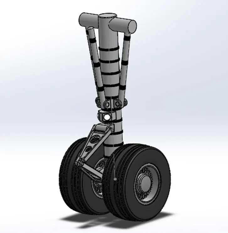
Fig: Nose Gear Assembly
2. Main Gear Assembly
The Main Gear Assembly consists of the main gear base, two main gear suspension arms, and four wheels.
The parts for the main gear assembly are created initially then the parts are inserted into the assembly environment and the Main Gear assembly is created.
There are four main landing gears available in the Boeing 747-8. Each landing gear consists of four wheels. All the main landing gears are in nearer to the rear side of the fuselage.
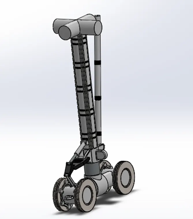
Fig: Main Gear Base
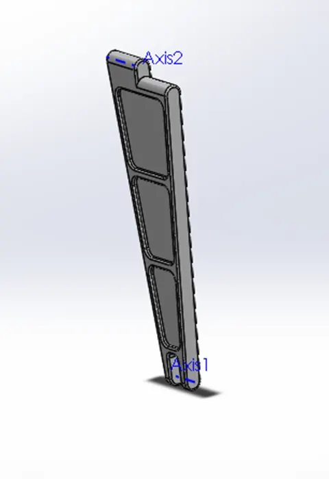
Fig: Main Gear Suspension Arm
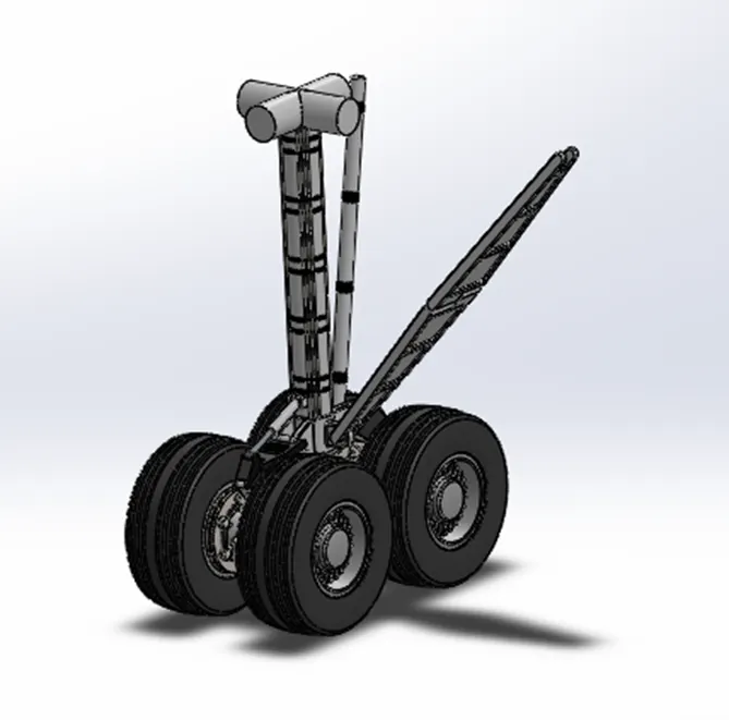
Fig: Main Gear Assembly
3. Boeing 747-8 Assembly
After completing the livery part, the main body is inserted into the assembly environment. Then the engine is inserted into the assembly.
The engine is assembled with the main body by applying the coincidence and distance mates between the engine and fuselage planes. Then by using the move/copy command other engines are created in the assembly.
The same steps are followed for the Nose Gear and Main Gear assembly. The mate conditions are created between the Main Gear, Nose Gear sub-assembly, and the Fuselage. Finally, the Boeing 747-8 is assembled.
There are different types of mates used in this project:
- Coincident Mates
- Distance Mates
- Concentric Mates
- Angular Mates
- Gear Mates
Gear mates play an important role in the movement of the mechanical components modeled in SolidWorks. This mate is applied to the nose and main landing gear so that it moves approximately in the desired location.
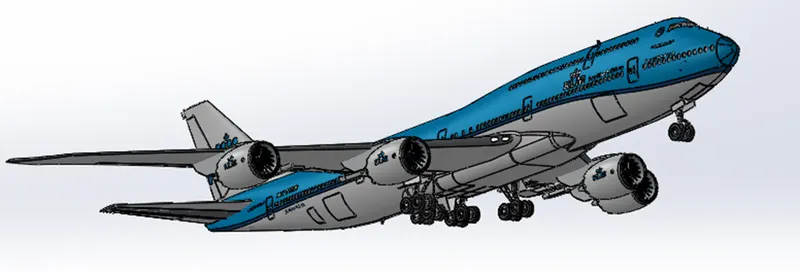
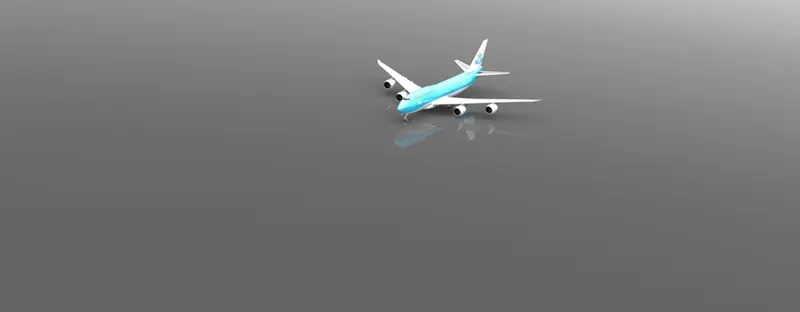
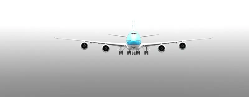
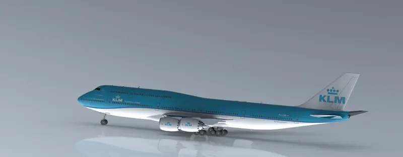
Fig: Boeing 747-8 Main Assembly
Rendering
Rendering or image synthesis is the process of generating a photorealistic or non-photorealistic image from a 2D or 3D model by means of a computer program. The resulting image is referred to as the render.
It can be done in two ways in SolidWorks. These are:
- Photoview 360
- SolidWorks Visualize
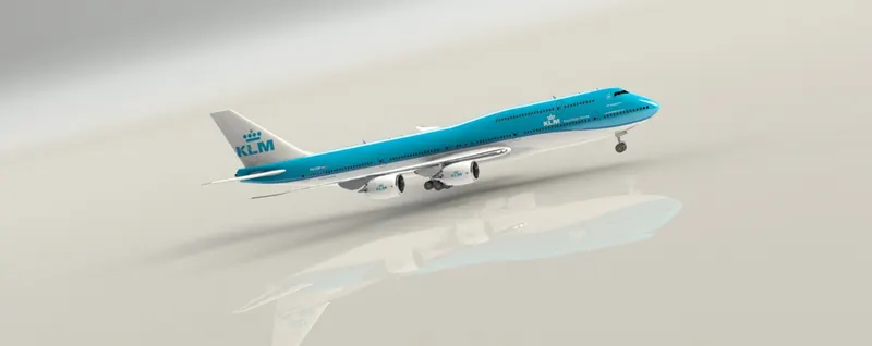
Some of the rendered BOEING 747-8 Final Assembly images are given below:
\
Conclusion:
In this project, various models/parts were created using many commands and areas like Surface, Solid modeling, and combining all the models by using assembly feature available in SolidWorks. Rendering was done to come out with a realistic effect on the assembly that we have modeled using Photoview 360 and SolidWorks Visualize.