Flow over an airfoil
1. Aim:
To model the flow over a NACA0017 airfoil and compare the lift and drag forces for the angle of attacks 0,2,4,6,8,10.
2. Introduction:
The NACA airfoils are airfoil shapes for aircraft wings developed by the National Advisory Committee for Aeronautics (NACA). The shape of the NACA airfoils is described using a series of digits following the word "NACA". The parameters in the numerical code can be entered into equations to precisely generate the cross-section of the airfoil and calculate its properties.
The NACA four-digit wing sections define the profile by:
- The first digit describes the maximum camber as a percentage of the chord.
-
The second digit describes the maximum camber distance from the airfoil leading edge in tenths of the chord.
-
The last two digits describe the maximum thickness of the airfoil as a percent of the chord.
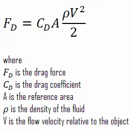
Drag Force
The resistance offered by a fluid, like air and water, is called the drag force or drag when an object moves through it. It acts in a direction opposite to the object’s motion. It is generated by the relative velocity between the solid object and the fluid. Whether the object or fluid is moving, drag occurs as long as there is a difference in their velocities. Because it is resistant to motion, drag tends to slow down the object. An effective way to reduce it is to alter the shape of the object and make it streamline.
Examples
- A car driving on a highway
- A ship sailing in the ocean
- A skydiver falling through the sky experiences drag after opening the parachute.
- A swimmer swimming in a pool
- A racing car speeding through a circuit
- An airplane flying through the air
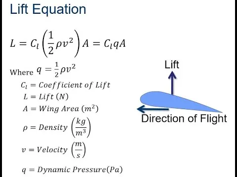
Lift Force
Lift is the force that directly opposes the weight of an airplane and holds the airplane in the air. Lift is generated by every part of the airplane, but most of the lift on a normal airliner is generated by the wings. Lift is a mechanical aerodynamic force produced by the motion of the airplane through the air. Because lift is a force, it is a vector quantity, having both a magnitude and a direction associated with it. Lift acts through the center of pressure of the object and is directed perpendicular to the flow direction. There are several factors that affect the magnitude of lift.
Examples:
The most common type of lift is that of a wing aircraft. But there are many common uses such as propellers on both aircraft and boats, rotors on helicopters, fan blades, sails on sailboats, and wind turbines
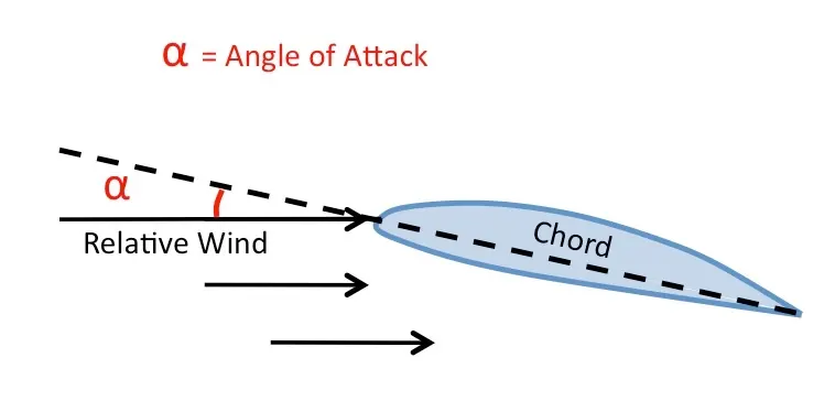
Angle of Attack:
The Angle of Attack is the angle at which relative wind meets an Aerofoil. It is the angle formed by the Chord of the aerofoil and the direction of the relative wind or the vector representing the relative motion between the aircraft and the atmosphere.
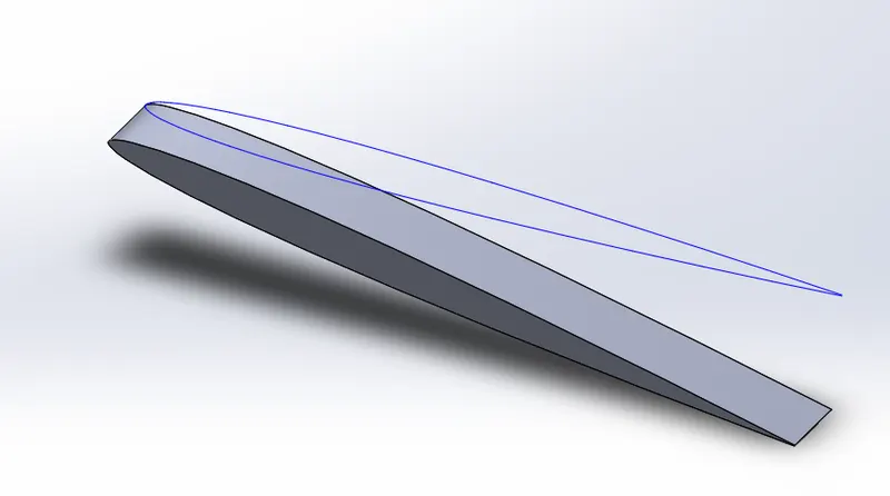
3. CAD Geometry:
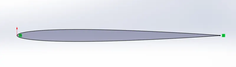
Initial Airfoil Geometry
Extruded Part
4. Flow Simulation
Parameters:
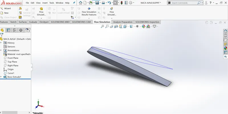
- External flow simulation
- Time-dependent study
- Pressure: 101325KPa
- Temperature: 293.2K
- Velocity along X-axis: 600m/s
- Medium: Air
Procedure:
- Input the airfoil curve from the NACA0017.txt fil (lnsert>Curves>Curves trough reference point.)
- Rotate the airfoil as per the needed angle of attack.
- Extrude the curve after converting the curve into a sketch.
- Activate the flow simulation plugin of SolidWorks in the add-ins tab.
- Select wizard and input respective details including medium as per parameters given above to set the
- Set the computational domain to 2D and set the domain in such a way that the simulation result is not affected.
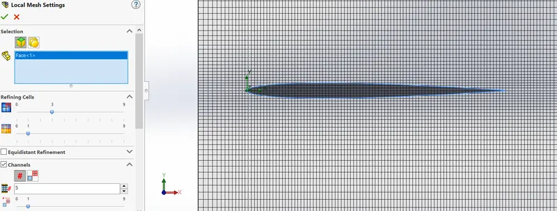
- Edit the definition of GlobalMesh and define the mesh into a more fine mesh
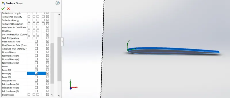
- Insert a local mesh on the surface of the airfoil for a more accurate
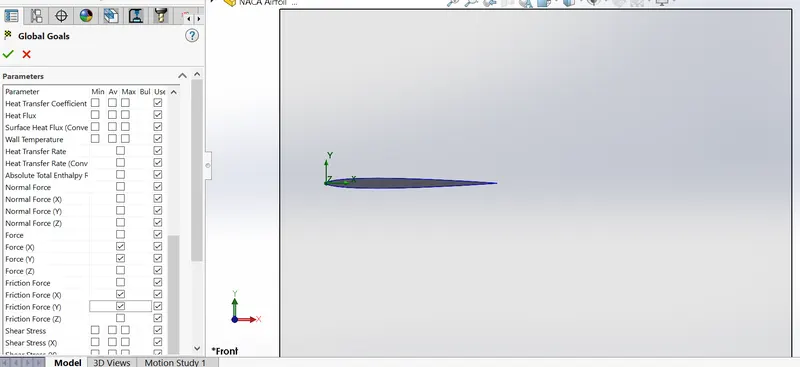
- Set surface goals (Forces on X and Y axis) to get drag and lift
- Run the simulation
- Plot a cut plot for pressure contour and velocity
- Insert goals from the result to get the drag and lift force results.
5. Results:
Here
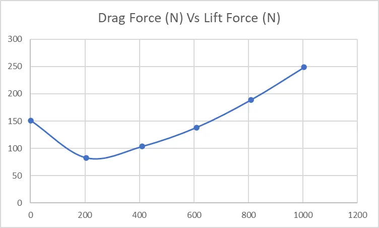
SG Force (X)1 denotes Surface Goal Force at X-axis which is called Drag Force.
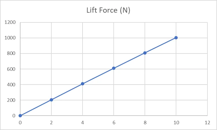
SG Force (Y)1 denotes Surface Goal Force at Y-axis which is called Lift Force.
Case: 1 Angle of Attack= 0deg
Velocity Contour
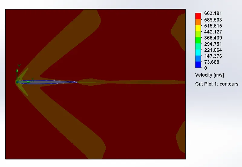

SG Force (X)1 represents Drag Force= 151.346 N
SG Force (Y)1 represents Lift Force= 0.305 N
Case: 2 Angle of Attack= 2deg
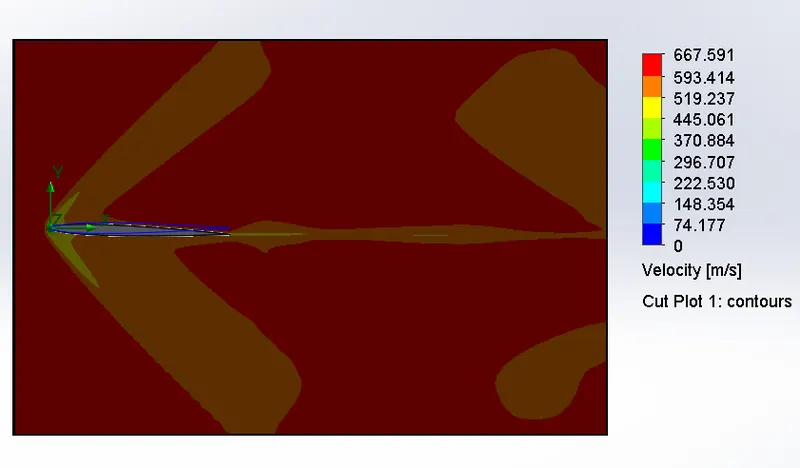

SG Force (X)1 represents Drag Force= 82.560 N
SG Force (Y)1 represents Lift Force= 205.342 N
Case: 3 Angle of Attack= 4deg
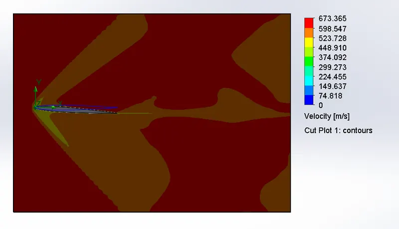

SG Force (X)1 represents Drag Force= 103.461 N
SG Force (Y)1 represents Lift Force= 410.239 N
Case: 4 Angle of Attack= 6deg
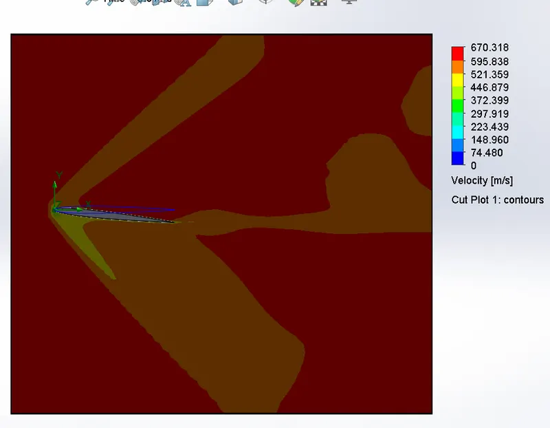

SG Force (X)1 represents Drag Force= 138.323 N
SG Force (Y)1 represents Lift Force= 609.878 N
Case: 5 Angle of Attack= 8deg
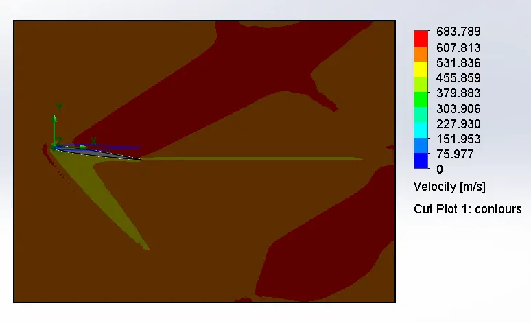

SG Force (X)1 represents Drag Force= 188.681 N
SG Force (Y)1 represents Lift Force= 808.886 N
Case: 6 Angle of Attack= 10deg
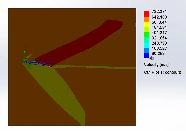

SG Force (X)1 represents Drag Force= 248.532 N
SG Force (Y)1 represents Lift Force= 1004.411 N
Comparsion Between Drag Force and Lift Force for Different Angle of Attack
| Angle of Attack (deg) | Drag Force (N) | Lift Force (N) |
| 0 | 151.346 | 0.305 |
| 2 | 82.560 | 205.342 |
| 4 | 103.461 | 410.239 |
| 6 | 138.323 | 609.878 |
| 8 | 188.681 | 808.886 |
| 10 | 248.532 | 1004.411 |
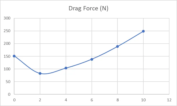
Angle of Attack Vs Drag Force
Angle of Attack Vs Lift Force
Drage Force (N) Vs Lift Force (N)
6. Conclusion
- Simulation for flow over NACA0017 airfoil at a different angle of attack was completed successfully using Solidworks Flow Simulation.
- As the angle of attack increases, the Drag force increases slowly, and the Lift force increases rapidly.
- As an increase in angle of attack, the velocity of air over the airfoil also increases.
Simulation models are in this Drive link:
https://drive.google.com/drive/folders/1qSY2dWY12tpQ6mxDOsiZpaMdcGmHmyYO?usp=sharing