HOW TO MODEL AND ASSEMBLE THE YACHT AND GIVE YOUR MODEL TO REALISTIC VIEW BY "AMAN GUPTA"
MODELLING AND RENDERING OF YACHT USING SOLIDWORKS
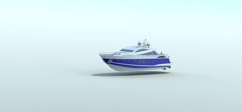
OBJECTIVE
The main objective of this project is used to create a model of different parts of the YACHT in solidworks
How to assemble these parts
To do a photo realistic rendering of a chopper in solidworks software itself
Introduction
Hi everyone…
Myself “Aman Gupta” Mechanical Engineer and here I have made YACHT using
the software “SOLIDWORKS” and now I will discuss methodology and tools used in the design process of this chopper.
PART MODELING
Part modelling you can create a part from a conceptual sketch through solid feature based modelling as well as build and modify parts through direct and initiative graphical manipulation.
FEATURE DESCRIPTION
1.Sketch
Sketch is 2D representation of the model with respect to the plane or view from outside of the model. These are also known as Entities ins solidworks . example are line, arc, spline, circles, rectangle etc.
2.Offset
You can use this tool by selecting the model edged or any sketch entities or any model faces by a specified distances.
3.Boss Extrude
This sketch used to convert a 2D sketch into the 3D Model.
4.Fillet
Used to create a rounded internal or external face on the part.
5.Lofted Base
The loft feature allow you to generate complex geometry in a single feature. It does this by interpolating surfaces between various cross-section of a model. These cross-section are considered “loft profile”
- Dome
It is used to create dome like shape without sketching 2D complex drawing.
7.Excrude cut
It is a another tool used to remove the material from the 3D model. It is just a opposite to extrude boss feature.
8.Split
This tool is used to project an entity onto other surfaces or curved/planer faces.
9.Trim entities
This tool is used to the trim any sketches or extend any sketches.
10.Revolve
This feature is used to revolve the 2d sketches around it. An axis should be there for revolving the 2d sketch.
11.Mirror
This tool is used t create the copy of the part to its another side. Mirror feature requires the plane and axis.
12.Combine
It is type of feature available in solid works to manually combine the two bodies
13.Shell
Used to define the thickness and of thin and thick shell elements
14.Champfer
A Cut on the edge or corner of something that makes it slope slightly rather than being perfectly square.
15.Circular pattern
This feature are used create are different number of instances required to create the pattern circularly.
16.Linearly pattern
This feature are used create are different number of instances required to create the pattern
Linearly.
SURFACE MODELLING
Surface modelling gives you the ability to build out of visual representation of an objects exterior and its contours.
Features description
1.Lofted surface
2.Swept surfaces
3.Filled surfaces
4.surface trim
5.Extend surface: it I s used to knit the two free edged/open edges of the surfaces together.
Also it reduces the gap between two edges of the surfaces.
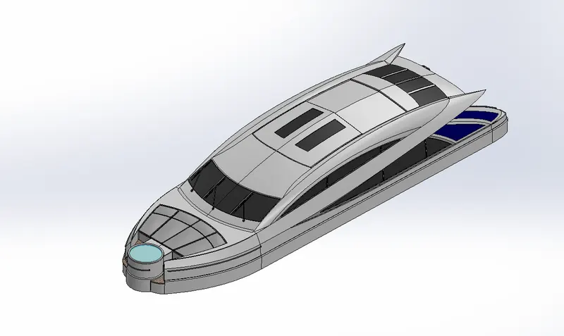
Superstructure
A superstructure is an extended construction of any building or platform that rises above the rest of the building or platform in a distinct manner.
Superstructure means to add a construction to an already existing structure. In ships this is the name given to the part of the ship that emerges from the deck.
The superstructure is mostly designed in fashion as well. This is because it is the most easily visible part of the ship, in fact it is the identification of the ship, and so the designers try to provide it with the identity that is unique.
HULL
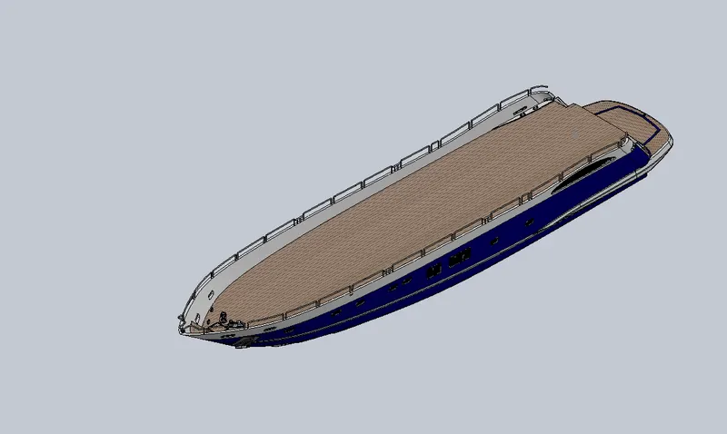
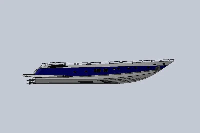
To define the hull, it can be said that it is the watertight enclosure of the ship, which protects the cargo, machinery, and accommodation spaces of the ship from the weather, flooding, and structural damage. But this alone does not suffice our requirements of understanding all the aspects of a ship’s hull.
The above figure shows the schematic profile of a conventional ship’s hull.
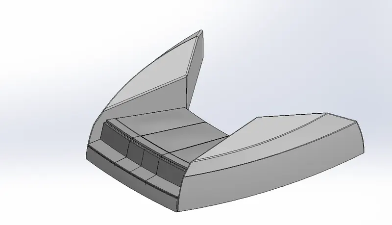
FRONT SEAT
Front seat was placed in front of the superstructure on the hull. It was designed after importing the deck surfaces of the hull as interface surfaces .
Command used_ sketch, offset entities, swept surfaces , extrude surfaces trim surfaces filled surfaces lofted surfaces knit surfaces chamfer revolved boss extrude cut mirror dome fillet.
MIDDLE SEAT
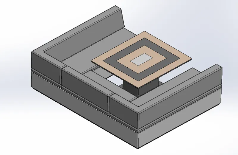
Middle seat was placed in the shaded area closely behind the superstructure backdoor. Unlike the front and rear seat the middle seat was designed using solid modelling commands.
It was designed after importing the deck surfaces of the hull as interface surface.
Commands used – sketch, offset entities, extrude boss, chamfer, fillet, mirror, extrude cut.
REAR SEAT
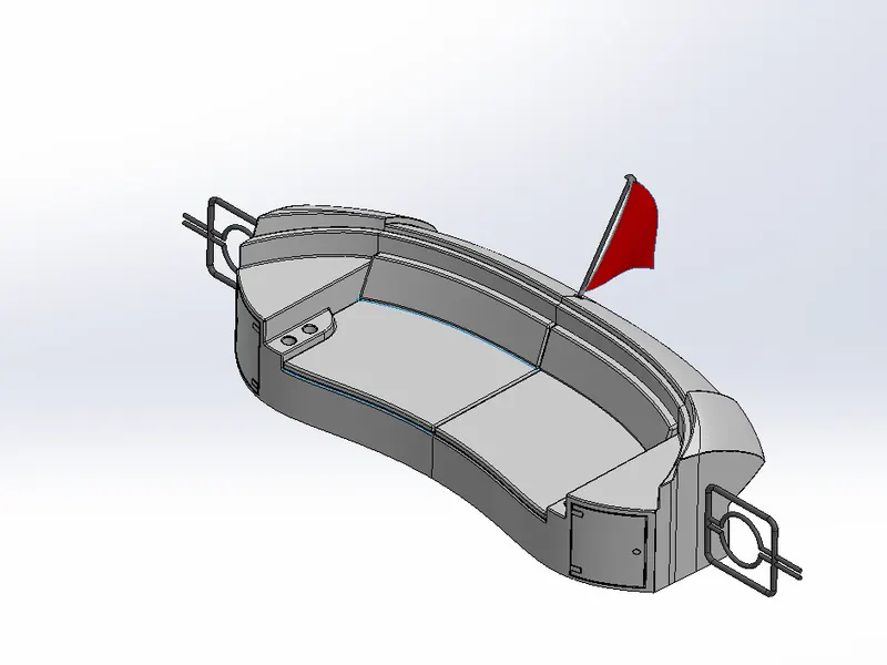
Rear seat was placed over the garage behind the superstructure. It was designed after importing the deck surfaces of the hull as interfaces surfaces.
Commands used- sketch, offset entities, swept surface, offset surface, trim surfaces, ruled surfaces, knit surfaces, extended surfaces, extrude surfaces, loft surfaces, extrude boss, extrude cut, chamfer, fillet, swept boss, mirror, revolved boss.
RADAR
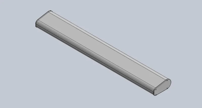
Radio Detection and Ranging, is used to detect objects and their position relative to your current location. It works by sending out a radio signal. When the signal hits an object, it gets reflected back to the radar, which can then calculate a rough estimate of the object. It does so by detecting other ships and land obstacles, to give bearing and distance for collision avoidance and navigation while on water.
A marine radar device acts as a major navigation aid for boaters. It helps in detecting boats, birds, landmasses, and weather systems - even if the visibility is less than usual.
Commands used-sketch, offset entities, convert entities, extrude boss, extrude cut, sketch driven pattern, mirror, split lines.
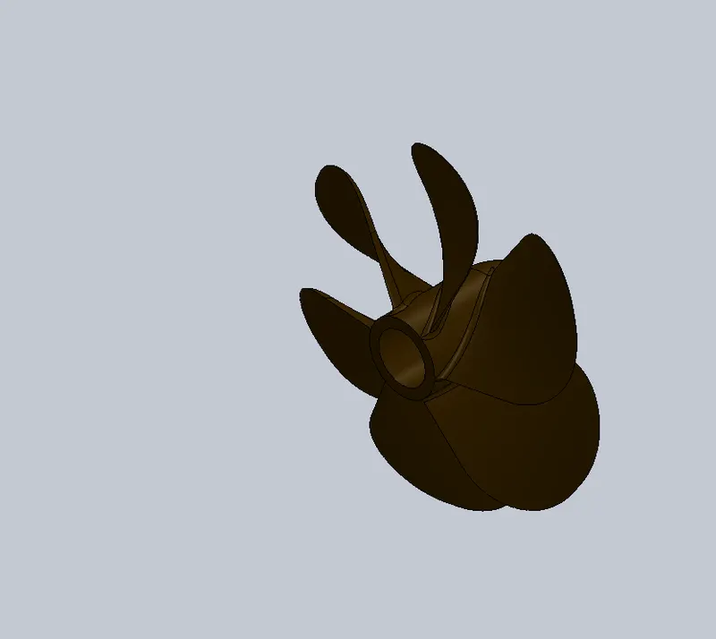
PROPELLOR
A propeller is a type of a fan that transmit power by converting eotational motion into thrust. A pressure difference is produced between in froward and rear surfaces of the air foil shaped blades and a fluid(water in this case) is acceleratedby the pressure differences.
Commands used – sketch revolved boss lofted boss fillet extrude cut circular pattern.
Radar mast
The radar mast supports the radar antennas satellite domes and lights. It was designed after importing the top surfaces of the superstructure as interface surfaces.
Commands used- sketch, offset entitie, extrude boss, fillets revolved boss swept boss mirror project curve chamfer dome shell.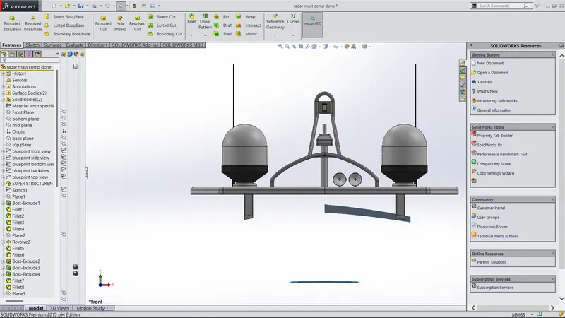
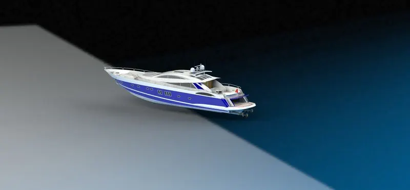
Assembly of yacht
All the designed components are taken into the assembly section in solidworks and using different mating feature such as concentric, coincident, parallel etc.
The entire assembly of the yacht is created.
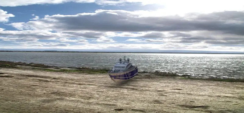
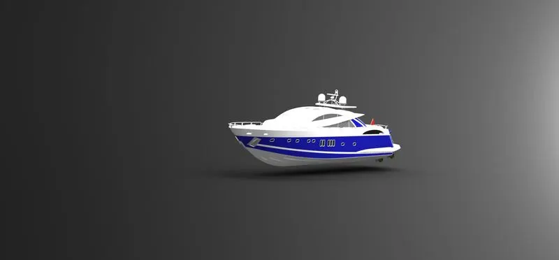
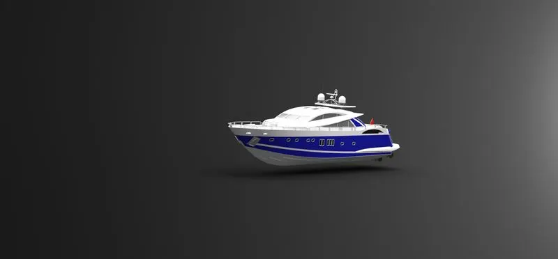
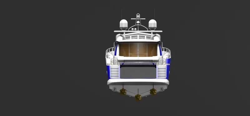
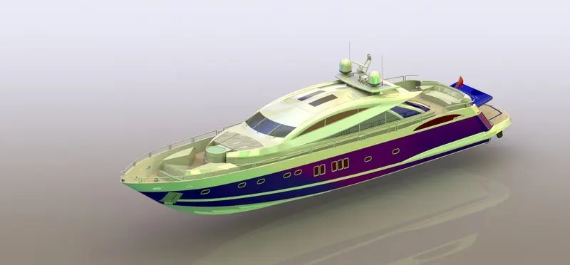
RENDERING IMAGES
It is the process of creating realistic image of the photorealistic model with the environment.
Thankyou......