AN AMERICAN CHOPPER MODEL BY AMAN GUPTA
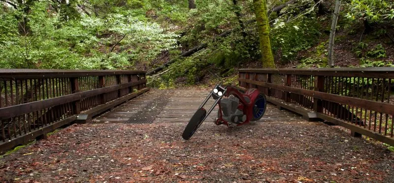
MODELING AND RENDERING OF AMERICAN CHOPPER USING SOLIDWORKS
OBJECTIVE
The main objective of this project is used to create a model of different parts of the American chopper in solidworks
How to assemble these parts
To do a photo realistic rendering of a chopper in solidworks software itself
Introduction
Hi everyone…
Myself “Aman Gupta” Mechanical Engineer and here I have made a American chopper bike using
the software “SOLIDWORKS” and now I will discuss methodology and tools used in the design process of this chopper.
PART MODELING
Part modelling you can create a part from a conceptual sketch through solid feature based modelling as well as build and modify parts through direct and initiative graphical manipulation.
FEATURE DESCRIPTION
1.Sketch
Sketch is 2D representation of the model with respect to the plane or view from outside of the model. These are also known as Entities ins solidworks . example are line, arc, spline, circles, rectangle etc.
2.Offset
You can use this tool by selecting the model edged or any sketch entities or any model faces by a specified distances.
3.Boss Extrude
This sketch used to convert a 2D sketch into the 3D Model.
4.Fillet
Used to create a rounded internal or external face on the part.
5.Lofted Base
The loft feature allow you to generate complex geometry in a single feature. It does this by interpolating surfaces between various cross-section of a model. These cross-section are considered “loft profile”
- Dome
It is used to create dome like shape without sketching 2D complex drawing.
7.Excrude cut
It is a another tool used to remove the material from the 3D model. It is just a opposite to extrude boss feature.
8.Split
This tool is used to project an entity onto other surfaces or curved/planer faces.
9.Trim entities
This tool is used to the trim any sketches or extend any sketches.
10.Revolve
This feature is used to revolve the 2d sketches around it. An axis should be there for revolving the 2d sketch.
11.Mirror
This tool is used t create the copy of the part to its another side. Mirror feature requires the plane and axis.
12.Combine
It is type of feature available I solidworks to manually combine the two bodies
13.Shell
Used to define the thickness and of thin and thick shell elements
14.Champfer
A Cut on the edge or corner of something that makes it slope slightly rather than being perfectly square.
15.Circular pattern
This feature are used create are different number of instances required to create the pattern circularly.
16.Linearly pattern
This feature are used create are different number of instances required to create the pattern
Linearly.
SURFACE MODELLING
Surface modelling gives you the ability to build out of visual representation of an objects exterior and its contours.
Features
1.Lofted surface
2.Swept surfaces
3.Filled surfaces
4.surface trim
5.Extend surface: it I s used to knit the two free edged/open edges of the surfaces together.
Also it reduces the gap between two edges of the surfaces.
PARS MODELED FOR AMERICAN CHOPPER
1.Transmission belt
2.Kickstand
- front fender
- rear fender
- chain
- oil tank
- pedal
- front wheel
- rear wheel
- chassis
- engine
- gas tank
- front fork
DETAILS OF PARTS USED IN ASSSEMBLY OF AMERICAN CHOPPER
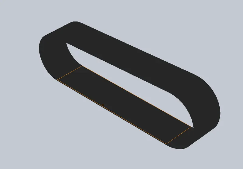
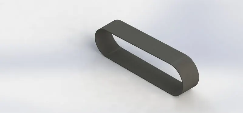
- Transmission belt: it is used to transfer the power from one pulley to another pulley.
Feature used: Boss extrude
Fillet.
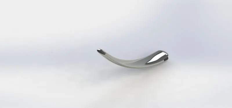
- Kickstand
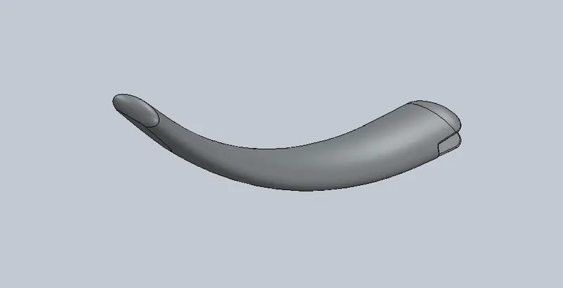
Feature used : loft
Dome
Extrude cut
Split
Boss extrude
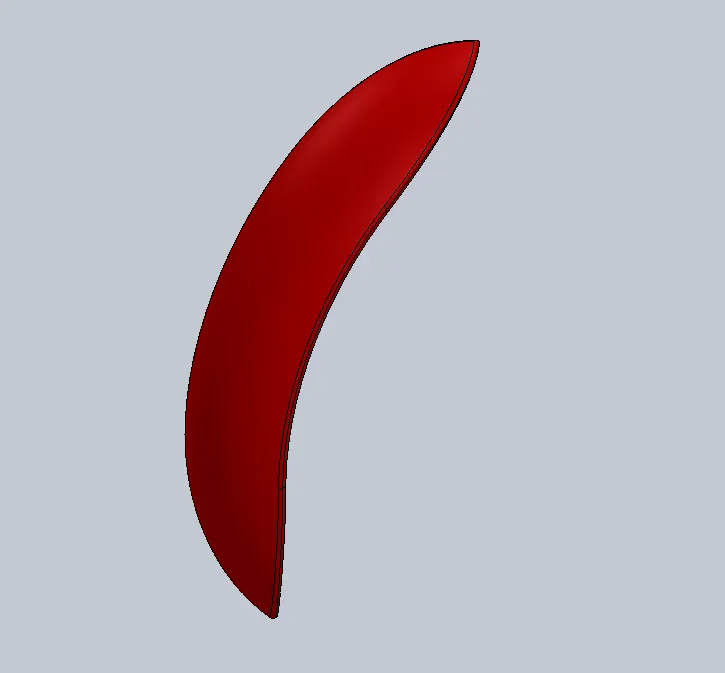
- Front fender
Feature used: 3 point arc
Revolve
Split
Fillet

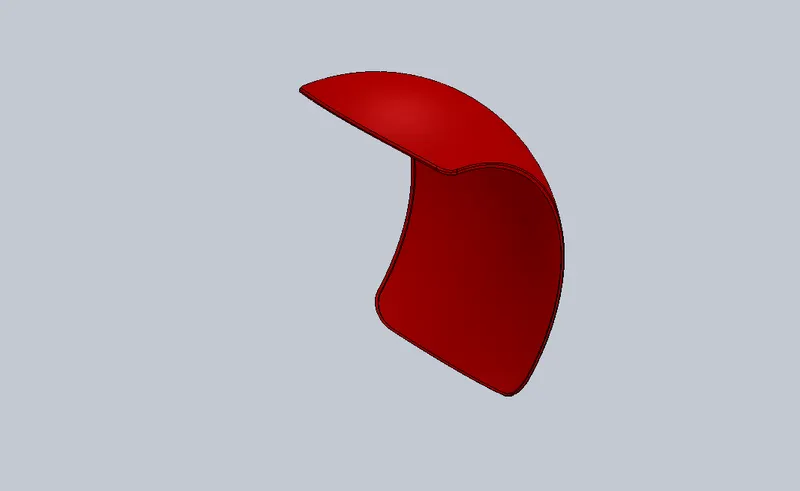
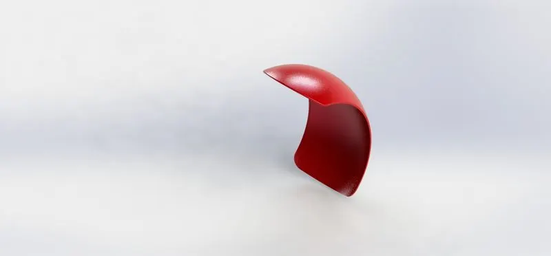
- Rear fender
Feature used: 3 point arc
Revolve
Split
Fillet
Shell
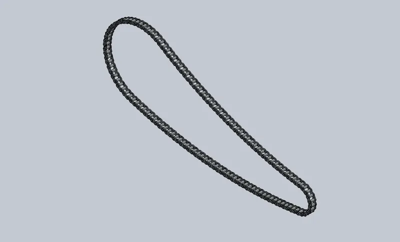
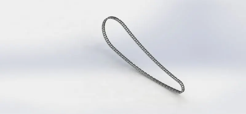
- Chain
Feature used: 3point arc
Slot
Boss extrude
Blocks
Curve driven pattern
Mirror , fillet
- Oil tank: oil tank is created by using the sketch and extruding it and also fillet feature have been used to give this a rounded edge.
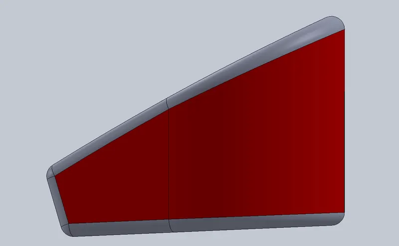
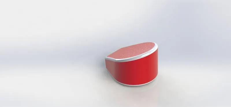
- Pedal: in creating a pedal for the bike basic sketch layout is drawn and then extruded it and then lever is created by using the revolve feature. On the ends of lever Dome is applied which gives a nice look to the lever. Chamfer is applied to created a pointed shape on the front part of the pedal. And finally the linear pattern is created and the fillets are applied.
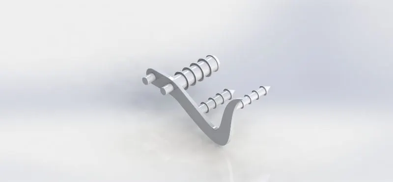
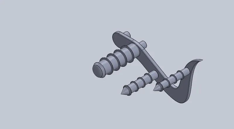
- Chassis: It is the most important part of the chopper bike, as the whole load and the parts are mounted on chassis. Modelled the chassis using the blueprint of the chopper and then two curves are drawn on two different planes and then projected the two sketches using the project curve command.
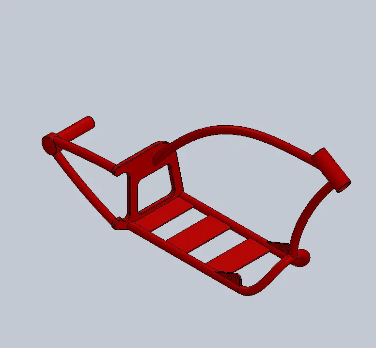
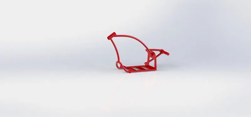
The projected curve is converted to sketch entities and the profile is created fro the sweep feature to be applied. Split command is used to consume the extra portion of sweep and then combine command used to join the two separated bodies. After the half session is modelled then the mirror command is used.
Feature used:
Sketch picture
Project curve
Sweep
Mirror
Fillet
Chamfer
Dome
Split
Linear pattern
Combine
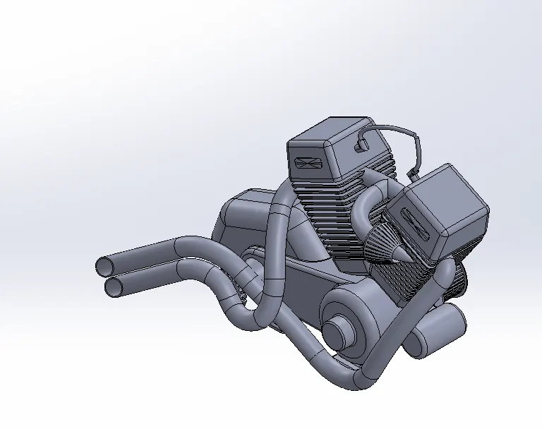
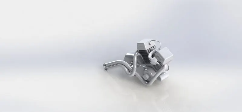
- Engine: The blueprint of chopper is used to create the engine.
Feature used:
Boss extrude
Fillet
Revolve
Reference plane
Circular pattern
Dome
Extrude cut
Mirror
Linear pattern
Split
Sweep
Composite curve
- Gas tank
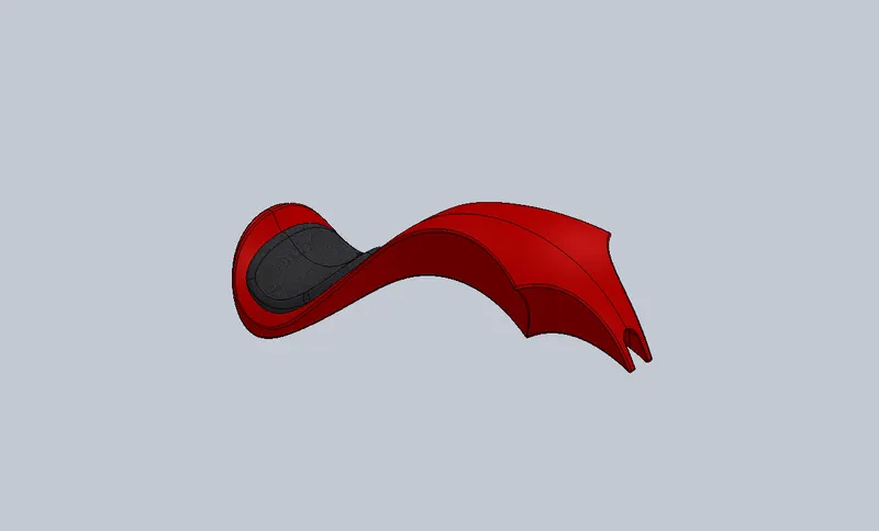
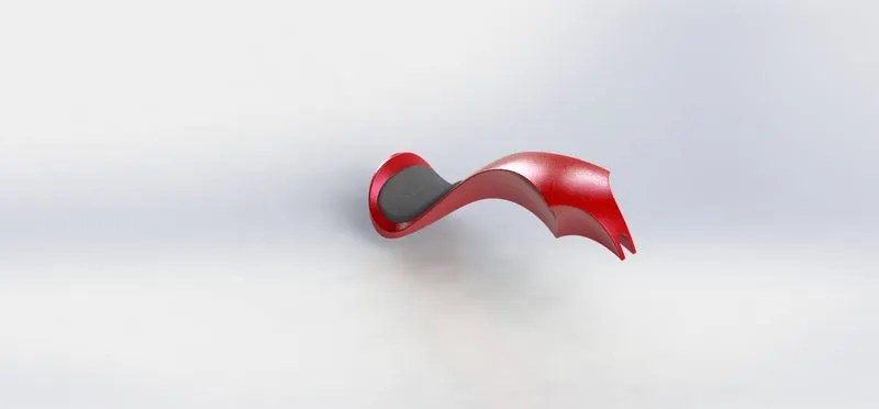
Feature used:
Surface loft
Boundary surface
Mirror
Split line
Reference plane
Surface extrude
Knit
Fillet
Swept cut
shell
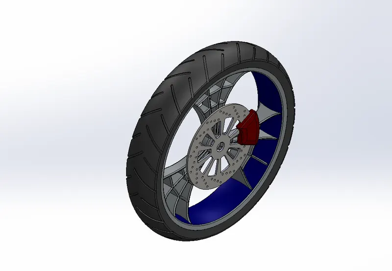
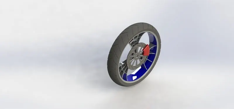
- Front wheel: fig
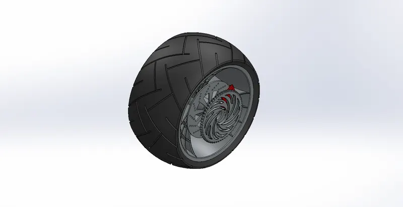
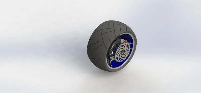
- Rear wheel: fig
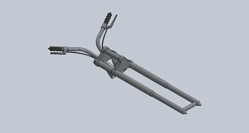
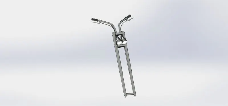
- Front fork: fig
ASSEMBLY
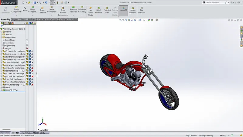
Assembly is the final bike where the different parts which we created are assembled using the different types of mates.
Firstly, in our case the parts are inserted using the bottom-up assembly approach. In context feature and top down assembly approach are also used for editing purpose.
RENDERING
Rendering is the photo realistic appearance given to any product which here In this case is the American chopper.
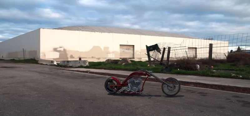
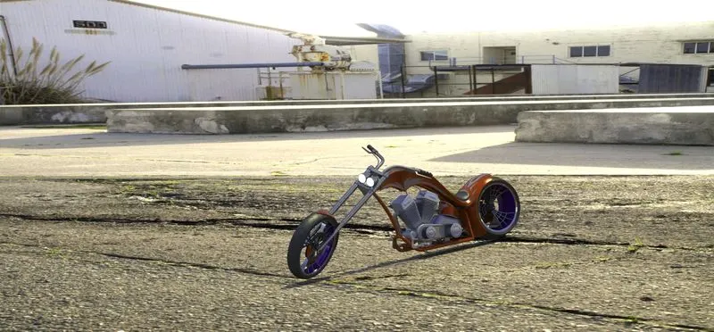
RENDERING ALPHA OUTPUT VIEW
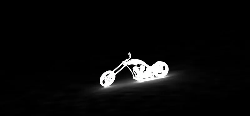
HERE I AM USING ONLY SOLIDWORKS RENDERING BCOZ I HAVE NOT ANY SOFTWARE OF SOLIDWORKS STANDARD VISUALIZATION.
THANKYOU.......