Radar Mast & Final Assembly of Yacht
Radar mast
REPORT
Yacht Model
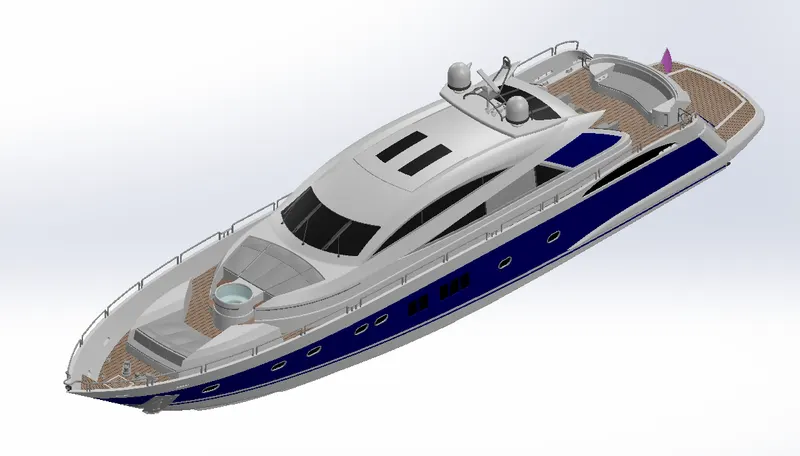
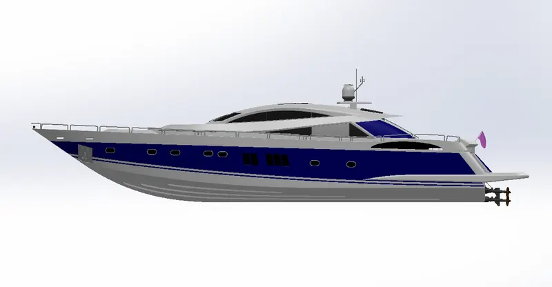
Objective- To model all the components of a Sunseeker Superyacht and render them after assembly in SolidWorks 2020.
Introduction-
A yacht is a motor boat or vessel used for pleasure, cruising or racing. It is a boat which has amenities to accomodate overnight use. To be termed a yacht, as opposed to a boat, such a pleasure vessel is likely to be at least 33 feet (10 m) in length and may have been judged to have good aesthetic qualities.
The Commercial Yacht Code classifies yachts 79 ft (24 m) and over as large. Such yachts typically require a hired crew and have higher construction standards. Further classifications for large yachts are: commercial—carrying no more than 12 passengers, private—solely for the pleasure of the owner and guests, or by flag, the country under which it is registered.
A superyacht(sometimes megayacht) generally refers to any yacht (sail or power) longer than 131 ft (40 m).
Racing yachts are designed to emphasize performance over comfort. Charter yachts are run as a business for profit.
This report is prepared to show the component wise design of the Superyacht using SolidWorks 2020.
Design Methodology-
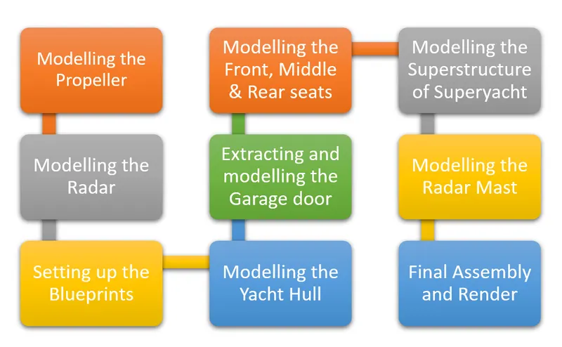
Description-
The basic tools for every component of the yacht are Line, Spline, Circle, Offset entities, Convert entities, Rectangle, Trim entities, and occasionally used were Slot and Split lines.
Sketch and Smart Dimensions is required to be used in every part created.
Since the yacht is symmetrical most of its components are also of the same kind hence, Mirror feature is used in most of the parts.
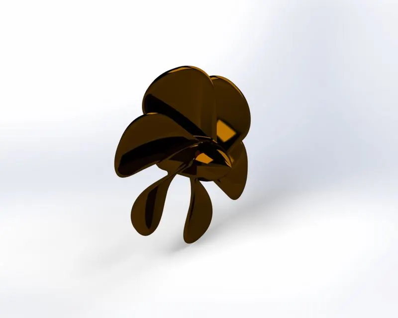
1. Modelling the Propeller-
A propeller is a device with a rotating hub and radiating blades that are set at a pitch to form a helical spiral, that, when rotated, exerts linear thrust upon a working fluid, such as water or air.
The propeller was designed starting from the boss and then creating the rotating blades on the periphery.
The features used are Revolve, Solid Loft, Fillet, Extruded Cut, Circular pattern, etc.
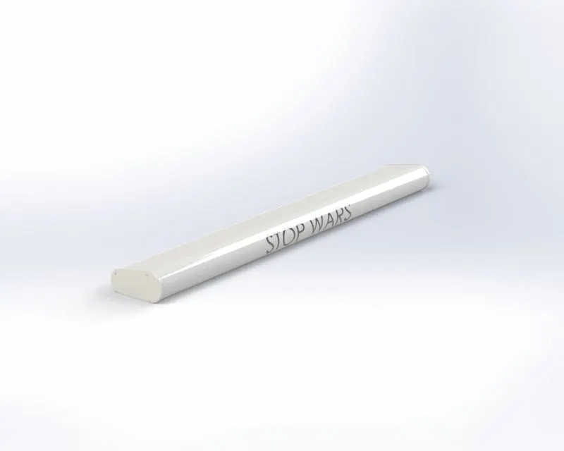
2. Modelling the Radar-
Radar(radio detection and ranging) is a detection system that uses radio waves to determine the distance (ranging), angle, and radial velocity of objects relative to the site.
The radar is designed by sketching the cross section and then boss extruding it, later finished by applying details.
The features used are Boss extrude, Cut extrude, Fillet, Sketch Driven Pattern, Mirror, Text addition and Split Line.
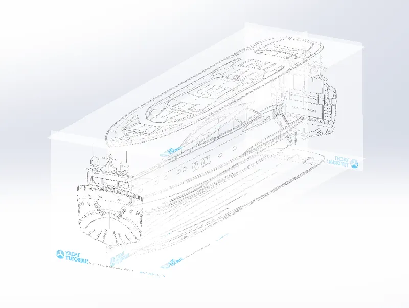
3. Setting up the Blueprints-
The blueprints are sketch pictures of an object, in this case a yacht of every possible view. This facilitates the creation of sketches to ease the process of design. Pictures from the Front, Back, Side, Top, Bottom are used to sketch accordingly and to connect the various sketches of different views accurately.
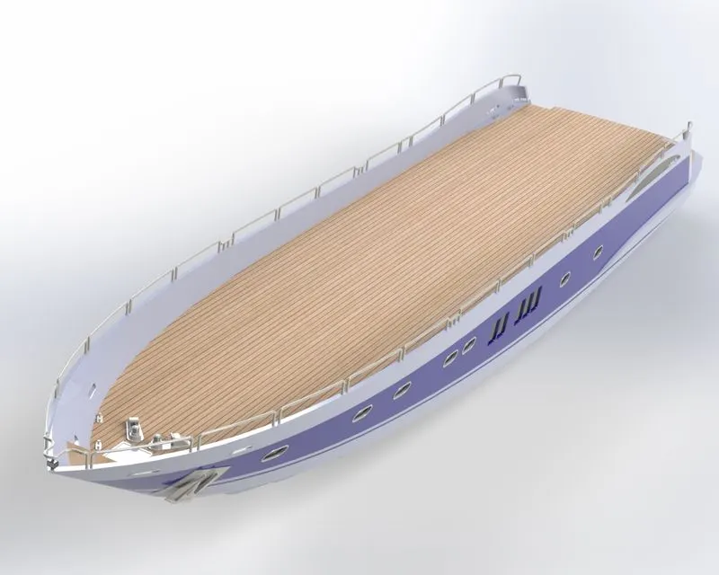
4. Modelling of the Hull-
A hull is the watertight body of a ship, boat, or flying boat. The hull may open at the top (such as a dinghy), or it may be fully or partially covered with a deck. Atop the deck may be a deckhouse and other superstructures, such as a funnel, derrick, or mast.
The base of the hull is first design with the help of projected curves and surface loft. Then the other details such as the floor, railing, windows, stairs, etc are added.
Features used are Projected curve; Surface- Trim, Loft, Extrude, Knit, Fill; Cut and Boss extrude; Fillet and Chamfer, Linear pattern, Solid Sweep, Revolve, Dome, Helix/Spiral and Decals are applied to the floors.
While designing the parking area, a block of solid is extracted to create the space which is then saved to design the garage door in the next part design.
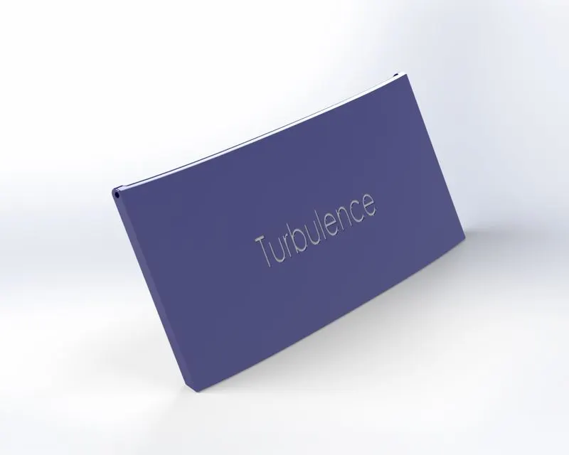
5. Modelling the extracted Garage door-
The garage door is a door to the vehicle parking space provided in the hull part of the yacht.
The block acquired from the hull is cut extruded to have the garage door thickness and then is applied with details.
Features used are Cut extrude, Shell feature, Fillet and Text.
6. Modelling the Front, Middle and Rear seats-
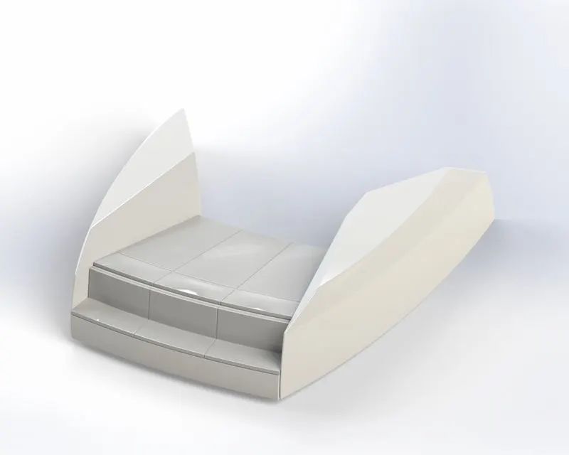
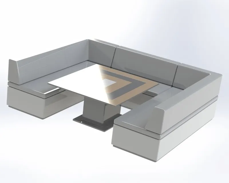
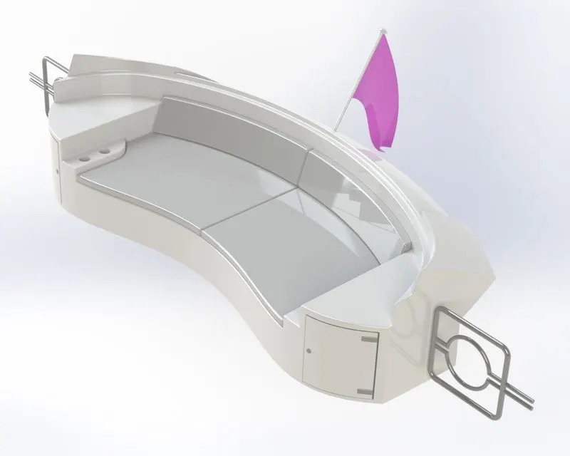
The seats are merely used for passenger sitting. Seats are provided on three locations of the yacht. These are cushioned and made soft for the passenger to enjoy without any discomfort.
The seats are simply made by sketching and extruding. Dome feature is used to give the cushions a puffy look.
Features used are Surface- extrude, sweep, knit, trim, loft, fill, ruled, extend; Fillet and Chamfer, Cut extrude, Revolve.
i. Front seat
ii. Middle seat
iii. Rear seat
7. Modelling the Superstructure-
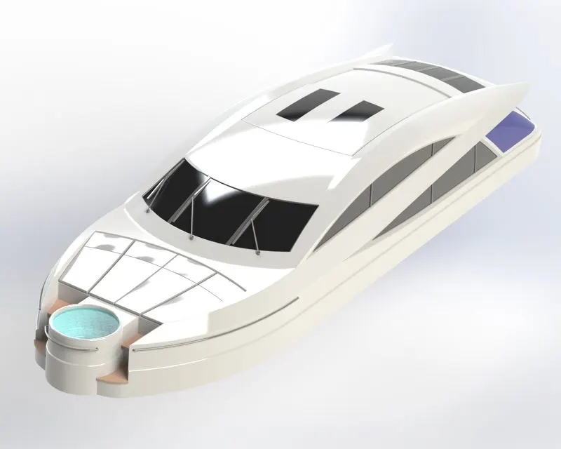
A superstructure is an upward extension of an existing structure above a baseline. On a water craft, the superstructure consists of the parts of the ship or a boat that project above her main deck.
Projected curves are used to create the curved contours of this part and then filled with surface fill and loft. After achieving the solid part details such as windows, doors, stairs, jacuzzi, wipers, etc are added.
Features used are Surface- extrude, sweep, knit, ruled, trim, loft, fill, extend, thicken; Fillet and Chamfer; Projected Curves; Boss and Cut extrude; Solid sweep; Dome. Decals are applied to the stairs in the front of the superstructure.
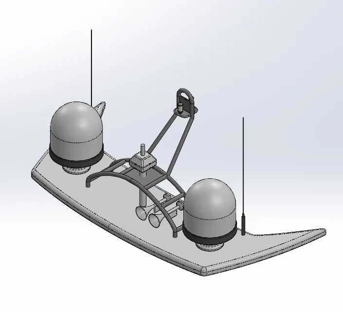
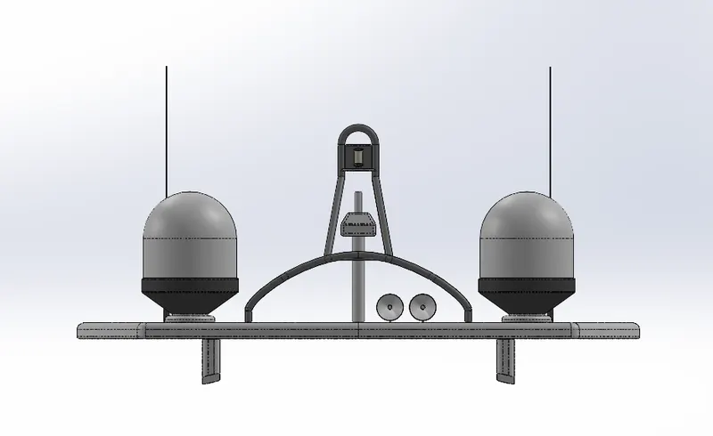
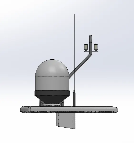
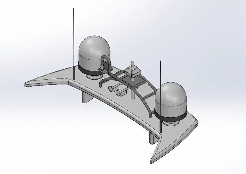
8. Modelling the Radar mast-
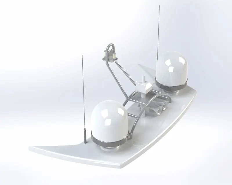
The mast of a sailing vessel is a tall spar, or arrangement of spars, erected more or less vertically on the centre-line of a ship or boat. Its purposes include carrying sails, spars, and derricks, and giving necessary height to a navigation light, look-out position, signal yard, control position, radio aerial or signal lamp.
The base is modelled first and then the other auxilliaries on top of it.
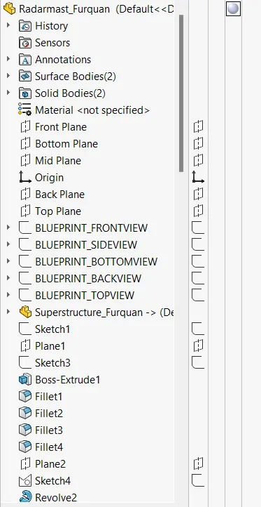
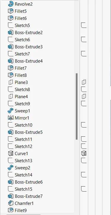
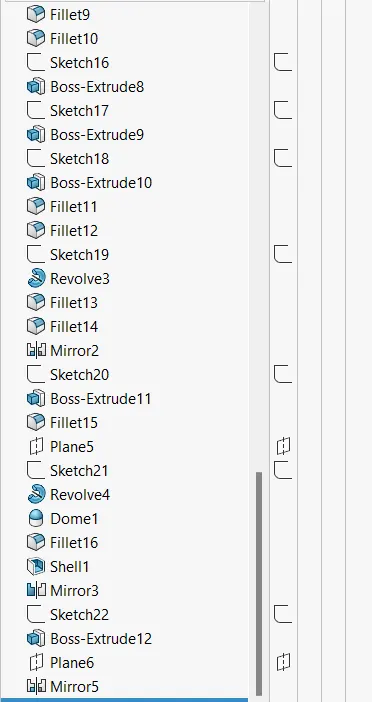
Features used are Boss extrude, Fillet and Chamfer, Revolve, Solid sweep, Projected curve, Dome and shell feature.
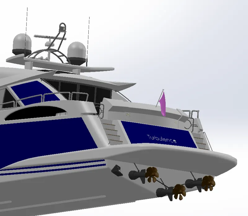
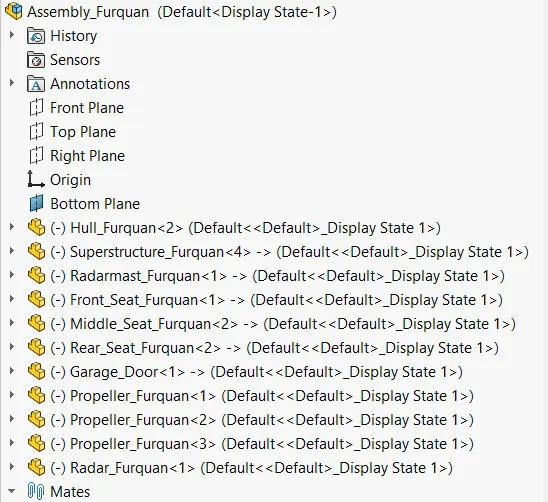
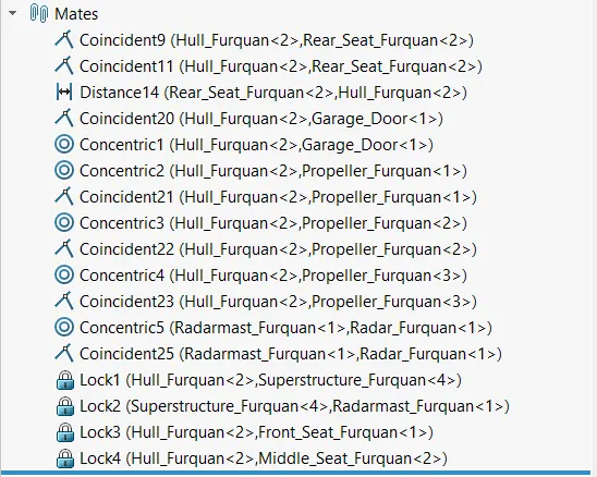
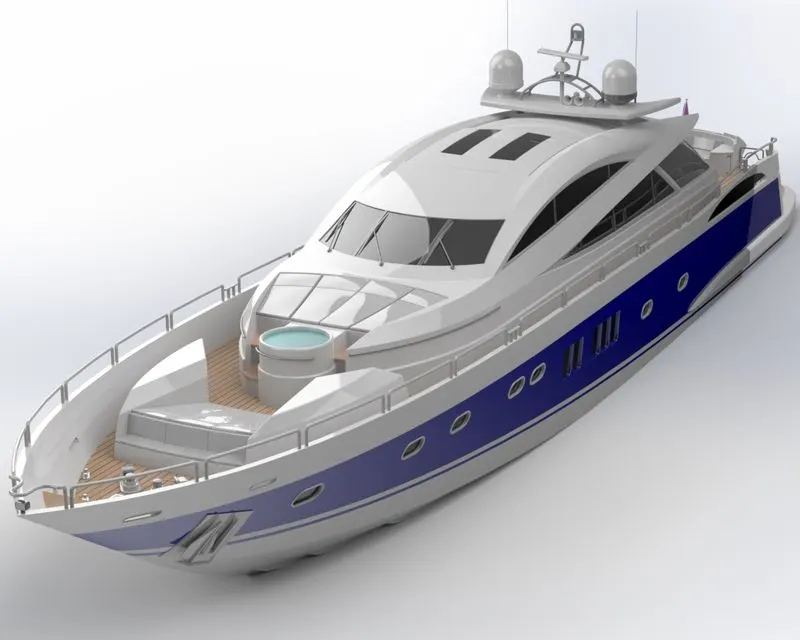
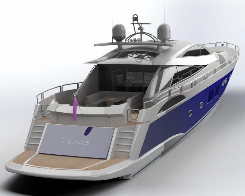
9. Assembly of Sunseeker Superyacht-
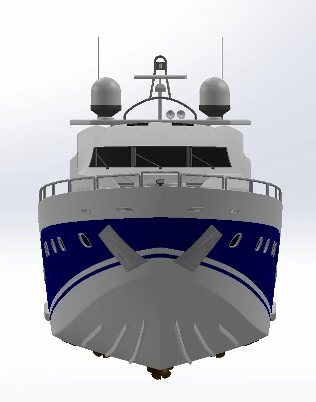
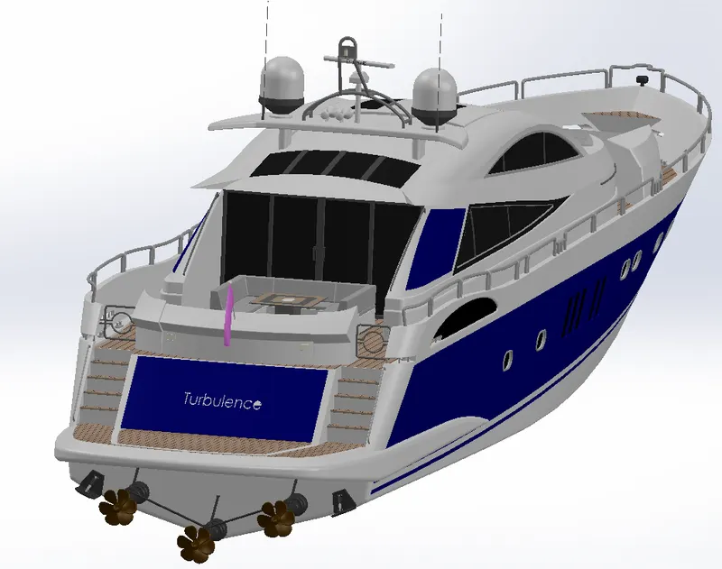
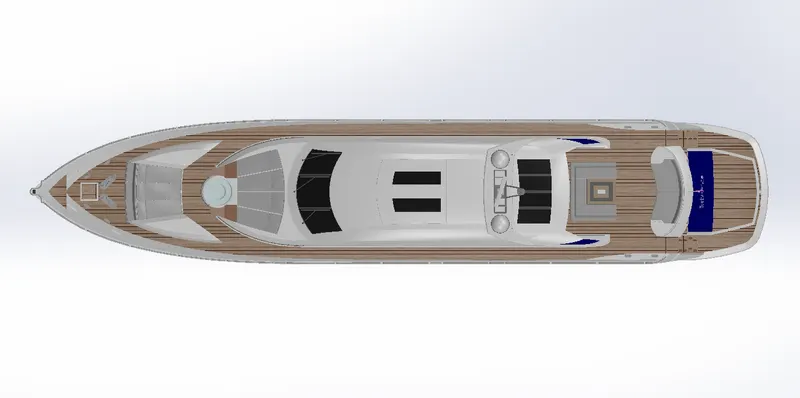
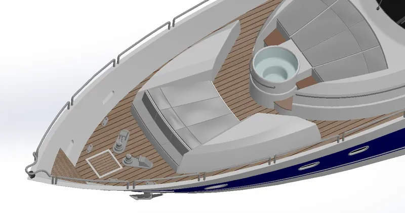

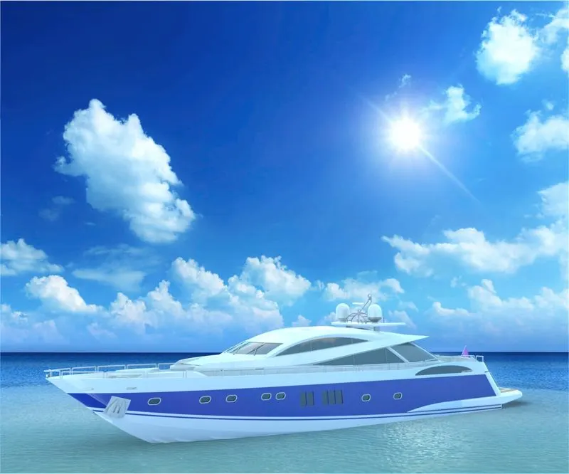
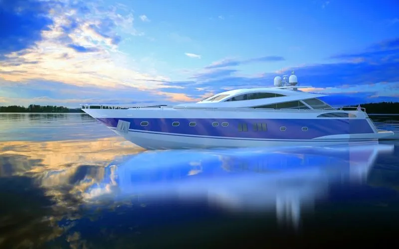
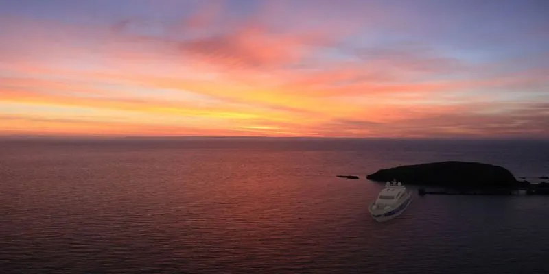
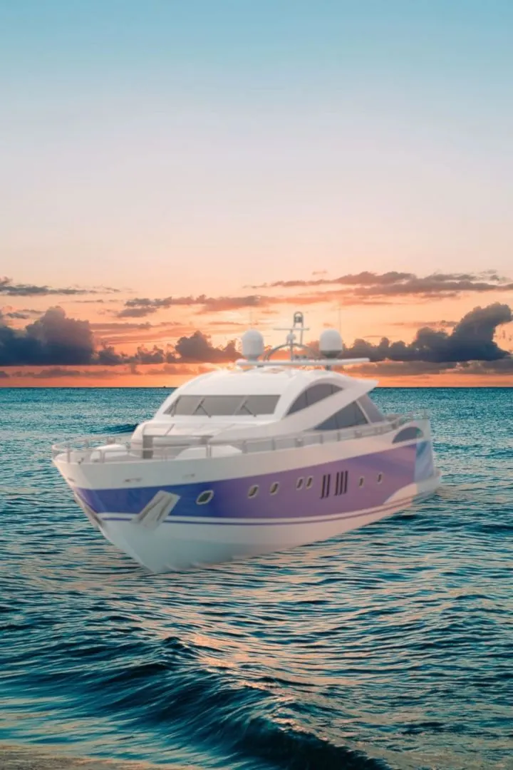
Renders-
Conclusion-
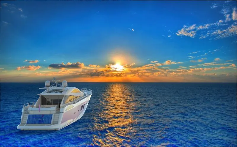
This modelling of the Sunseeker Superyacht made me familiar to various tools in solidworks especially modelling and designing using projected curves. The method to design components at particular co-ordinates which properly places them within the assembly and cuts down the efforts of mating while assembling the components. I learnt how to properly apply decals using the label options. The text engraving/debossing on parts using the text feature and cut extrude was familiarized. Rendering using SolidWorks Visualize got more efficient for me. Adding new backplates, environments and tweaking the settings are some of the activities that was performed while rendering. All in all this project has covered almost every aspect of design methods and made aware all the features and tools of SolidWorks.