Radar Mast & Final Assembly of Yacht
DESIGN AND ASSEMBLY OF YACHT IN SOLIDWORKS 2018
(https://drive.google.com/drive/folders/1BHD9W5TjnbIabgZtRinQVQFlaUT2wUZI?usp=sharing)
OBJECTIVE
Design and Assembly of a yacht in Solidworks 2018 by using various tools and features and image rendering the model using solidworks visualization.
INTRODUCTION
Solidworks is an CAD (computer aided design) software used to design any kind of objects in 3D which is extruded from fully defined 2D sketches and geometries. The software was developed by DASSAULT SYSTEMS located in Velizy-Vilacoublay, France. The aim of the software is to creates perfect and detailed solid body, though it has various tools such as surface modelling, sheet metal modelling, photo view 360 and more. It is finest and User-friendly software which allows us to get through the features and tools quickly. Here, we were going to overview and research various tools and features used in designing the yacht.
DESIGN METHODOLOGY
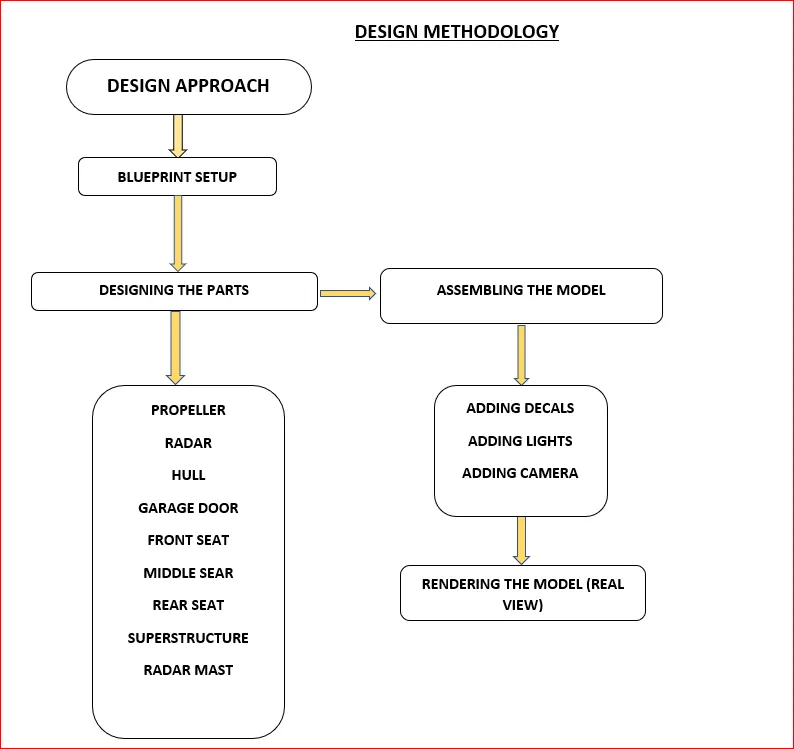
(Saving the parts individually every time after done with modelling to re access and rebuild the model in future)
(NOTE: Start the solidworks application and select PART option to design the model needed. After selecting the part, it directs to the window where the FEATURE TREE is seen in the left corner of the window and PLANE is situated in feature tree. Rename the plane according to the convenience to the sketch to be drawn. Finally select the concern plane and start to sketch. This is initial step for every model to be designed in solidworks.)
1.BLUEPRINT SETUP
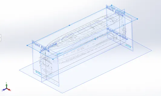
Start the solidworks application and go to part option to set up the blueprints reference to sketch the model. Blueprints provides the ideation of the sketch with perfect geometrical dimension. After setting the blueprints in plane, the sketching of parts can be start with concerned plane with reference to the blueprints.
2.PROPELLER
Propeller is a fan like structure mounted at the bottom of the yacht used to move them forward and backward steadily in the water. It is important part of the ship also associates with the direction it moves. The features used to design the propeller model includes
- Revolve
- Loft
- Fillet
- Circular pattern
REVOLVE is an attractive feature in solidworks which is used to create any kind of circular or spherical shaped object using a reference (sketch or plane). The feature is useful because of its wide options to modify the design in desired dimensions. Here the revolve feature is used to create the region to fit in the shaft of the yacht.
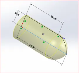
(Yellow region is revolve with blue line as reference)
LOFT- It is a handy tool used to join the two ends of the constrained sketches to complete the 3D look. It has a guide curve option which enables us to direct the loft in desired directions. In this case we used to loft two sketched portion which looks like fan to creates displacement in the water.
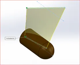
(Yellow shaded region is the loft created between two sketch)
FILLET- It is frequently used feature in designing a part in solidworks. It generally works on shaping the corners and sharp edges to give tangency look. It has a several option so that the feature could applied accordingly to the object with desired dimension. Here the fillets are applied to the fan to get the desired look.
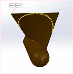
(Yellow markings are the regions to be filleted. Filleted image attached below)
CIRCULAR PATTERN- It is one of the handy tools in solidworks used to get multiple work done in one option also reduced the time to get done with the design of the part. Here the pattern is applied to generate the fan with number of instances required.
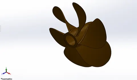
3.RADAR
Radar is commonly seen in most of the luxurious yacht. They were installed in yacht to stay connected digitally to other networks when weather is bad and guides ship and warns them. Radars usually receive signal from the satellite like other networks and uses radio wave signal to stay connected with other ship. The following feature is used to model the radar part
- Boss extrude
- Fillet
- Cut extrude
- mirror
- Sketch pattern
- Split line
BOSS EXTRUDE- This is commonly used feature in solidworks to convert the fully defined 2D sketched entities to 3D model. Here the feature is used to extrude the rectangle shaped structure in the right plane and mirrored in the future to get the complete radar model.
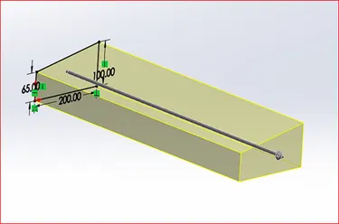
(Yellow shade are region extruded using sketch)
FILLET- It is applied at the corners and edges of the radar model to get the perfect finishing look and originality of the model.
CUT EXTRUDE- The cut extrude is one of the useful tools to remove/cut the portion in the model using the sketch in 3D model. Here the feature is used to cut the portion to set fasteners at the four corners of the radar.
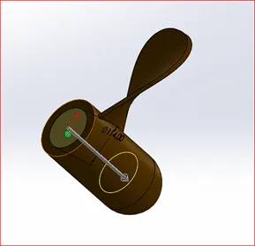
(Arrow mark indicates the depth level of region to cut)
MIRROR- The Mirror feature is most useful and handy one to create the parts in twin regarding to the plane. It allows to create the exact part from the parent that is already created. Almost it reduces the half of the time in designing the model which already exists and need one.
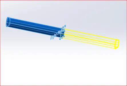
(yellow lines are region to be mirrored using parent blue region)
SKETCHED PATTERN- The sketched pattern used to pattern the sketch drawn in multiple needs. The corners of the radar needs to be sketched and patterned at the four corners to boss extrude the fasteners.
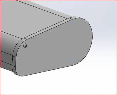
(Sketch pattern is marked in blue around the corners of radar highlighted in blue)
SPLIT LINE- The split line feature in this software is used to split the faces into multiple faces using the sketch basis for our designing convenience. Here the split line is created to add the sketch in radar.
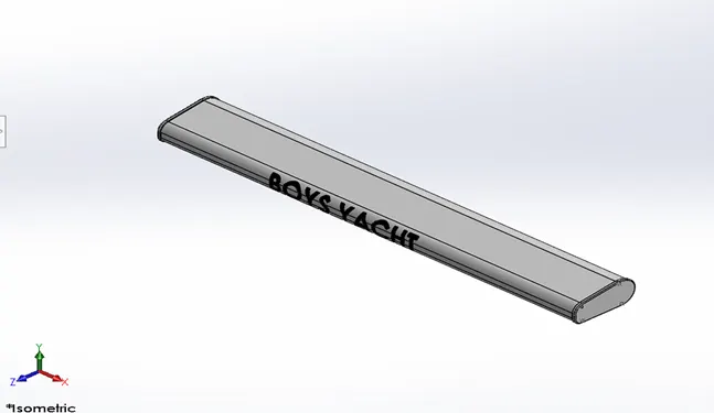
(split line is indicated in red arrow at the face where text is included)
4.HULL
Hull is the huge part of the yacht, and it forms the major portion of the ship. There are several components includes in the hull part. Lot of features are used to create a hull part includes
- Projected curve
- Surface loft
- Surface extrude
- Surface trim
- Surface knit
- Shell
- Boss extrude
- Cut extrude
- Fillet
- Sweep
- Chamfer
- Dome
- Helix/spiral
- Linear pattern
- Revolve
- Surface offset
- Mirror
CURVE PROJECTION- it is a noticeable feature provided by a solidworks. It is basically working on projecting two different sketches on a two different plane to form a 3D curve. Curve projection is used often in the hull part to design the outer surface body of the yacht using the curve.
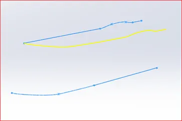
(Blue curves are sketched curves and yellow curve is projected curve based on two curves)
SURFACE LOFT- After the curve projection, they were joined, or surface is formed using surface loft feature with guide curves used in the direction of the curve the surface needs to be generated. This feature is used across the modelling of hull and complete yacht
SURFACE EXTRUDE- it is created in midplane to trim the rear portion of the yacht to give the closed surface of the hull part. It is usually done extruding open single sketch for generating the surface.
SURFACE TRIM- This is one of the essential features to trim the surface or removing it from the part design. Here the surface trim is used to remove the extra portion or the unnecessary region in the hull to get the desired shape of the model.
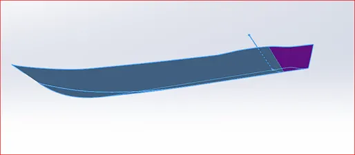
(Violet region will be removed with reference to line in blue)
SURFACE KNIT- It is a unique feature used to merge two or more faces or surfaces join to forms a single body and creates a solid body where it is necessary. Here the surface knit is done after forming multiple surface bodies to avoid any gaps and to form solid structure at the end of model.
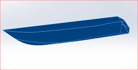
(all the surface combined using knit surface to fill minor gaps)
SHELL is an extremely useful feature that allows us to remove the inner regions of solid bodies and makes it hollow. It creates open shell and closed shell as well. Here the option is used to make the closed shell in the hull after completing one side of it.
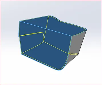
(solid bodies shelled and the thickness of shell is shown in yellow)
BOSS EXTRUDE- the feature is used to extrude various solid components in hull parts such as anchor holder and the pulleys and more.
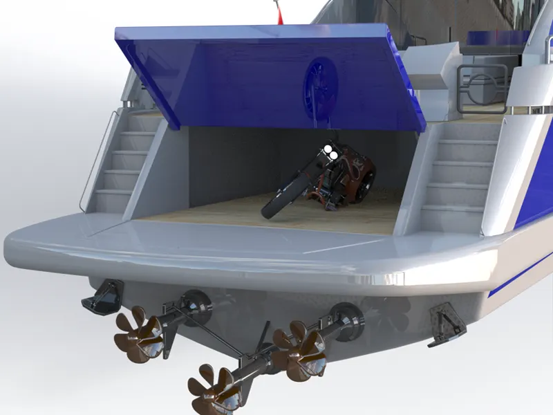
CUT EXTRUDE- it is used to remove/cut the portion in the propeller shafts and the suspension components and at other parts of the hull like windows and doors. At the back end of the hull part, small amount of space is removed using cut extrude for garage to park/carry vehicles at the yacht.
FILLET- fillets are done at various edges and corners of the hull to look better and realistic of the model after completion and in renderings.
SWEEP- one of the finest features of solidworks which is used to form a hollow and solid pipe in desired dimensions with the help of two sketches (circle and path). It is a time saving features that enables us to instantly design the model to be designed. Here the sweep feature is used to design the fence rods at all sides of the hull for people protection.
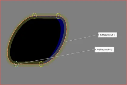
(Yellow shaded region is the sweep with reference to circle sketch shown in yellow)
CHAMFER is a feature works nearly to the work done by fillet, but it forms a flat portion by removing the extra portions in the edges or corners to get a desired shape. Here the chamfer is applied to form the calculated view of the back region of the hull part.
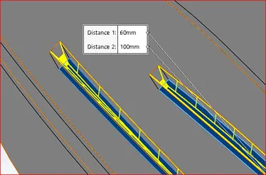
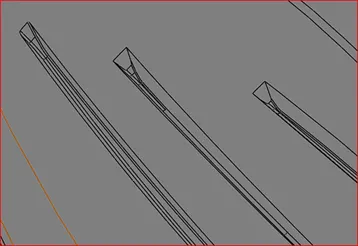
(Yellow lines are the regions to be chamfered and next image is after chamfered)
DOME- This feature is particularly useful to completes the flat ends of the objects by creating a semi sphere structure to give the perfect look of the design. Here the dome is applied at anchor holders.
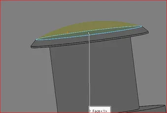
(Yellow shaded region is the dome region to be formed)
HELIX/SPIRAL- this is unique feature in the hull part as it created the helix or spiral shaped solid spring like structure, the sketch is drawn using the helix feature and made into solid body using the sweep feature.
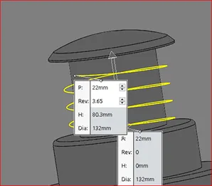
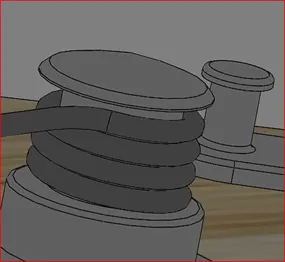
(Yellow spiral lines creates the spring in next image)
LINEAR PATTERN- the linear pattern in the hull part is to create n number of same components in linear direction with the help of reference line.
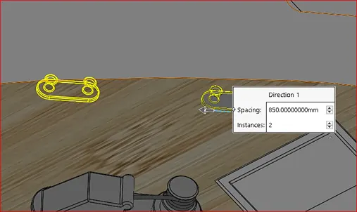
(Yellow lines are the part to be created using parent part behind it)
REVOLVE- here the revolve feature is used to create the cylindrical structure like spring holders at the front end of the yacht.
(SURFACE OFFSET is kind of special feature applied here to use it in future modelling purpose. The surface offset is done at the deck surface of the hull part and the offset is hided because it has no role in the actual part but in later parts to be modelled. All other parts must be assembled at the surface of the deck. So, offsetting the surface and designing other models with reference to the surface offset will allow the models to directly assemble in deck surface later.)
MIRROR- after complete modelling the one side of the hull part, the other portion will be mirrored using the mirror feature. This tool is very useful to create the twin parts with the help of parent part with reference to the plane or any flat face in which the mirroring takes place. Below images are the complete hull part after mirroring.
HULL PART
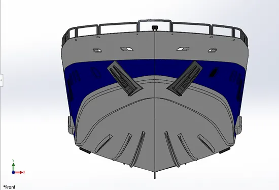
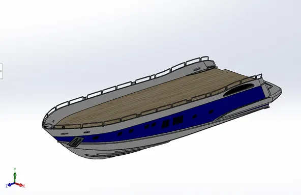
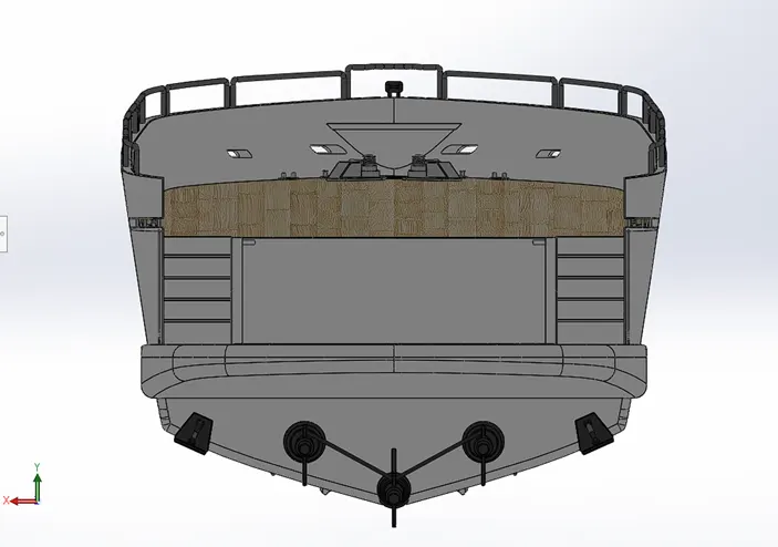
After complete modelling the hull part, appearance works needs to be done by adding decals on the deck surface, coloring for the fence rod, ship logo, window and at other parts of the hull.
GARAGE DOOR
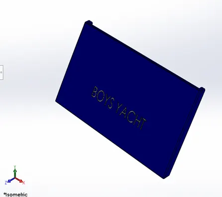
while modeling the hull part, particular space is allotted for garage whereas a portion is removed using cut extrude and later used to create a garage door which matches the dimensions of the garage door. One side of the garage door is extruded to fit in the garage and filleted. The remaining portion of the garage door is generated using mirror option. Later the appearance and text(option) is added to the garage door to look colorful and real.
FRONT SEAT
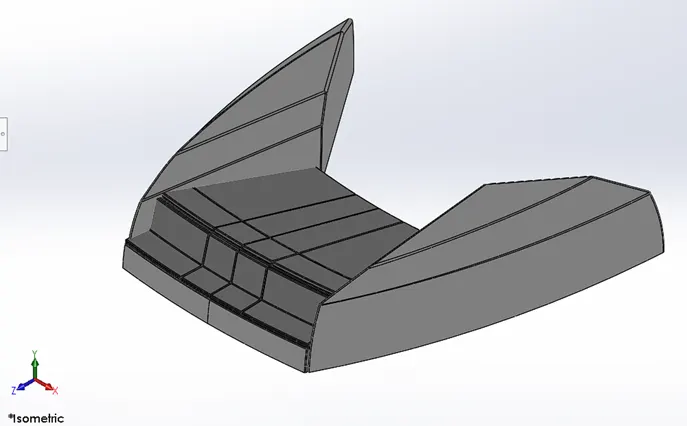
After completing the hull part and garage door, front, middle and the rear seats are designed. The seats will give the yacht more furnished, and luxury look where we can sit and relax at evenings and mornings. The seats are designed individually using surface offset as a reference created during the modelling of hull part. The features used to model the front seat are followed
- Surface sweep
- Surface extrude
- Surface fill
- Surface trim
- Surface loft
- Surface knit
- Chamfer
- Revolve
- Cut extrude
- Cut extrude-thin
- Fillet
- Mirror
- Dome
SURFACE SWEEP is done to create the side surface portion of the seat which follows the sweep and the path. The sketch is done on the deck surface which needs to be inserted in new part(blueprint) initially. The sketch follows the blueprints front top view as a reference with required dimensions. SURFACE EXTRUDE is done wherever necessary and to extrudes the sketch into surface model. SURFACE FILL is used to fill the surfaces with more than one open edges. It is useful tool to create the instant surface part with reference to the edges.
The unwanted parts or the surface parts are removed using SURFACE TRIM and the feature is often used in surface modelling. SURFACE LOFT is used to create the surface region with respect to the guide curves or with instance to the two edges of the surface. SURFACE KNITTING the region to combine the surface body and to fill the minor gaps to avoid any error in the future steps. CHAMFER feature is used to create the shape at the edges with two different distances or dimensions. REVOLVE is used to generate the front region of the seats with seating. CUT EXTRUDE is used to cut the surface part using the sketch drawn in top plane to differentiate the seating. FILLET is made at all corners and edges of the model to generate the realistic look and betterment in renderings. MIRROR is applied to create the part modeled at one side of the deck surface to produce the same portion over other side using plane or face as a reference. DOME is applied at the top of the surface body to give the better look.
MIDDLE SEAT
After completing the front seat, the middle seat is modelled using the following feature
- Boss extrude
- Chamfer
- Fillet
- Mirror
- Cut extrude
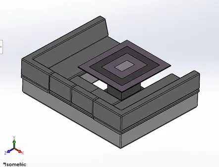
Comparatively the middle seat is a simple design which fits behind the garage of the yacht. Same as before the blueprint part is opened and surface offset part is inserted and to begin sketch using top view blueprint as reference. BOSS EXTRUDED the sketch drawn at the deck surface. The boss extruded body is CHAMFERED and FILLETED at required dimensions at the corners and edges of the seat. Using MIRROR feature the remaining twin part of the seat is created with reference to the mid plane or the flat face in where the region taken as a reference.
REAR SEAT
After modelling the front and middle seat, its time to place the rear seat for the yacht. The rear seat is placed at the dead end of the deck surface. As usual the model is sketched and created in deck surface using top view blueprint as reference. The feature used to design the rear seat are
- Surface sweep
- Surface offset
- Surface trim
- Ruled surface
- Surface knit
- Surface extend
- Surface loft
- Surface fill
- Boss extrude
- Cut extrude
- Chamfer
- Fillet
- Sweep
- Mirror
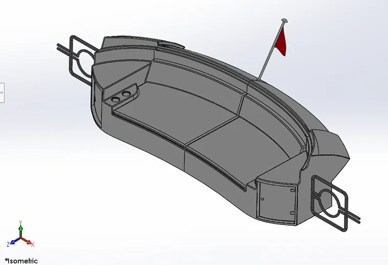
SURFACE SWEEP is applied initially with sketch and the follow path to generate the surface body of the seat. SURFACE OFFSET is created for required dimension and SURFACE TRIM is used to trim the excess surface body wherever necessary. RULED SURFACE is created to extend the surface edge to extend the surface for instance with certain angle degrees. SURFACE KNIT is applied to combine all the surface created and to fill the minor gap between the surfaces and the SURFACE EXTEND is useful feature in surface works whereas it extends the same surface edge to the required distance. SURFACE LOFT is created between the edges of surface to form a surface body with reference to the guide curves as direction. BOSS EXTRUDE is used to create the additional parts in the seats. CUT EXTRUDE is also used to create the additional changes in the model like bottle holder and more. CHAMFER is created at bottle holder and flag rod to give the desired look. FILLET feature is applied at various portion of the model to give the perfect finishing and realistic look after rendering and to avoid the sharp corners or edges. SWEEP feature is used here to create the fence gate like structure at both end of the seat and mirroring them to give the other end of the sweep. Finally, MIRROR option is used to generate the twin part from the parent part to get complete finished model of the rear seat. Using boss extrude the flag holder is created the sketching of the flag is done using 3D sketch and surface is formed using the surface fill option.
SUPERSTRUCTURE OF YACHT
The superstructure is the second huge part of the yacht and complex part to design in the entire yacht model. Several features were involved in designing the superstructure of yacht. The following are
- Surface extrude
- Surface sweep
- Surface knit
- Ruled surface
- Surface trim
- Curve projection
- 3D sketch
- Surface loft
- Surface extend
- Surface extrude
- Boss extrude
- Cut extrude
- Surface offset
- Thicken surface
- Sweep
- Dome
- Split line
- Mirror
- Chamfer
- Fillet
Start solidworks program and open the file blueprint file and rename it as SUPERSTRUCTURE YACHT. Now, go to insert and import the surface offset part created in hull part modelling.
Hide all blueprints view except the bottom view which needs to be sketched.
The sketching of superstructure starts from the deck surface, followed by the blueprints reference, and required dimensions.
After sketching the entities, the feature mentioned above are applied wherever necessary to design the superstructure model.
RULED surface is used to create the surface facing inwards with given angle degrees for the desired look after sketch using the bottom view blueprint reference.
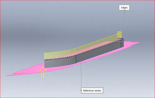
(yellow shaded region represents ruled surface)
SURFACE EXTRUDE and SURFACE SWEEP are applied to develop the side surface part of the superstructure above the ruled surface with the dimension given.
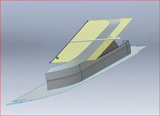
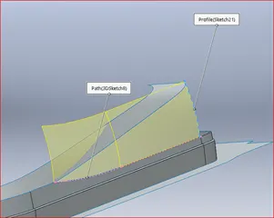
(Surface sweep and surface extrude were seen in yellow shaded region)
PROJECTED CURVE feature is used to create the surface loft between the two curves which is sketched in different planes and projected as one curve using projection curve option.
The 3D sketch is used at most of the times to join the two projected curves to loft them and used as guide curves to define the structure properly.
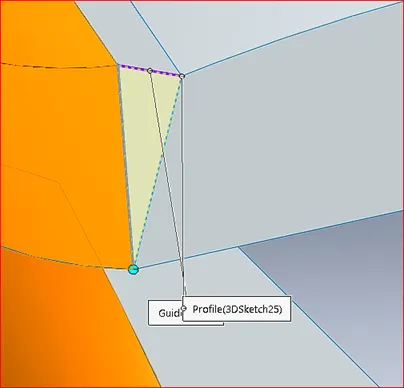
(3d sketch is mentioned in the box)
SURFACE KNIT is done often to combine all surface bodies and knit the small gaps between the surfaces to get a perfect structure and to avoid any flaws due to the gaps formed during the surface works.
The gaps formed during the design could create trouble in making them a solid structure in future. So, surface knit is important feature to be done during surface modelling. (The surface knit will not be done if the gap is too large than the given gap tolerance, <0.1mm gaps will not be knitted. So, the curve projection and surface loft to be done properly before knitting the surface)
SURFACE EXTRUDE is done using the sketch drawn in the midplane and it later trimmed using SURFACE TRIM option to covers the open space which needs to be covered.
Surface trim is the important feature used all around designing the yacht. Here the trim tool is often used tool to remove the unwanted surface portion.
SURFACE EXTEND is also used to extend the surface that already exists. The feature is used in the front portion of the superstructure to extend the surface at front window and bonnet portion and later trimmed to get the complete and perfect structure.
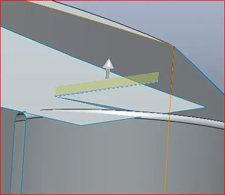
(yellow shaded region creates the surface extend for needed dimension)
After completing the one side of the superstructure modelling the boss extrude feature is used to develop the fountain like structure in the front portion of superstructure. Then the cut extrude and delete face feature also used to transform the solid structure to surface structure.
Finally, the completed surface body to be converted into solid structure using the knit surface feature. The mirroring is done using the midplane or flat solid surface as mirror reference.
The SURFACE OFFSET and THICKEN SURFACE are used parallelly at the front portion of the superstructure to thick the surface body to perform the BOSS EXTRUDE and CUT EXTRUDE feature to make the superstructure more stylish and to get the desired shape. (Boss extrude and cut extrude were not performed in surface body, it can be used only solid body. So, thickening of surface is necessary to perform further modelling of superstructure).
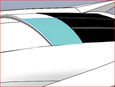
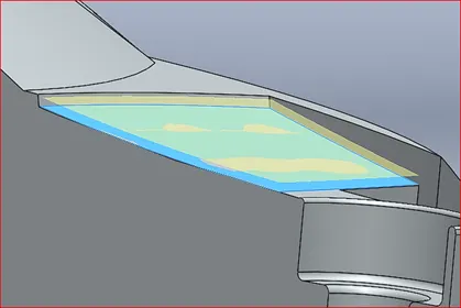
(Surface offset and thicken surface is shaded in yellow region)
SWEEP tool is used to create the holder rods fixed at the superstructure for steady walk and stand during the riding of yacht. The sweep option is used at the front and back of the superstructure model.
SPLIT LINE is a unique feature used to differentiate the faces into two regions for later appearance purpose.
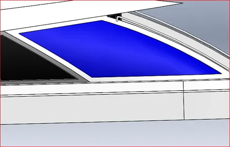
(Split line the region between blue and white region)
FILLET and CHAMFER feature is used at most of the corners and edges of the superstructure after complete modeling the structure to look more realistic and better in rendering the model in future.
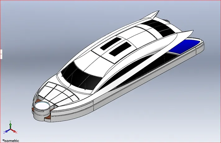
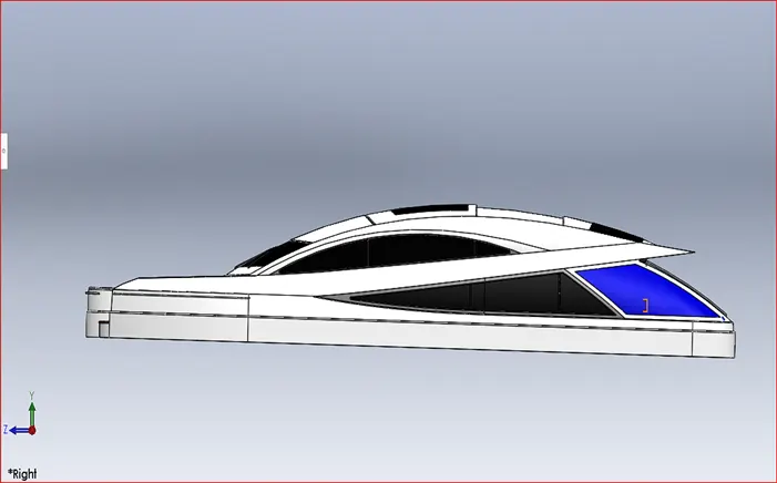
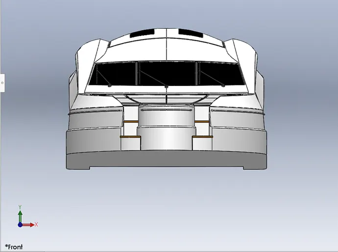
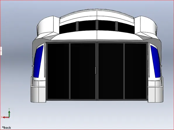
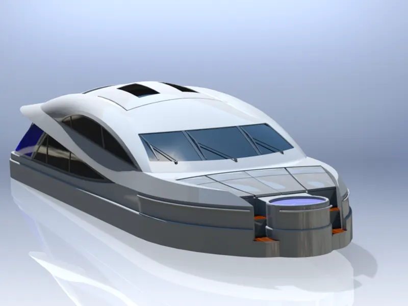
RENDERED IMAGE OF SUPERSTRUCTURE
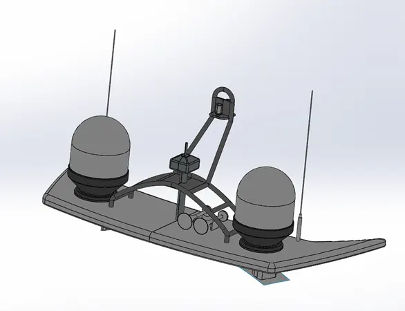
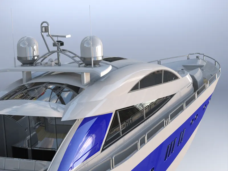
RADAR MAST
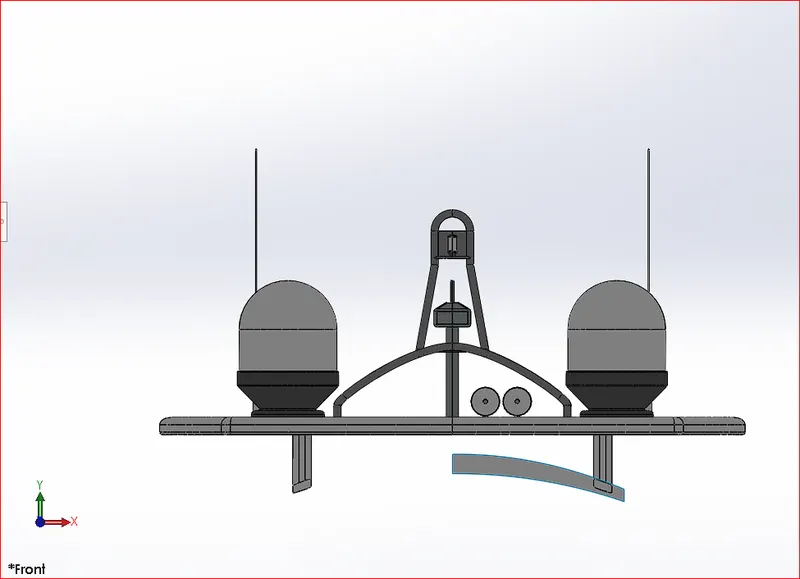
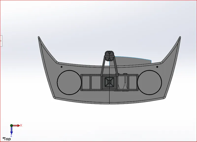
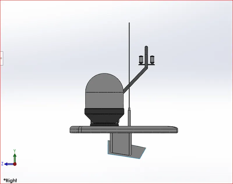
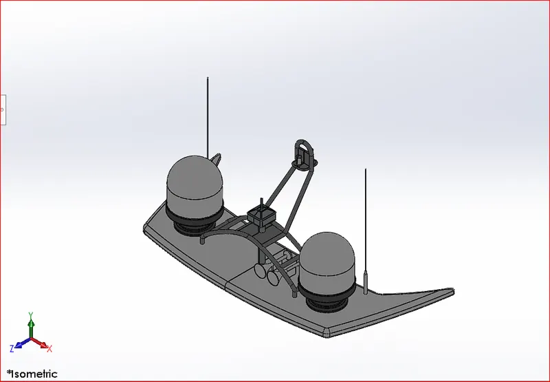
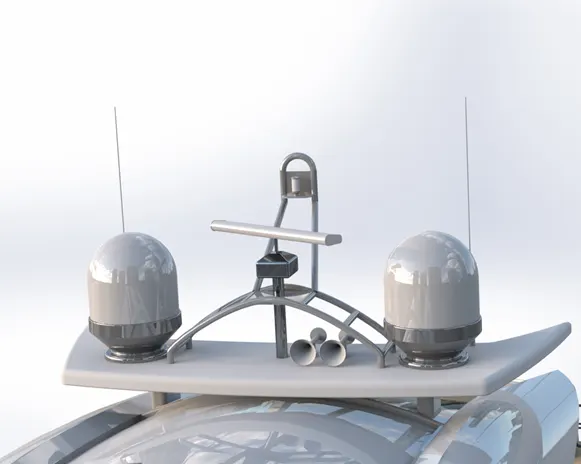
Radar mast is mounted at the top of the superstructure, and it holds the RADAR which guides the yacht during travelling in the sea. The radar mast design needs to be firm and perfect as it needs to withstand heavy weather and wind in the middle of the sea. Here the following feature in solidworks needs to be applied for designing the radar mast.
- Boss extrude
- Revolve
- Fillet
- Sweep
- Mirror
- Curve projection
- Chamfer
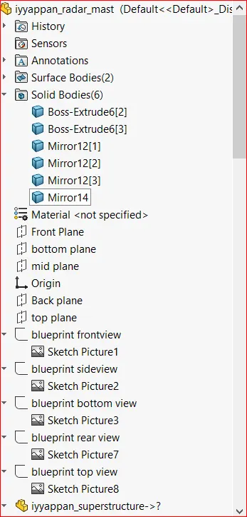
Open the solidworks application. Go to blueprint setup and save file as RADAR MAST. Now go to insert option in the tool bar and insert the surface offset part created during modelling of superstructure. The radar mast is designed over the surface offset so that the part can fit in its own place during assembly without any manual disturbance.
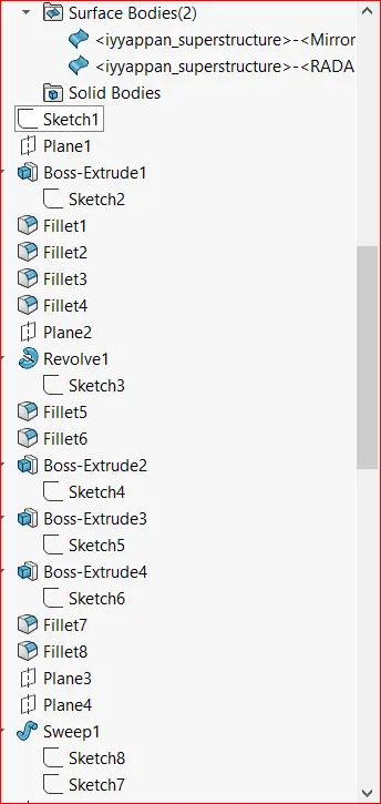
The radar mast part is sketched initially with the reference of blueprints. First, the dome like structure is sketched and developed using REVOLVE feature and base structure of radar mast is boss extruded for required dimension.
Fillet is applied at the sharp corners and edges of the model to give tangent surface for better and original look.
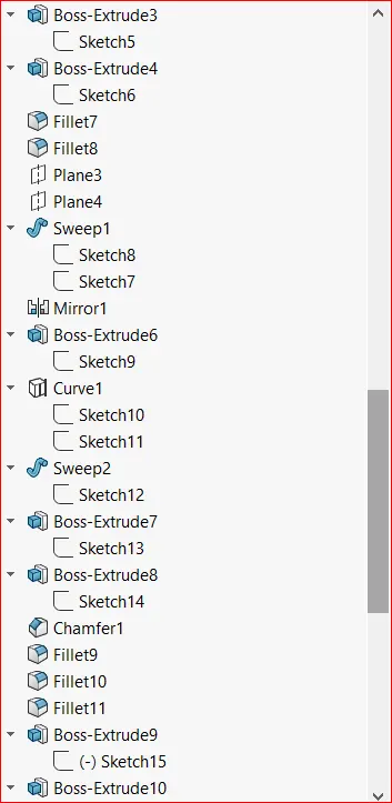
The rod like structures were created by using separate plane with reference to existing structure and the SWEEP feature is used to generate structure in required radius.
The pathway for the sweep is sketched using CURVE PROJECTION drawn in different plane to get the desired 3D sketch for sweep.
The chamfer is applied to the edges of square shaped box using distance-distance method for required dimension.
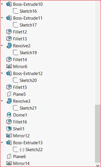
Like other parts, the radar mast is also designed in a way to mirror the twin part from the parent part using the feature MIRROR. The features were separately selected to mirror each part modeled.
RENDERED IMAGE OF RADAR MAST
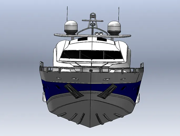
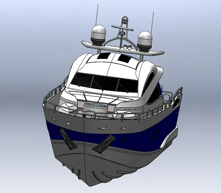
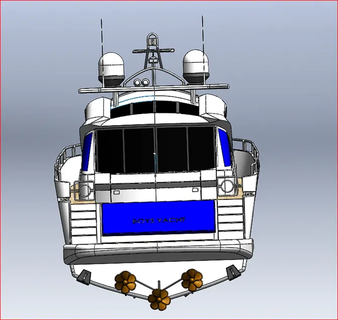
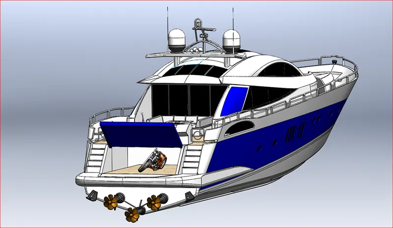
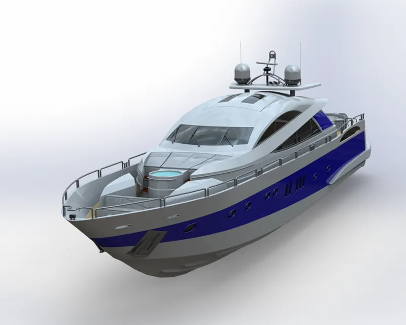
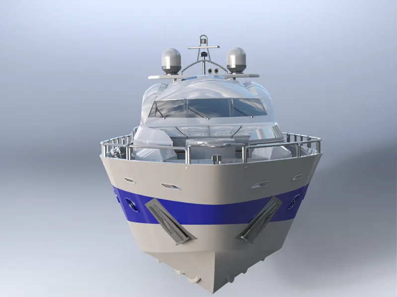
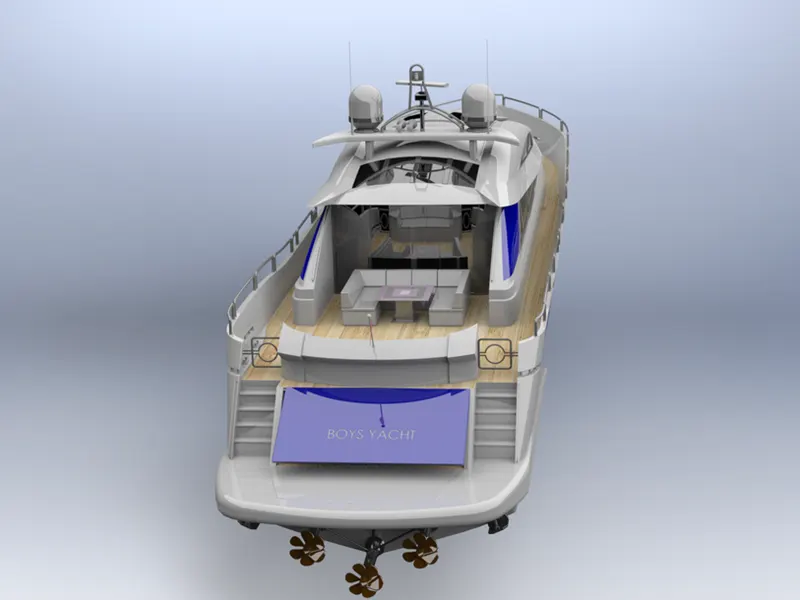
FINAL ASSEMBLY OF YACHT
The assembly of yacht is made simple as we used offset deck surface to design seats and superstructure and offset surface to design the radar mast. The steps involved in assembly of yacht is
- Open soliworks application and go to assembly tab.
- open the hull part first.
- Browse the superstructure part for assembly and click ok. It automatically sit on the deck surface. This is because we designed the superstructure over offset deck surface.
- Browse the radar mast and it automatically sits on the top surface of superstructure that used to design radar mast.
- With the help of concentric and coincident relation assemble the remaining part such as propeller and radar.
- The final assemble of yacht is completed and saved as YACHT ASSEMBLY.
FINAL ASSEMBLY IMAGES OF YACHT
RENDERED IMAGE OF YACHT
RADAR MAST