DESIGN AND ASSEMBLY OF AMERICAN CHOPPER IN SOLIDWORKS 2018
DESIGN AND ASSEMBLY OF AMERICAN CHOPPER IN SOLIDWORKS
(Link for the part files: https://drive.google.com/file/d/1k9Wr77AXi0KtTy6ro1K00TcjJzSm5PV_/view?usp=sharing)
OBJECTIVE
Design and Assembly of an American Chopper (Rt66 Vintage Bike) In Solidworks 2018 by using various tools and features and image rendering the model using solidworks visualization.
INTRODUCTION
Solidworks is an CAD (computer aided design) software used to design any kind of objects in 3D which is extruded from fully defined 2D sketches and geometries. The software was developed by DASSAULT SYSTEMS located in Velizy-Vilacoublay, France. The aim of the software is to creates perfect and detailed solid body, though it has various tools such as surface modelling, sheet metal modelling, photo view 360 and more. It is finest and User-friendly software which allows us to get through the features and tools quickly. Here, we were going to overview and research various tools and features used in designing the vintage American chopper bike.
DESIGN METHODOLOGY
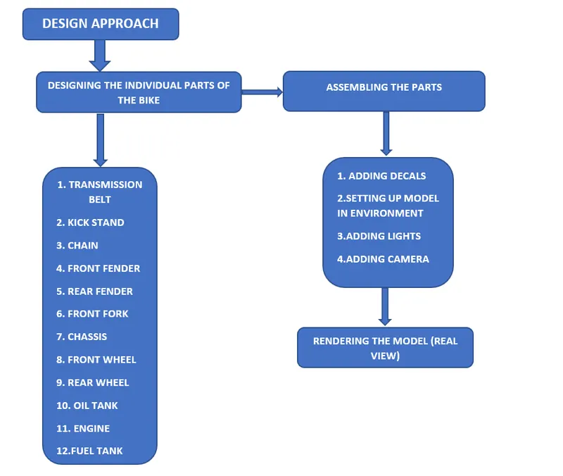
(saving the parts individually every time after done with modelling to re access and rebuild the model in future)
(NOTE: Start the solidworks application and select PART option to design the model needed. After selecting the part, it directs to the window where the FEATURE TREE is seen in the left corner of the window and PLANE is situated in feature tree. Rename the plane according to the convenience to the sketch to be drawn. Finally select the concern plane and start to sketch. This is initial step for every model to be designed in solidworks.)
- TRANSMISSION BELT
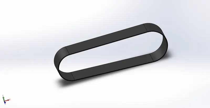
Transmission belt is commonly used in bike to connect gear box driven to rear wheel driven pulleys to take control of speed. In this case the Transmission belt is designed using the following features.
- Boss extrude
- Fillet
First sketch the fully defined entities in Front plane need for the design of Transmission belt
BOSS EXTRUDE- This is commonly used feature in solidworks to convert the fully defined 2D sketched entities to 3D model. Here the feature is used to extrude the portion of sketched entities to generate the required 3D shape of Transmission belt.
(Fully extruded transmission belt from 2D sketch)
FILLET- It is frequently used feature in designing a part in solidworks. It generally works on shaping the corners and sharp edges to give tangency look. It has a several option so that the feature could applied accordingly to the object with desired dimension.
(Close look of filleted edges of transmission belt)
2.KICKSTAND
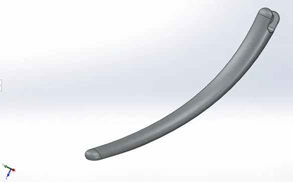
Kickstand is the common part in all the bikes which is used to support the bike to stand in the ground. Basically, the kickstand must be designed in a way has to be firm in the ground. The design must be sure that the kickstand is strong and firm enough and not slippery to the ground.
Features used to design the kick stand:
- Loft
- Dome
- Fillet
- Split
- Boss extrude.
LOFT- It is a handy tool used to join the two ends of the constrained sketches to complete the 3D look. It has a GUIDE CURVE option which enables us to direct the loft in desired directions. In this case we used to loft two ellipse sketches to complete kickstand part model.
DOME- This feature is particularly useful to completes the flat ends of the objects by creating a semi sphere structure to give the perfect look of the design. In this case, two domes feature were added for the real look of the object.
(Dome feature applied to the model is highlighted in red ink)
FILLET- It is frequently used feature in designing a part in solidworks. It generally works on shaping the corners and sharp edges to give tangency look. It has a several option so that the feature could applied accordingly to the object with desired dimension. Here the fillet option is applied to make edges of the kickstand tangent rather than sharp edge. It also gives an reality look to kickstand.
(Image of fillet feature applied to the model is highlighted in red ink)
SPLIT- This option enables us to split the face into two geometries and used to cut the unnecessary region by the sketch drawn on the plane. Here the split option is used to cut the bottom region of the kickstand to stand firm on the ground.
BOSS-EXTRUDE- It is most common feature in solidworks which used to extrude or enlarge the 2D sketch drawn. Simply its feature to convert 2D sketch to 3D model.
(Yellow region is the extruded portion)
3.CHAIN
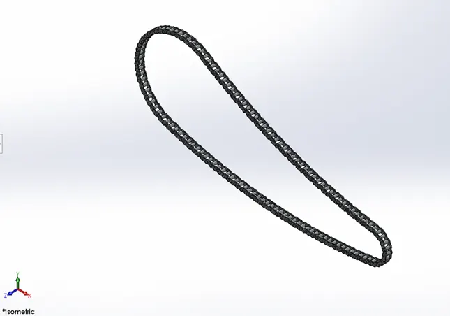
The power transmission chain is the important part in most of the mechanism which is used to transmit power from one part to another. In motorcycle it carries the power produced from the engine to rear wheel used to drive the motorcycle. The features used in chain design after sketches are.
- Boss extrude
- Fillets
- Curve driven pattern.
- Mirror
BOSS EXTRUDE- The inward and outward interlinked block chain mechanism and pins are sketched initially and extruded and follow up the process with the extruded 3D model.
FILLETS- The inward and outward interlinked block chains were applied fillet for the exact look of the model.
CURVE DRIVEN PATTERN- The curve driven pattern is useful to create a multiple number of objects in desired curve direction in this case the interlinked chains already created are driven to the route of curve. The feature is so fast and reliable to create parts like motorcycle chains and more.
(The interlinked chain part follows the curve to pattern)
MIRROR- The Mirror feature is most useful and handy one to create the parts in twin regarding to the plane. It allows to create the exact part from the parent that is already created. Almost it reduces the half of the time in designing the model which already exists and need one.
(The yellow region is the mirror part and blue region is a parent part)
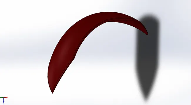
4.FRONT FENDER
The front fender is an outside portion covers over the front tire to protect the bike from throwing sand, mud, stones and other dirt to the rider. In this case Front fender is designed using the following features
- Revolve
- Split
- Fillet
REVOLVE- is an attractive feature in solidworks which is used to create any kind of circular or spherical shaped object using a reference (sketch or plane). The feature is useful because of its wide options to modify the design in desired dimensions.
(Blue one is 2D sketch and yellow region is revolve extension)
SPLIT- In this case, split option is used to cut the unnecessary region and get output extension with desired angle dimension.
FILLET- Here the fillet option is used to make sharp edges and corners tangent with respect to desired fillet dimension.
5.REAR FENDER
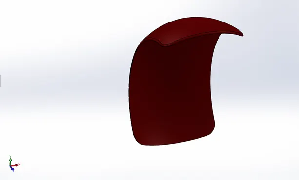
The rear fender is an outside portion covers over the rear tire to protect the bike from throwing sand, mud, stones and other dirt to the rider. In this case Front fender is designed using the following features
- Revolve
- Split
- Fillet
REVOLVE- is an attractive feature in solidworks which is used to create any kind of circular or spherical shaped object using a reference (sketch or plane). The feature is useful because of its wide options to modify the design in desired dimensions.
SPLIT- In this case, split option is used to cut the unnecessary region and get output extension with desired angle dimension.
FILLET- Here the fillet option is used to make sharp edges and corners tangent with respect to desired fillet dimension.
(Same concept is applied over here in rear fender followed by front fender with varied dimensions)
6.FRONT FORK
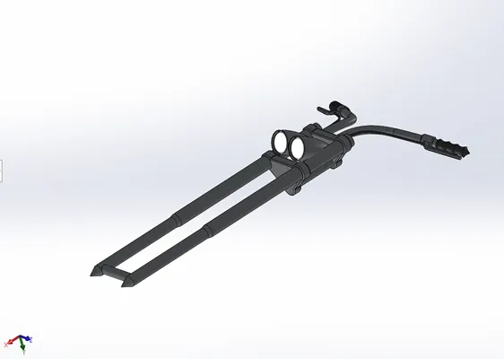
Front fork in the motorcycle is the huge part where it allied with many front parts such as front wheel, handle, headlights and more. It ultimately controls the direction of the bike by the rider. It is especially important for front fork to be stable and should be designed in detail. In this case, to design a front for the following features are used.
- Boss extrude.
- Revolve
- Cut revolve.
- Move/copy body.
- Sweep
- Curve projection
- Fillet
- Dome
- Mirror
BOSS EXTRUDE- After sketching using selected plane, the sketches are extruded to the required dimensions. Here, during boss extrude, make sure to deselect all merge results to ensure the parts are independent.
REVOLVE- here the headlight case is revolved using the revolve feature.
CUT REVOLVE- It is a more flexible option to cut the part/region in revolve direction. Here the revolve feature is used to remove the region around the corner of headlight doom to give a reality look. It is a complex process but made handy in solidworks
(Region around the light highlighted in yellow circle is an revolve cut)
MOVE/COPY BODY- it is one of the new and useful features that we are going through designing of bike still. It works moving or copying body from one place to another with respect to XYZ axis. Here the feature is used to rotate the headlight case to perfectly fits in a location without overlapping with the front fork rod.
(Moving it from blue shaded region to yellow shaded region)
SWEEP- one of the finest features of solidworks which is used to form a hollow and solid pipe in desired dimensions with the help of two sketches (circle and path). It is a time saving features that enables us to instantly design the model to be designed. Here the sweep feature is used to create the handle of the motorcycle.
(Yellow shaded region is the sweep created)
CURVE PROJECTION- it is a noticable feature provided by a solidworks. It is basically working on projecting two different sketches on a two different plane to form a 3D curve. Here the feature is used to create the root or parent curve of the sweep formed for a brake cable part.
(The yellow curve is the projected curve based on two sketches)
FILLET- here is used to create a tangent edges and corners rather than a sharp edges and corners.
DOME- here is used to form the elliptical structure for the headlight doom. It transforms the flat face of headlight to dome formation and giving them a reality look.
MIRROR- as usual does it job of creating the body that already exits and mirrors it from parent part.
7.CHASSIS
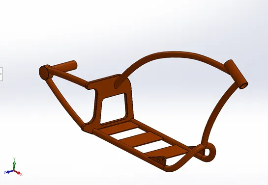
Chassis is particularly important part in all kinds of vehicles and commonly known as skeleton of the vehicle. It holds many components or parts of the body and completes the vehicle structure. Here the features that are used to model a chassis.
- Curve projection
- Sweep
- Boss extrude.
- Cut extrude
- Chamfer
- Dome
- Split
- Revolve
- Fillet
- Combine
CURVE PROJECTION feature in chassis part is important one which follow ups the sweeps in the blueprint fixed. It is applied here to generate the 3D curve which projects two 2D sketches to create the sweep rod all over the chassis part.
SWEEP is formed with the help of projected curve by drawing circle to form sweep at required dimension in the end curve.
BOSS EXTRUDE is applied to build the flat part of the chassis which must hold the oil tank and essentially the engine component. These are sketched and extruded from it.
CUT EXTRUDE is used to cut the holes in the clamps designed in the bottom of the chassis to fit the engine component firmly to the chassis.
CHAMFER is a feature works nearly to the work done by fillet, but it forms a flat portion by removing the extra portions in the edges or corners to get a desired shape. Here the chamfer is applied to form the calculated view.
(Yellow region is preview which is about to remove portion in right side and forms a flat surface)
DOME option is chosen here to make the clamps to look real and its dynamic feature in all around the design of motorcycle when it comes to real view.
SPLIT feature is used to remove the unwanted portion of the design structure which must cut exactly to avoid any mess. Here the split feature is used to remove the excess of sweep formed beyond the geometric calculations.
FILLET here is used to make the edges and corners of flat portion of the chassis to look tangent and giving them a perfect look.
COMBINE is cool feature which is used to combine the separate multiple bodies into a single body and forms and requires shape needed.
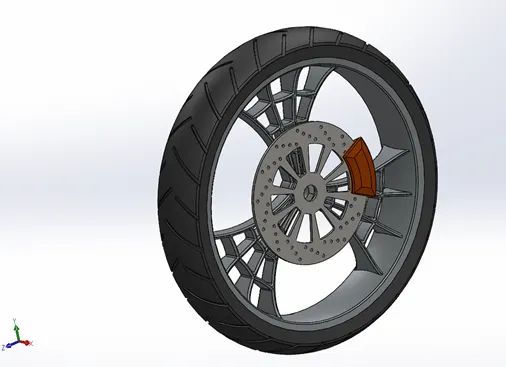
8.FRONT WHEEL
Wheels are the major component of the vehicle which it sustains the entire loads and carries it. The important features that are used in wheel parts are listed.
- Revolve
- Fillet
- Boss extrude
- Cut extrude
- Chamfer
- Cut revolve
- Circular pattern
REVOLVE is the common feature in designing the wheel part. It gives the actual shape of the wheel initially by revolving the sketch.
FILLET is applied to the sharp edges of the revolved part to get a fine look of the wheel rim.
BOSS EXTRUDES are used in various location of the wheel like rim, caliper, rotor and more to generate the required component.
CUT EXTRUDE is used here to remove the regions in rotor, rim to get an actual part design and shape to fit with one another.
CHAMFER feature is applied to rotor and the caliper around its edges to generate the required view of the component.
CUT REVOLVE is used here to cut around the corners of the rim to remove the extrudes to provide the stylish look of the wheel.
CIRCULAR PATTERN is one of the handy tool in solidworks used to get multiple work done in one option also reduced the time to get done with the design of the part. Here the pattern is applied for cut extrude in rotor,rims, and cut extrude in tires to get an required output.
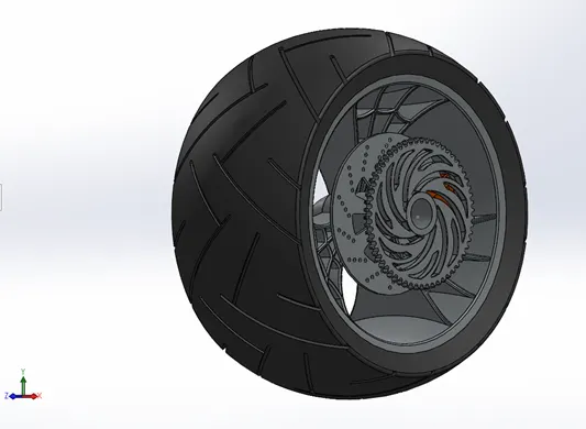
9.REAR WHEEL
Wheels are the major component of the vehicle which it sustains the entire loads and carries it. The important features that are used in wheel parts are listed.
- Revolve
- Fillet
- Boss extrude
- Cut extrude
- Chamfer
- Cut revolve
- Circular pattern
REVOLVE is the common feature in designing the wheel part. It gives the actual shape of the wheel initially by revolving the sketch.
FILLET is applied to the sharp edges of the revolved part to get a fine look of the wheel rim.
BOSS EXTRUDES are used in various location of the wheel like rim, caliper, rotor and more to generate the required component.
CUT EXTRUDE is used here to remove the regions in rotor, rim to get an actual part design and shape to fit with one another.
CHAMFER feature is applied to rotor and the caliper around its edges to generate the required view of the component.
CUT REVOLVE is used here to cut around the corners of the rim to remove the extrudes to provide the stylish look of the wheel.
CIRCULAR PATTERN is one of the handy tools in solidworks used to get multiple work done in one option also reduced the time to get done with the design of the part. Here the pattern is applied for cut extrude in rotor,rims, and cut extrude in tires to get an required output.
(The methods of designing rear wheels are same as front as it differs by dimensions)
- OIL TANK
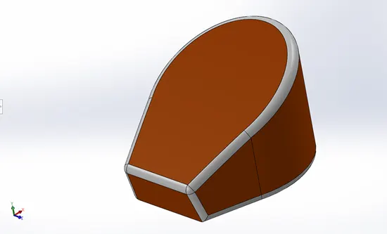
Oil tank generally used to store the oil feeds to the engine parts for lubrication. The design of oil tank includes the following features.
- Boss extrude.
- Fillet
- Combine
- Shell
BOSS EXTRUDED the sketch drawn in the concerned plane with the desired dimension.
FILLET is applied after extruding the sketches to make the edges and corners tangent.
COMBINE feature is applied in this part to combine two boss extrude bodies to generate a desired shape of the oil tank.
(two boss extrudes combined shown in blue)
SHELL is an extremely useful feature that allows us to remove the inner regions of solid bodies and makes it hollow. It creates open shell and closed shell as well. Here the option is used to make the closed shell.
(the hollow region is viewed through exploded option)
11.ENGINE
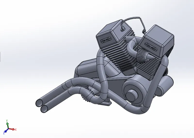
Engine is the important component and also called as Heart of the vehicle where it produces required power to drive a vehicle. Engine is most complicated component consists too many fixtures and parts. While designing the engine, it is important to choose the dimensions and location to connect other sub parts of the engine. In this case the following features are used to design an engine component after sketching follows.
- Boss extrude
- Fillet
- Revolve
- Circular pattern
- Dome
- Cut extrude
- Chamfer
- Linear pattern
- Mirror
- Split
- Sweep
- Combine
- Projected curve
- Composite curve
The layout of engine is drawn in 2D sketch option and BOSS EXTRUDE the sketch for the rough look of an engine. After extruding the sketch, the FILLETS were applied to the edges of the faces. The shaft of the pulleys are created using REVOLVE feature and the CUT EXTRUDE option is applied to cut the holes of the shaft to give real look. Finally CIRCULAR PATTERN is used to create number patterns of features or bodies created. The DOME feature is used in end face of motors to give original look. The chamfer is applied at top of the engine component to get the requires shape and the chamfer option is widely use here to get the exact look need for engine. The outside portion of the engine bore is extruded and MIRRORED from the parent part. The SPLIT option is used to cut the unwanted portion of the engine component. The exhaust pipe is essential subcomponent I engine part and it is designed using the SWEEP feature. The PROJECTED CURVE is used to design the exhaust part and its path to sweep. There are multiple number curve entities are sketched in engine part. All these curves are joined into a single curve by COMPOSITE CURVE feature. Finally, the COMBINE feature is applied by selecting all separate parts and combining them together by the COMBINE feature.
12.FUEL TANK
Fuel tank is common part in all kinds of vehicles running by fuel. Following that, the final part of the motorcycle includes the fuel tank where the only part focusing on surface design rather than other components of the bike. The features used to design the fuel tank followed by
- Surface sweep
- Surface trim
- Projected curve
- Surface loft
- Boundary surface
- Mirror
- Surface knit
- Split line
- Surface extrude
- Fillet
- Composite curve
- Cut sweep
- Shell
SURFACE SWEEP- It is most useful feature in surface tool which is used to sweep the surface using the sketch drawn in the mid plane of the part. Also, if forms an upper outer surface of the fuel tank.
SURFACE TRIM- This is one of the essential features to trim the surface or removing it from the part design. Here the surface trim is used to remove the extra portion in the sweep surface to get the desired shape of the fuel tank and give them a stylish look of the motorcycle.
(Violet region is a portion about to trim)
PROJECTED CURVE- Two different sketches on a two different plane are projected as single curve and it is used to loft the side portion of the tank after trimming the surface. Aftmost, it forms the one side of the tank.
SURFACE LOFT- The most used feature across designing of the fuel tank. It helps to form a surface extrude between two sketches and projected curves. The design of tank is furnished with this feature.
BOUNDARY SURFACE- It is used to form the surface design in complex shapes like tangent and continuous curves used in design. It is the more flexible feature in lofting surfaces.
(Yellow region is the boundary surface loft)
MIRROR- As mentioned in previous parts, the mirror option is used in the surface design too. It forms the mirrored image of parent image. The first part of the fuel tank design is done with loft tools, and the part is mirrored using the reference plane and completes the part design.
SURFACE KNIT- It is an unique feature used to merge two or more faces or surfaces to join together to forms an single body and also creates an solid body where it is necessary. In this case it is used to bind the surface portions to form a solid body for sweep cut to fit in assembly and finally made hollow inside using shell feature.
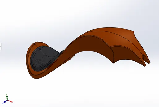
SPLIT LINE- In designing the fuel tank, seat is designed and combined with the tank, so the entities of surface edges are offset and differentiated from the fuel tank. The closed entities then extruded to form a seat.
SURFACE EXTRUDE- The entities sketched for the seat portion then extruded using surface extrude feature situated in the side bottom of the fuel tank in limited space.
(Yellow shaded region is the surface extruded portion)
FILLET- This is quite common feature added to all the parts designed to give the original look by making the edges and corners tangent. Here the fillet is applied around all the part of the fuel tank.
COMPOSITE CURVE- It’s a unique feature used to join or merge the curves, entities or sketched geometry into a single curve. During the sweep or loft the different curves sketched are joined together for single curve. Here the composite curve is used make projected curves together.
CUT SWEEP- To place the fuel tank in a chassis it needs some place to fit properly at the assembly. So, the cut sweep feature is applied to cut the region through the tank to form an sweep space to sit in a chassis during assembly. The is applied in bottom portion of the tank.
SHELL- Finally shell feature is used to make the inner portion of the fuel tank hollow after the sweep cut into the part.
ASSEMBLING THE PARTS OF AMERICAN CHOPPER
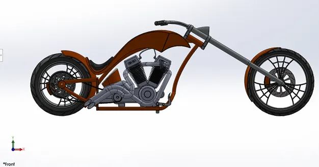
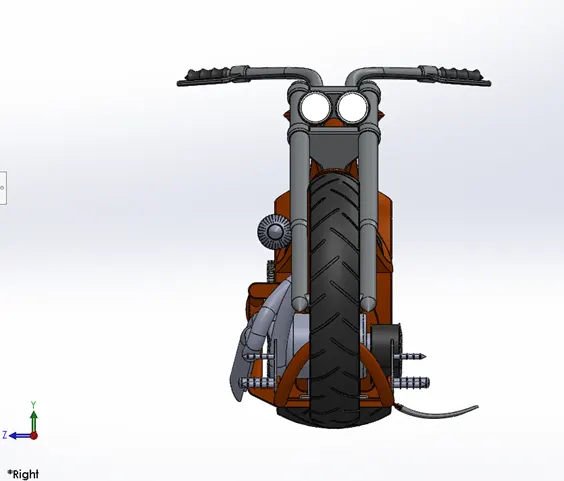
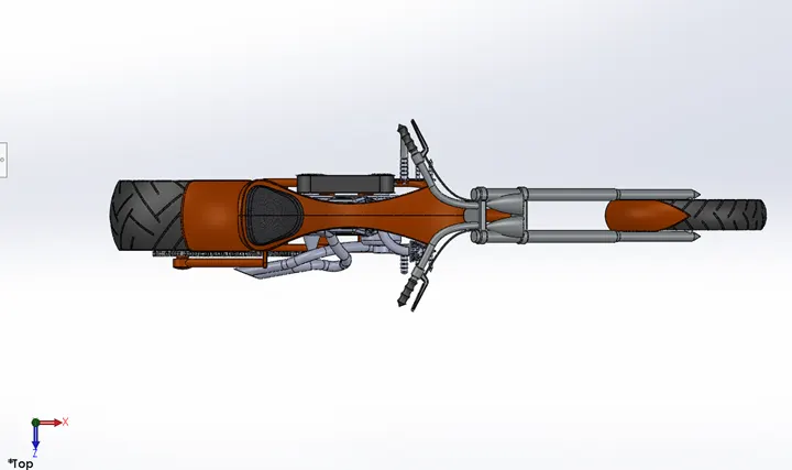
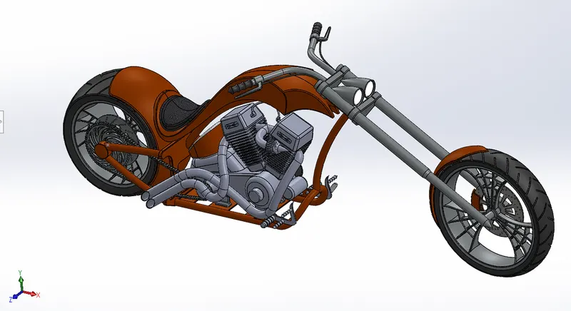
Assembling of bike starts after completing the design of individual parts. In the assembly, the chassis of the bike is mounted initially, and other parts are assembled with relation to the planes of Chassis to follow up. The image of completely Assembled bike is attached below.
FRONT VIEW
SIDE VIEW
TOP VIEW
ISOMETRIC VIEW
ADDING DECALS TO THE PARTS
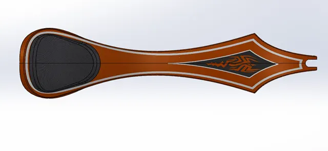
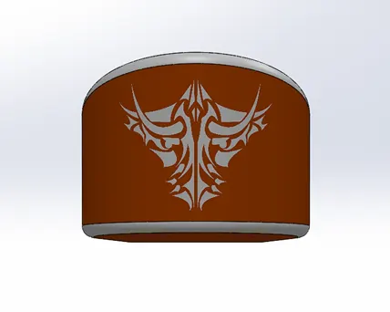
To give more realistic look, the decals were added to fuel tank, rear fenders and the oil tank parts individually after assembling the bike. The image after adding decals is attached below.
DECALS IN FUEL TANK
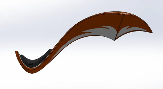
DECALS IN REAR FENDER
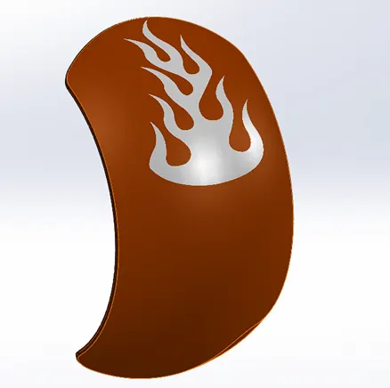
DECALS ADDED TO OIL TANK
ADDING ENVIRONMENT, LIGHTS AND CAMERAS
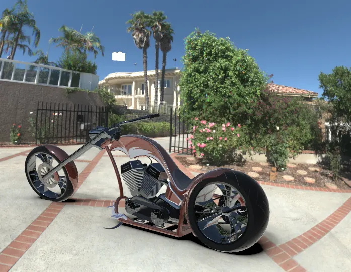
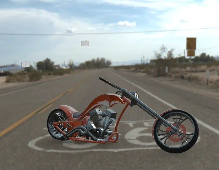
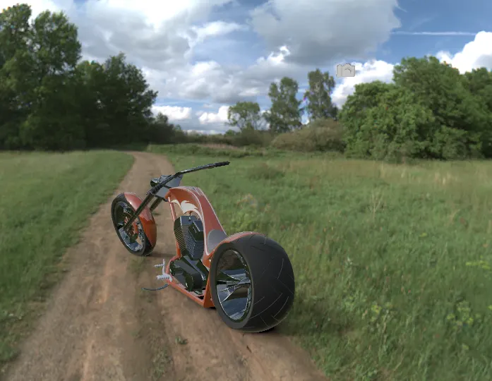
After adding the decals, its time for the chopper model to setup in an environment. Adding lights under different conditions and setting up the model in different camera angle are done for the convenience of the Designer. There are lot of Environment, lights and camera options are available in Solidworks according to the character of the model. The following images are attached in different camera angle and lights.
RENDERED IMAGE OF MODEL AFTER SETTING UP IN ENVIRONMENT, ADDING CAMERA VIEWS, LIGHTS IN PHOTOVIEW 360.
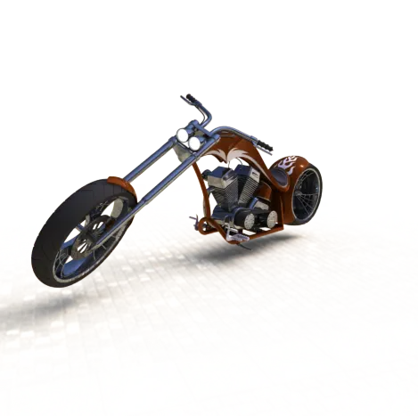
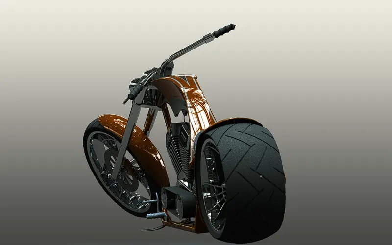
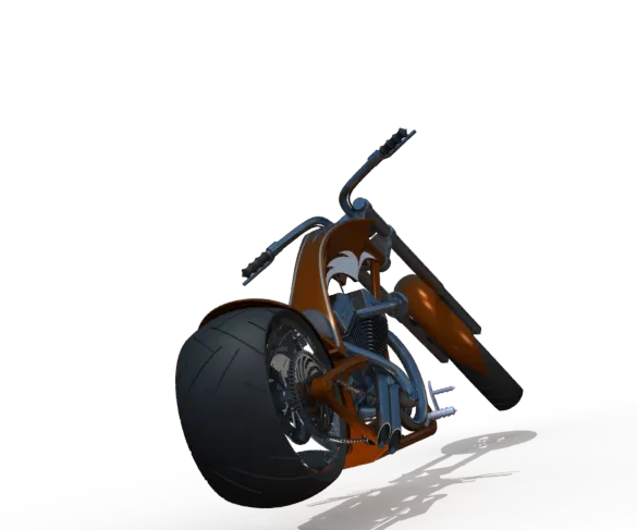
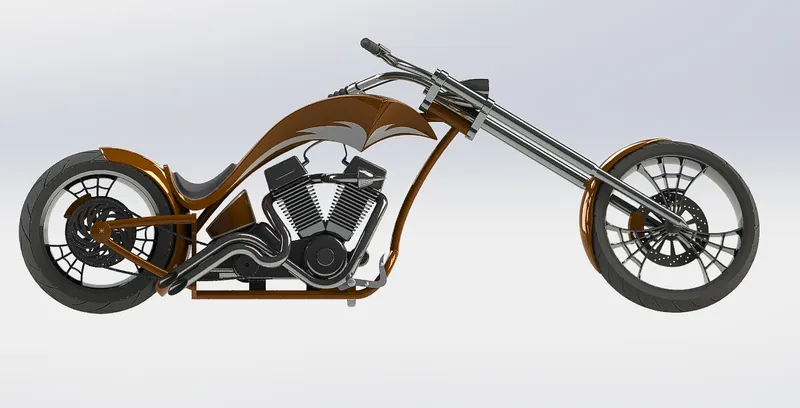
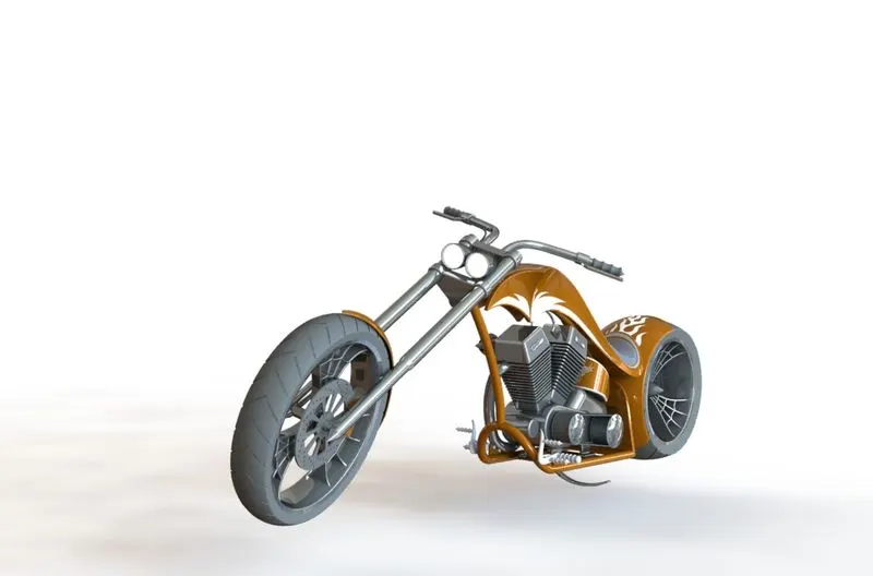

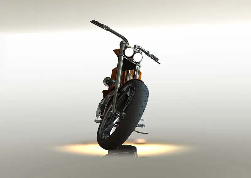
(DUE TO THE PROBLEM IN SOLIDWORKS VISUALIZATION APPLICATION ONLY ABLE TO UPLOAD PREVIEW IMAGES)
SYSTEM SHOWS ERROR RENDERING THE MODEL. HERE ARE FEW PREVIEWS OF MODEL.
CONCLUSION
In the overall project of designing the American chopper bike, I had learned many unexplored features and tools which needs to be applied wherever necessary. From sketching to rendering the final image of the bike, the detailing and steps to generate the perfect output was challenging and faced many mistakes and flaws which directs me to the complete designer of the project.
THANK YOU!
REGARDS
Iyyappan k