Advanced Sheet Metal Design Using NX Cad Challenge_5_Odd Shaped Enclosure
DESIGN OF AN ODD SHAPED ENCLOSURE USING NX
OBJECTIVE
To create an odd shaped enclosure using the sheet metal features in NX.
INTRODUCTION
Software
Formerly known as Unigraphics, NX is an advanced CAD/CAM/CAE owned by Siemens PLM Software. It utilizes a parasolid geometric modeling kernel and is mostly used when advanced modeling features are required in a product. The ownership of the software belongs to the American Software company, Siemens (owned since 2007).
The NX 10 version has been used in this project.
Sheet metal
One of the fundamental forms used in metalworking, sheet metals are thin pieces which can be cut and bent into a variety of shapes. Thickness can vary from 0.5mm to 6mm. This process has been employed in this project to ensure a realistic approach in designing the part.
Target Model
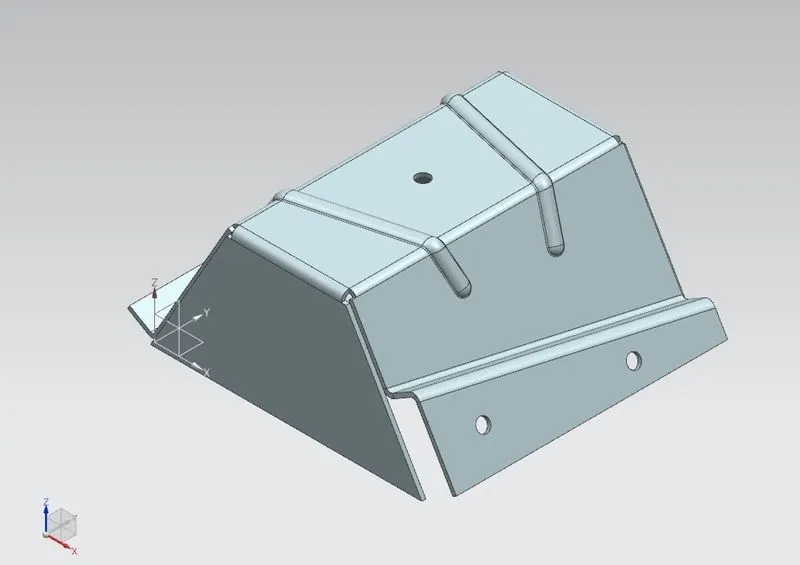
The target model for this project is an enclosure with irregular bends on the side faces.
DESIGN PROCESS
Process Flowchart
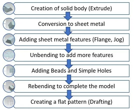
Features and Tools used
- Sketch: Line, Point
- Sheet metal (Basic): Sheet metal from solid
- Bend: Flange, Jog
- Design Feature: Extrude, Hole
- Punch: Bead
- Form: Unbend, Rebend
- Flat Pattern
- Drafting: Base View
DESIGN PROCESS
Units
All dimensions associated with this project are in Millimeters.
Process Description
1.Designing the solid body
- A base sketch (Trapezoidal shape) was created in the XZ plane as a target for the solid body extrusion. The sketch was then extruded in the Y direction using the Extrude feature to create the solid body.
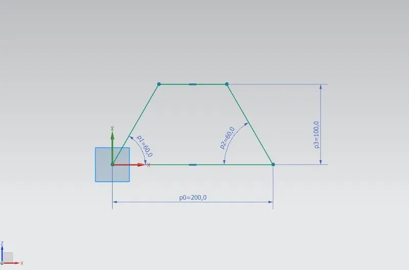 Fig1: Base sketch for the solid body
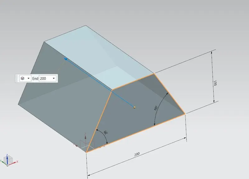 Fig2: Extrude Feature
- To create the enclosure, this solid body needed to be converted into a sheet metal part. To achieve this, the Sheet Metal from Solid feature was used. This feature wrapped a sheet metal component around the solid body to form the required shape. The extruded body was then hidden from the feature tree to focus the work solely on the sheet metal component.
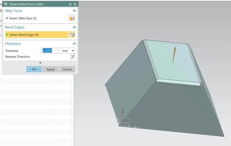 Fig3: Sheet metal wrapped around the solid bodyT
- To create the first modification, the bottom edge of the left face was chosen and the Flange feature was applied to it.
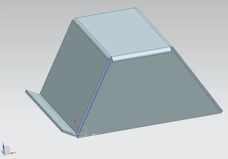 Fig4: Flange feature
- An inclined line sketch was created on the right face to act as a jog line while creating the Jog feature.
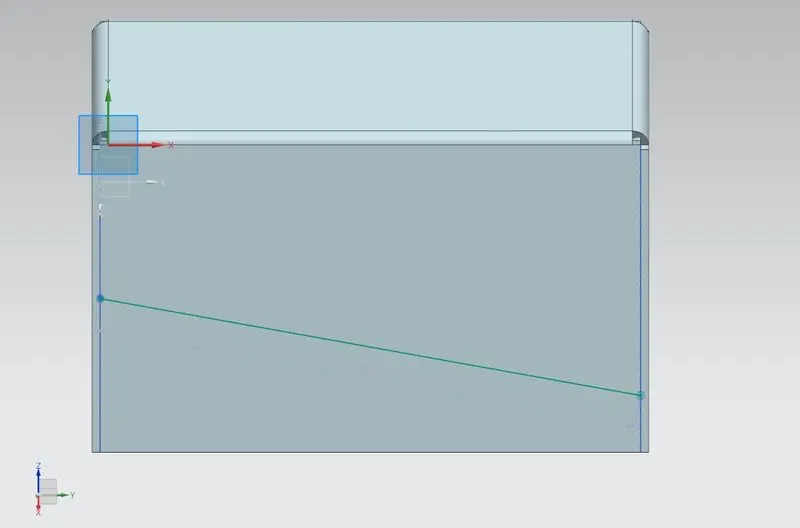 Fig5: Jog Line (Sketch)
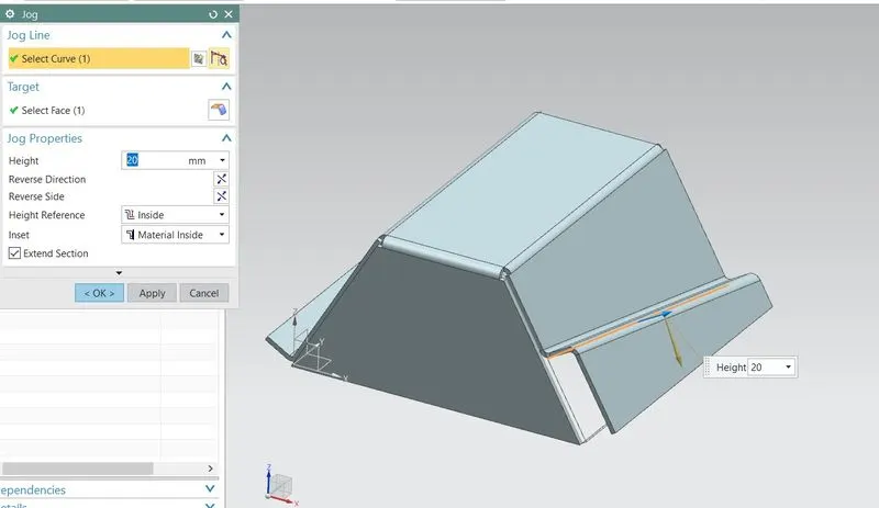 Fig6: Jog feature
- The above mentioned features (Flange and jog) were exclusive to the side faces. To create features common to both, spread through the top face, the model needed to be spread out. To achieve this the Unbend feature was used to remove all the bends and create a flat sheet model.
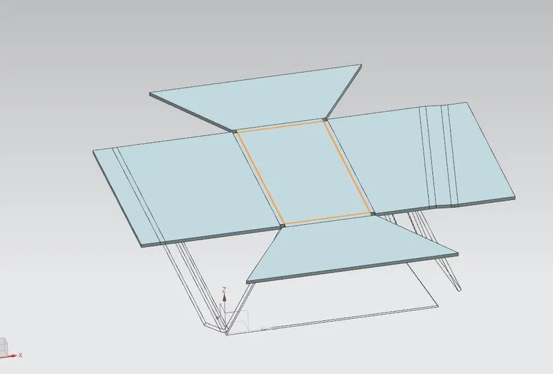 Fig7: Unbend feature
- A Bead feature was created on the top face using two non parallel line sketches starting from the left face and ending on the right face thereby including the top face as well.
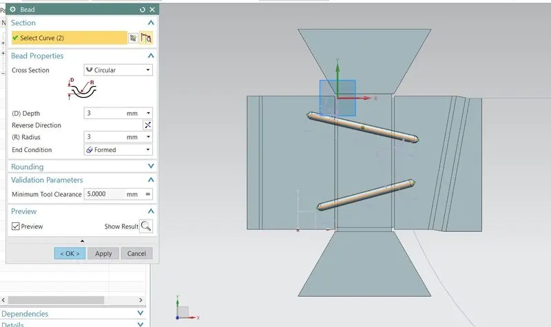 Fig8: Bead Feature
- By specifying points (sketches) on the top unbent faces (including the side faces) a few holes (simple holes) were created using the Hole feature.
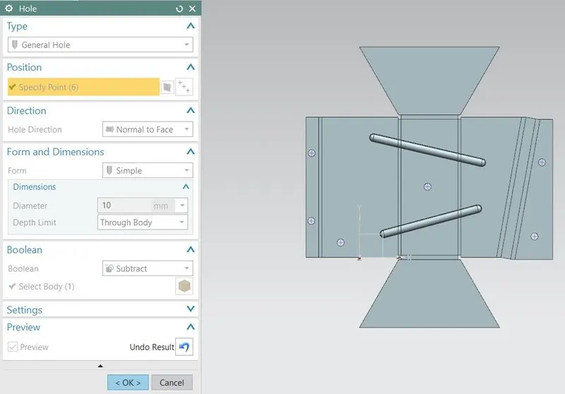 Fig9: Hole Feature
- To revert the model back to its original form, the Rebend feature was applied.
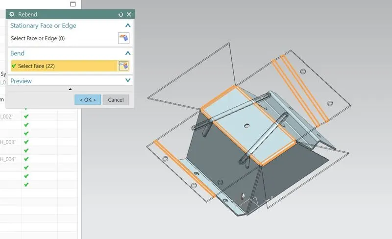 Fig10: Rebend feature
- To create a separate configuration of the part in the flattened form, the Flat pattern feature was used with the positive X direction as the orientation.
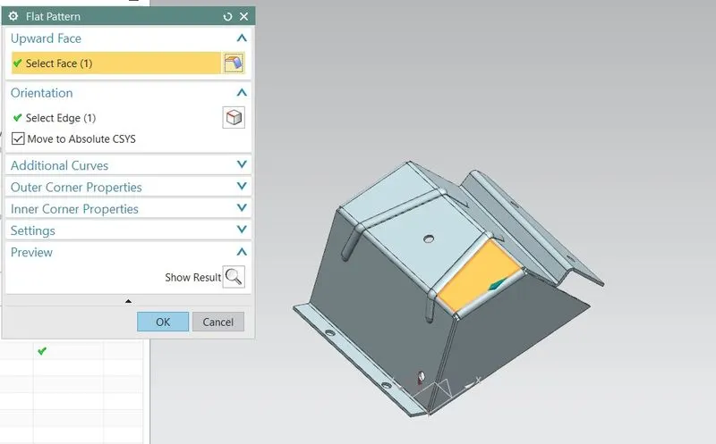 Fig11: Flat Pattern feature
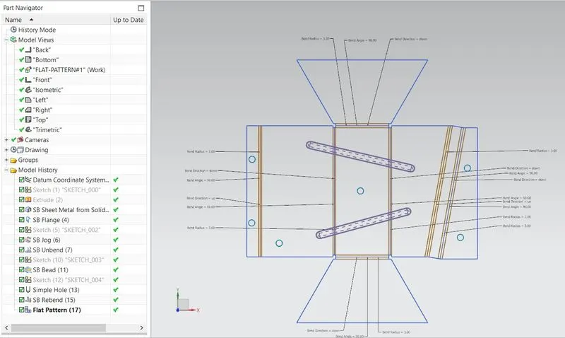 Fig12: Flat Pattern View
STANDARD VIEWS
TOP (Fig13)
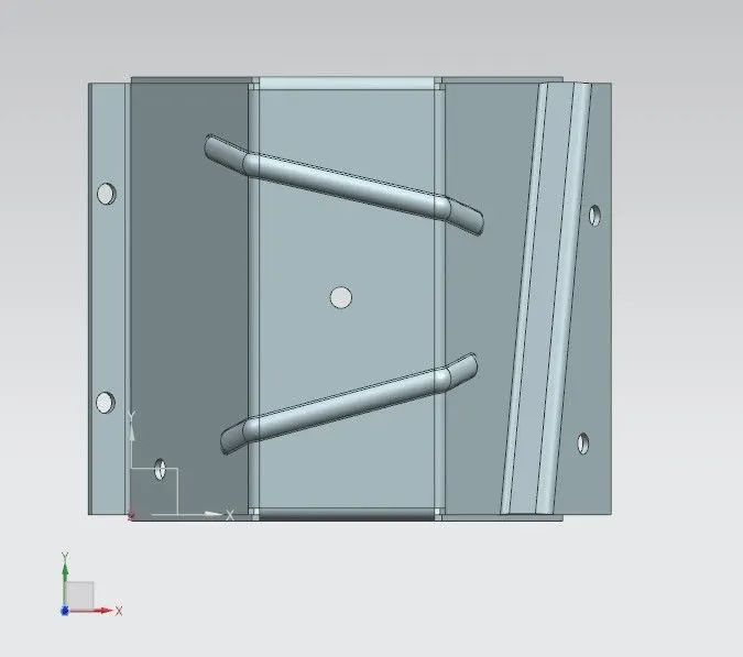
FRONT (Fig14)
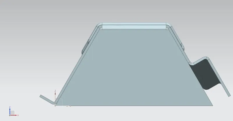
SIDE (Fig15)
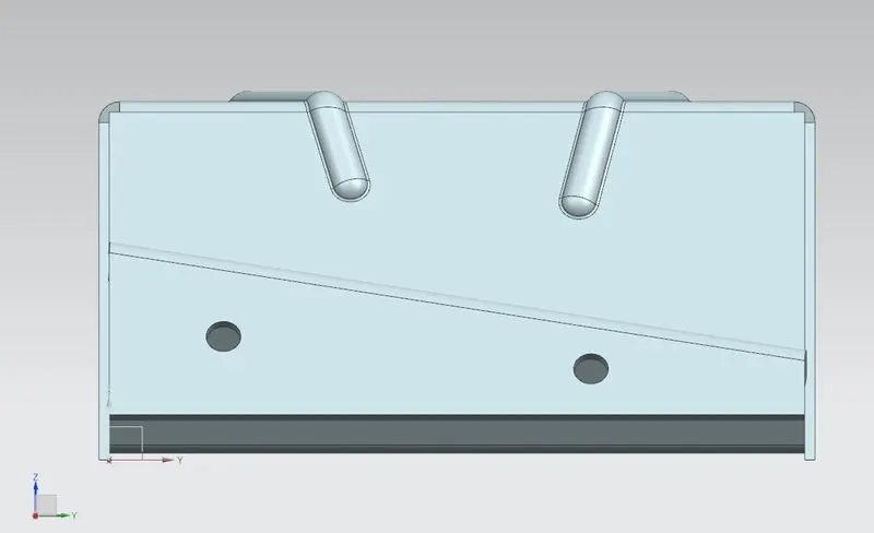
ISOMETRIC (Fig16)
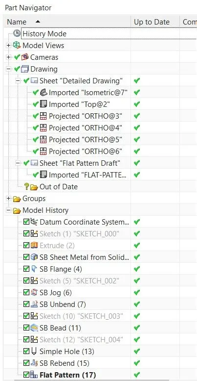
FEATURE TREE (Fig17)
DRAWINGS
By changing the application from Sheet Metal to Drafting the drafts of the model were created. The Base View feature was used to select the view to be used in the model.
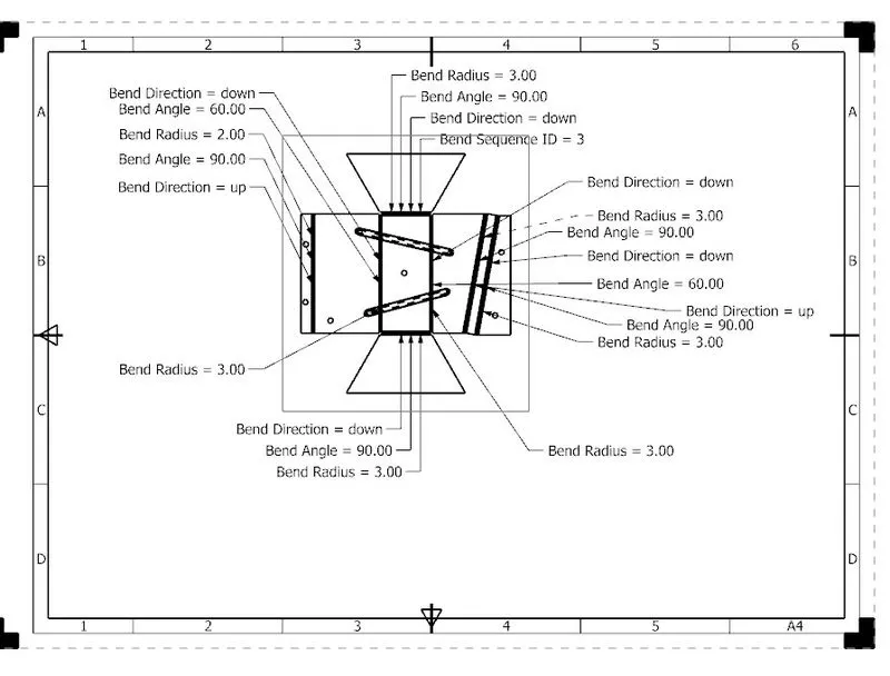 Fig18: Flat Pattern Drawing
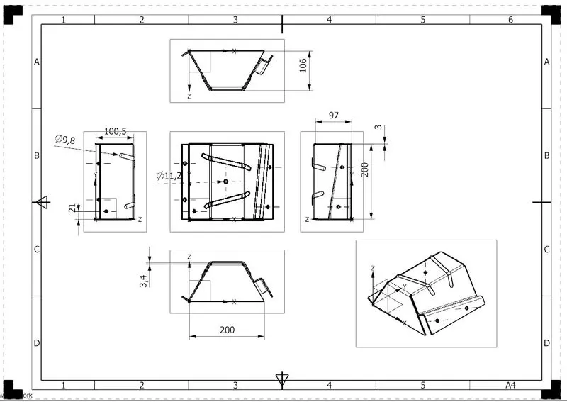 Fig19: Detailed Drawing
CONCLUSION
The odd shaped enclosure was successfully modelled using the appropriate sheet metal features in NX. The choice of an irregular geometry helped to understand the powerful sheet modelling tools offered by this software.