Project - Position control of mass spring damper system
Q1=Obtain the transfer function of a mass spring damper system and use it in the model. Add a PID controller to adjust the force on mass so that its position follows a reference signal.
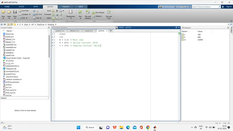
Take m = 3.6; %kg k = 400; %N/m c = 100; %Ns/m
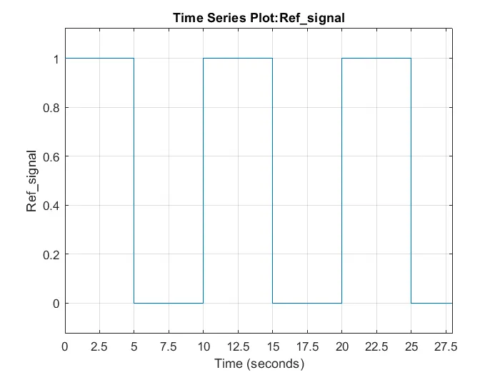
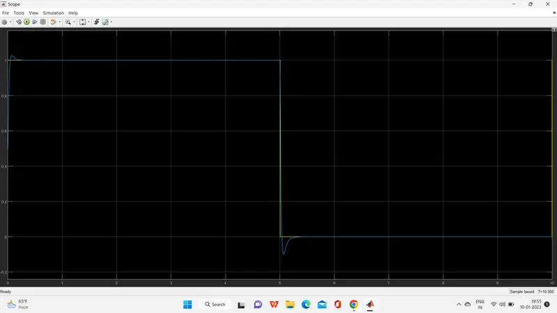
The reference signal is shown in the following figure.
Ans=
mass spring damper system-
There are three types of components in a spring mass damping system, the first component is the spring, the second component is the mass, and the third component is the damping.
spring=Springs store energy and release it later
mass=It is a property of any material which is called mass.
damping=Damping is a type of fueled spring that stores energy and then releases it slowly.
And spring-mass and damping, the combined of these three is called spring-mass typing system.Spring-mass-damper systems can be found in many mechanical systems. One common example is the suspension of a car. The car itself is the mass; it is suspended by an elastic spring. A damper (the actual shock absorber) prevents oscillations. The basic schematic of a spring-mass-damper system
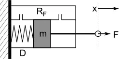
MATLAB may be used to run simulations of such models. As well as engineering simulation, these systems have applications in computer graphics and computer animation.
according to Newton’s second law (F = m*a) related for Mass Spring Damper System-
F = Resultant of all the forces
m = Mass
a = Acceleration
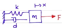
where
k= is the spring stiffness
d= is the damping coefficient
The above system is in a state of rest. Let's consider a moving Mass Spring Damper System to see forces act during motion. What are the forces acting if the system is moving?
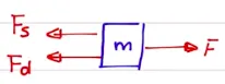
Expression for Spring Force and Damping Force-
(spring force)Fs = k*x ----(1)
(Damping force)Fd = d*(dx/dt) ----(2)
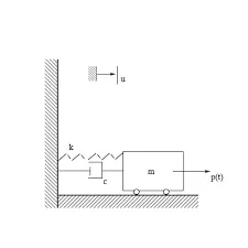
Simulink Model=
using component
1-Pulse Generator
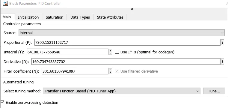
2-PID Controller
3-Transfer Function
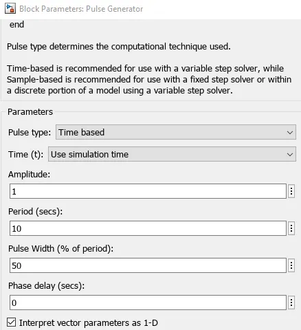
1-Pulse Generator
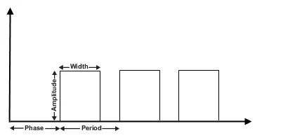
The Pulse Generator block generates square wave pulses at regular intervals. The block waveform parameters, Amplitude, Pulse Width, Period, and Phase delay, determine the shape of the output waveform. The following diagram shows how each parameter affects the waveform.
PID Controller-
PID control respectively stands for proportional, integral and derivative control, and is the most commonly used control technique in industry.
Transfer Function-
The Transfer Fcn block models a linear system by a transfer function of the Laplace-domain variable s. The block can model single-input single-output (SISO) and single-input multiple-output (SIMO) systems.

After running=
1=Pulse Generator
2=PID Controller
scope=
program=
Simulink Mode=
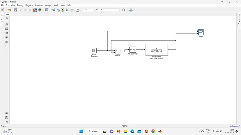
A Pulse Generator block is used as a reference Force input signal for the system. A Transfer function block is used for the implementation of the Mass Spring Damper system. The systems-derived equation in the Laplace transform is used in the transfer function. Variables of the same are defined through a Matlab script. The output of the transfer function is the displacement of the system, which is then fed back to the PID Controller as an error signal after subtracting it from the reference signal. Using a Controller the system throws the best tracking response.
PID Tuner
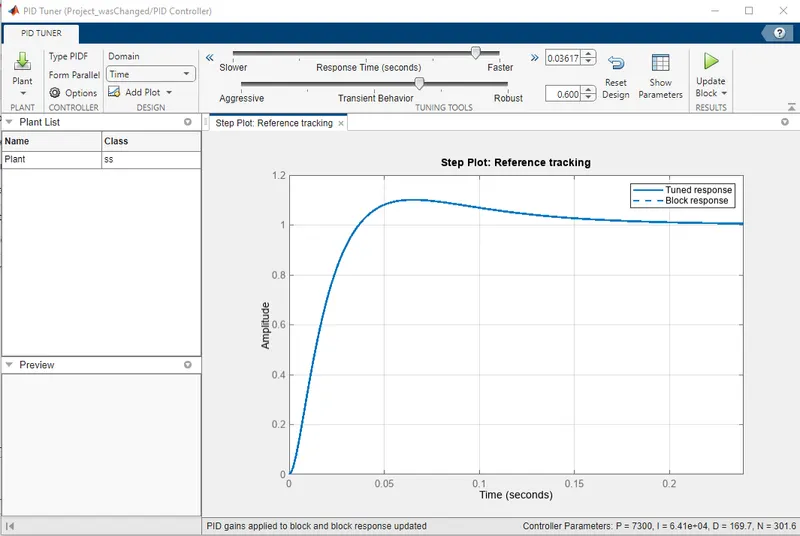
Below is the Tuned response of the PID Tuner. Response Time is increased manually for the best outcome and the same response is upgraded for the system using the Update Block option.