Project 1
Project 1= deals with the development of a forward energy-based fuel consumption model of a conventional vehicle.
The main goal of this project is to get familiar with the modeling process, writing scripts in Matlab, modeling in Simulink, analyzing data and generating plots.
Aim:-
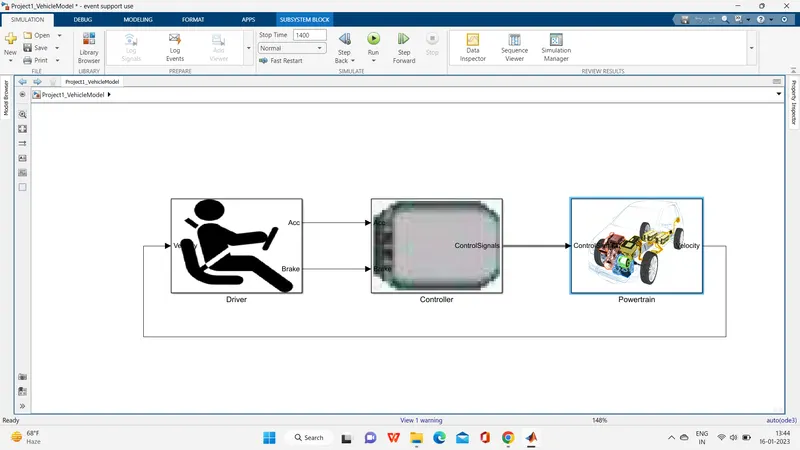
1] Build Simulink model using blocks and complete the vehicle model.
2] Writting scripts in MATLAB to load all the variables required for running the Simulink model.
3] Tabulate the fuel economy numbers (kmpl) for UDDS and HWFET cycle.
4] Plot the time trace for engine, transmission input, transmission output and wheel speed on one plot.
5] Plot engine torque, engine power, fuel rate and fuel consumption using subplots.
6] Plot accelerator and brake pedal, gear command, vehicle desired and actual speed, vehicle distance using subplots.
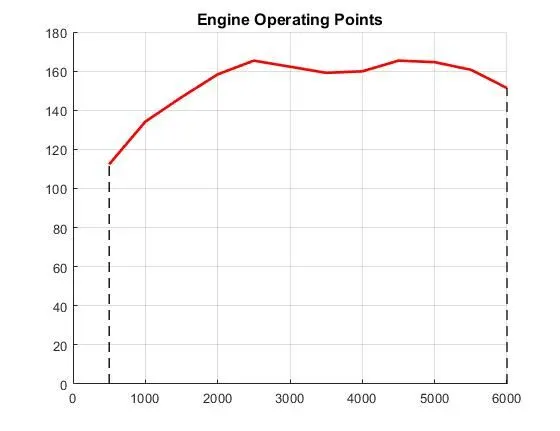
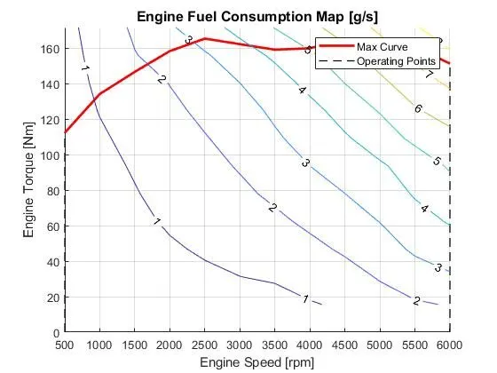
7] Plot the engine operating points on the engine fuel map.
8] Generate the plots for both drive cycles.
9] Study of Conventional vehicle simulink model and creates graphs.
Conventional Vehicle:-
The main function of the conventional is to convert the power generated by the engine into mechanical power using full power. The main function of the transmission is to distribute the energy generated by the power to the wheels.Conventional vehicles use an internal combustion engine fueled by gasoline or diesel to power the wheels. In this the heat engine uses the principle of heat release through combustion of a fuel with an oxidizer in a combustion chamber to create expanding gases which pushes against a piston creating forcce and torque output.
In this vehicle engine converts chemical energy stored in the fuel into heat which is used to produce useful work. Typically use fossil fuels like petroleum (petrol and diesel).
The most popular type of engine is used in this system is 4 stroke reciprocating engine. Engine in cyclinder process can be represented by ideal thermodynamic cycles such as Otto cycle, Diesel cycle. Otto cycle is a ideal cycle thet describes the cycle process for spark ignited SI engine. and the Diesel cycle is the ideal cycle thet describes the cycle process for a compression ignited CI engine.
Energy and performance of vehicle:-
The performance of the vehicle completely depends on the energy demand, the energy fulfilled by the engine or the battery.In this system trge power demand on the wheel need to instant supplied by the powertrain. In otyher word the power coming from the powertrain dictates the power demand on the wheelsVehicle propelling performance is dictated by the power train structure, tractive power rating, and power plant operation characteristics and transmission design. Generally, vehicle power train consists of energy source (fuel, batteries), power plant (engine, electric motor), transmission, and drive wheels.
Conventional powwertrain efficiency:-
The engine generates power by converting chemical energy stored into the mechanical energy by the process of combustion. This process of energy conversion also has an efficiency and the energy input is in the form of fuel consumption.
- Instantaneous fuel consumption is given as
m.f=Peηe⋅ηt⋅QLHV">mf=Pe/(ηe⋅ηt⋅QLHV)
Where,
mf = mass flow rate in [kg]
pe = Power of engine
pt = power of transmission
nt = efficiency of transmission
ne = efficiency of engine
System Dynamics:-
It deals with the modeling of multi domain systems through the use of a unified approach based on a ordinary differential and algebraic equation describing the static and dynamic effects.
Energy based models- Element models-
1] Map based models:- Elements are modeled using maps which characterized the relationship between the input and output , output and losses etc.
2] Analytical models:- Elements are modeled using physical equation that represent the internal dynamics. These are the two extremes most models are a combination of the two with some dynamics models analytically and for some using maps.
Forward model of Hybrid vehicle:
- fordward models simulate from the source to the sink viz start simulation from the input to the engine to the wheels to determine the vehicle performance
- backward model simulate from the sink to the source input is the vehical speed and acceleration and the energy input is back calculated
- forward model are a dynamic simulation
- Dynamic model are used for detailed simulation
- force/torque/power is the input and the vehical state variables velocity and acceleration are outputs
- force/torque/power is the input and the vehical state variables velocity and acceleraton are output
- models and simulation are more realistic due to physical causality hence appropriate for control development
- there is a feedback loop to mat the desired vehicle state
- slower simulation due to the dynamics
- approach mainly used to simulation a vehicle on a driving cycle to analyze
- approch mainly used to simulate a vehical on a driving cycle to analyze the dynamic behavior of the system helps significally in control deveopment
( input assumed engine input ) engine -transmission-wheel-vehicle(output vehical speed and acceleration )

Engine=
IC Engine-it is a convert to chemical energy to mechanical energy.The engine consists of a fixed cylinder and a moving piston. The expanding combustion gases push the piston, which in turn rotates the crankshaft. Ultimately, through a system of gears in the powertrain, this motion drives the vehicle’s wheels.
transmission =Transmission transfers power from engine to wheelA car transmission, also known as the transmission system, is the mechanism by which power created by the engine is transferred to the driving wheels. This part of the vehicle is the most important in determining the power and functionality of your engine systems. The two types of transmissions include automatic transmission and manual transmission.
Driver Block=In this case the driver operation is knows as user to given the instruction to control the vehicle, the first case is model selection to select the condition of driving i.e (auto pilot or self driving) which is selected by the user.Once the user select the first condition of the self driving option once he simultaneously change the gear (to provide the proper torque to the vehicle while driving.Then the user accelerate the pedal to increase the speed by the vehicle with respect passenger comfortable once the user press the acceleration pedal means the vehicle can increase its speed.Brake pedal is used to stop the vehicle whenever required and also is consider as safety measure to stop the vehicle, once the user press the brake pedal the vehicle suddenly try to stops the vehicle.
MATLAB program
simulink model=
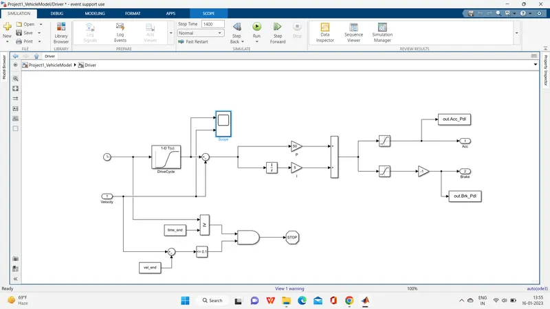
1-Drive model =It is modeled using a ‘Driver’ block, which is a basic PI controller that generates accelerator and brake pedal outputs to match the desired and actual vehicle speeds. In this we use drive cycles fro the based on these results of fuel consumption and emissions the vehicle gets certified and it also forms a basis of uniform asessment. It is based on time, velocity then its all integrate and creates output accelration pedal and brake pedal.
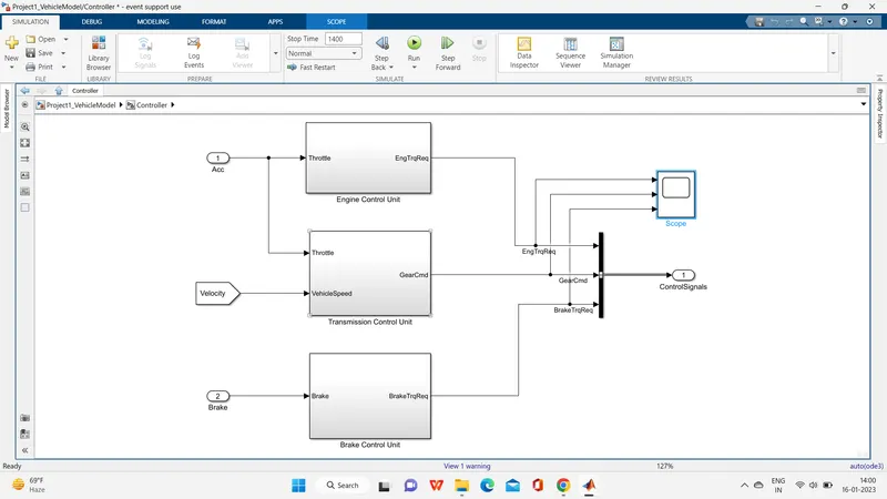
Control Model:-
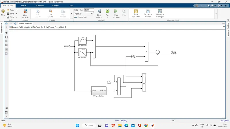
engine converter unit=
In this control model We use engine control unit in that give input Engine speed through creating look up table. in that table we give input Maximum torque and map speed then also create 2nd look up trable in that give input ct torque and map speed then it substracts and multiplied. the engine speed also give to ideal contro speed to integrate from this we meet output of engine required torque.
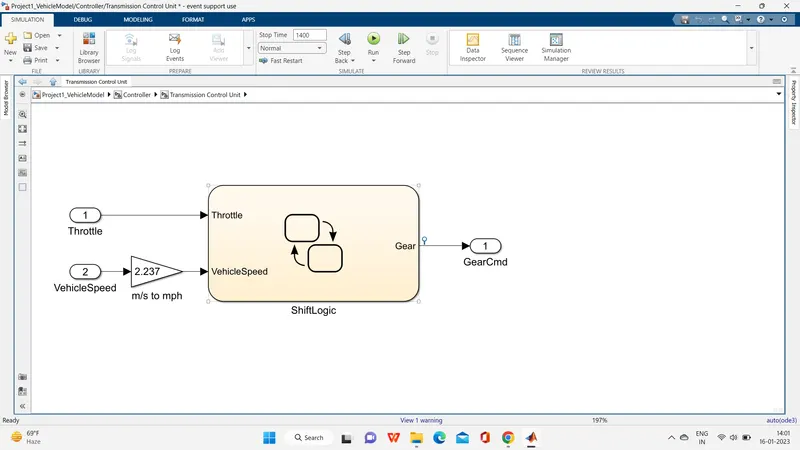
transmission control unit=
In this unit we create steadfy flow variable state for controlling of gears of vehicle as in ascending and descending order with respect to time, speed, distance. and give input to this steady state is vehicle speed in m/s to mph.
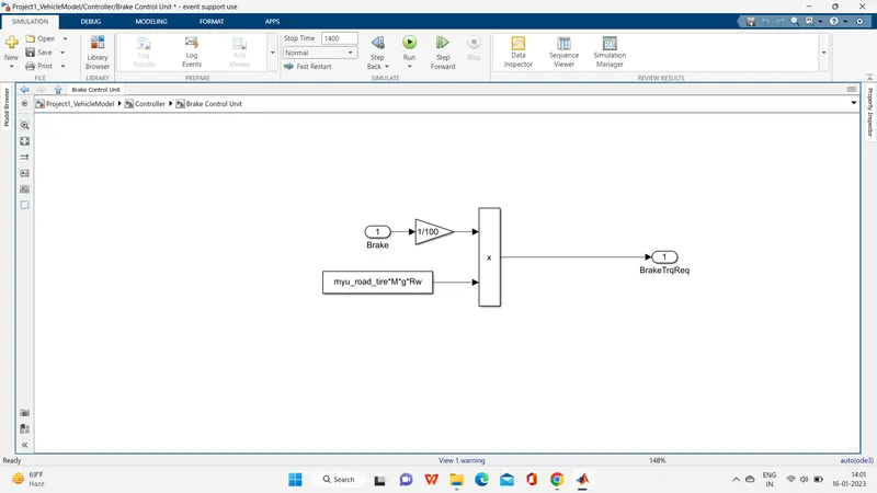
brake control unit=
n this calculate brake torque and then all three control signals output is give to powertrain.
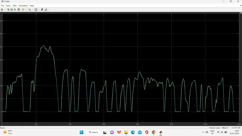
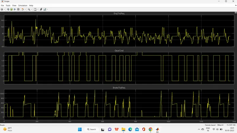
scope=
3] PowerTrain:-
The powertrain encompasses every component that converts the engine's power into movement. This includes the engine, transmission, the driveshaft, differentials, axles; basically anything from the engine through to the rotating wheels.
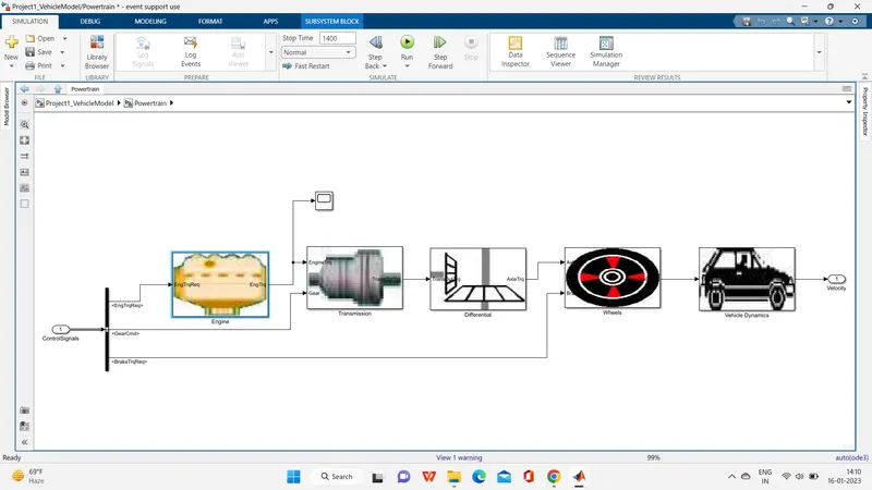
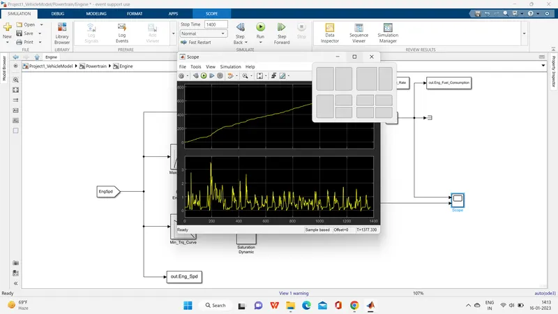
1] Engine:-Engine It converts chemical energy into mechanical energy and produces sufficient power to propel the vehicle forward or backward.
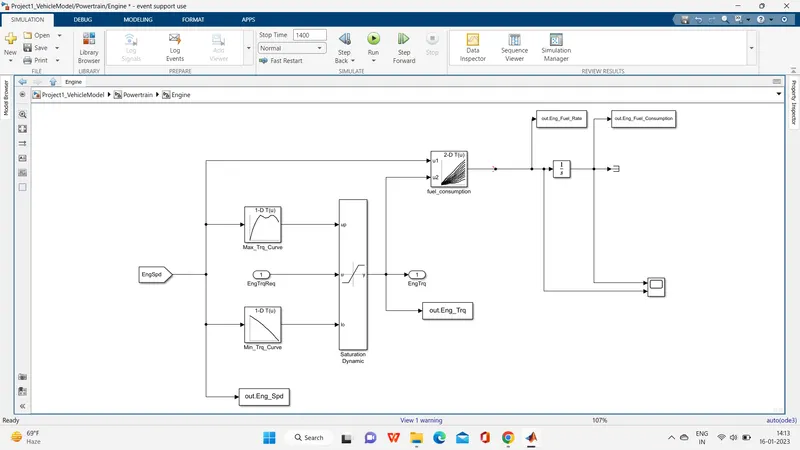
scope=
2] Transmission:-
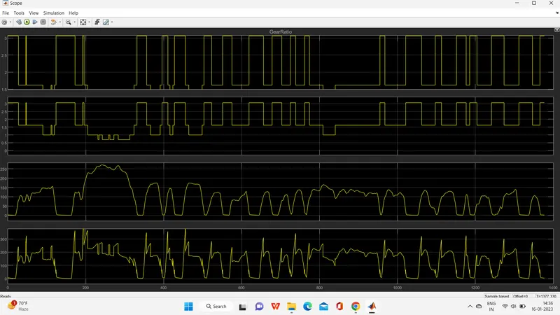
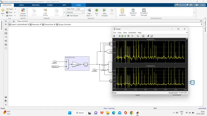
In these model we take engine torque, gear selector from controllerb for transmission of gear ratio. The ratio is multiply by transmission input torque and then the transmission efficiency positive torque and negative torque gives transmission input speed. In this case torque converter connects the engine to transmission it is part of transmission. In it basically engine dynamics and that is decoup
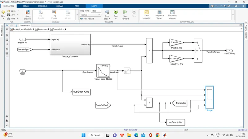
 led.
led.

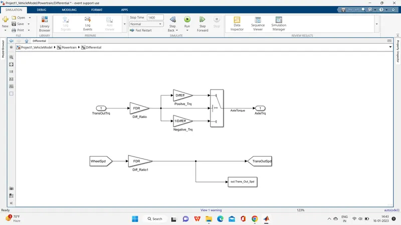
3] Differential:-
In this taking input is the transmission output then its going to the differential ratio multiplied the output and input torque then meet axle torque. The axle torque is a lower than the transmission torque and differential ratio.
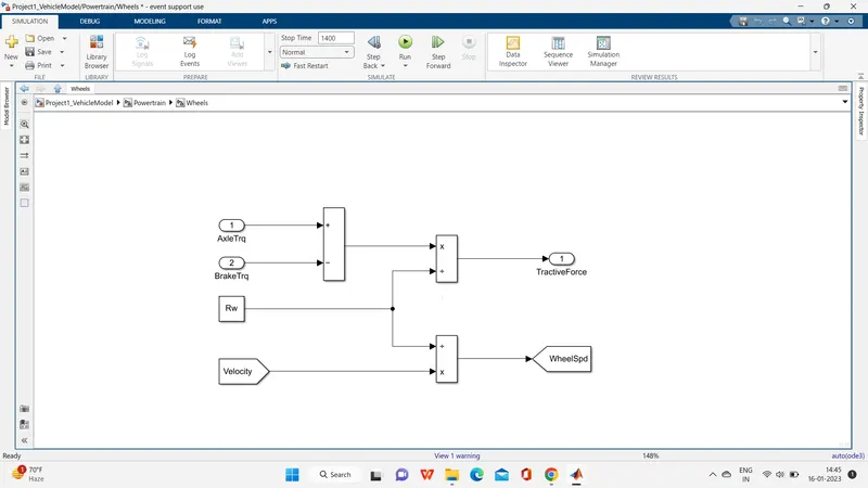
4] Wheels:-
n this model we take the axle torque from differentail and brake torque from controller. it is substracts and multiplied rolling radius and velocity then we meet the tractive force from axle and brake torque. and the wheelspeed is meet using velocity.
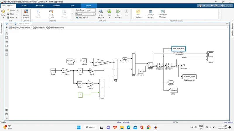
5] Vehicle Dynamics:-
In this takes tractive force and road load. It is dictates vehicle speed based on tractive force and road load.
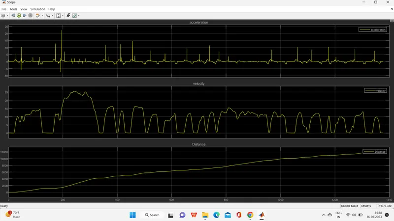
scope=
Now For creating Plots we use MATLAB coding So the coding will give down:-
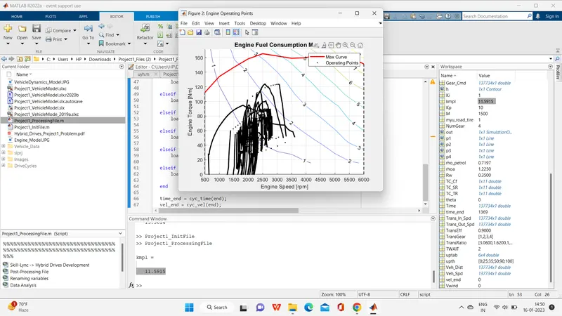
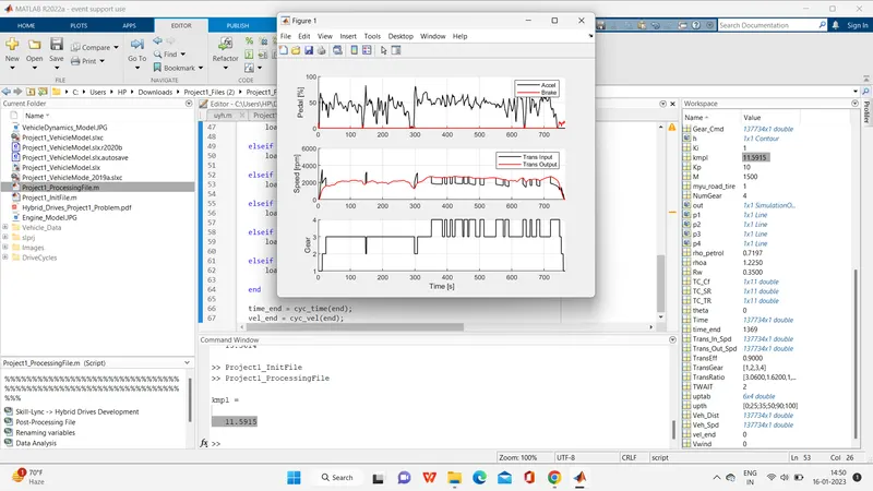
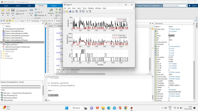
Plotting engine operating points on engine fuel map:-