Project - Analysis of a practical automotive wiring circuit
1.Identify each of the major elements in the above automotive wiring diagram.
The major elements present in the automotive wiring circuit are
- Battery
- Current and Voltage Regulator
- Starter
- Generator
- Distributor
- Ignition coil
- Fuse
- Braker
- Tail switch
- Fuel Gauage
2 Explain the purpose and working of any three elements briefly.
Battery
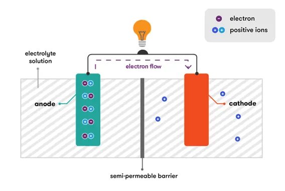
A battery is a device that stores energy and then discharges it by converting chemical energy into electricity. Typical batteries most often produce electricity by chemical means through the use of one or more electrochemical cells. Many different materials can and have been used in batteries, but the common battery types are alkaline, lithium-ion, lithium-polymer, and nickel-metal hydride. Batteries can be connected to each other in a series circuit or a parallel circuit.
Working Principle of Battery
A battery works on the oxidation and reduction reaction of an electrolyte with metals. When two dissimilar metallic substances, called electrode, are placed in a diluted electrolyte, oxidation and reduction reaction take place in the electrodes respectively depending upon the electron affinity of the metal of the electrodes. As a result of the oxidation reaction, one electrode gets negatively charged called cathode and due to the reduction reaction, another electrode gets positively charged called anode.
The cathode forms the negative terminal whereas anode forms the positive terminal of a battery. To understand the basic principle of battery properly, first, we should have some basic concept of electrolytes and electrons affinity. Actually, when two dissimilar metals are immersed in an electrolyte, there will be a potential difference produced between these metals.
Fuse
An Electric Fuse is an Electric device which interrupts the flow of current in an Electric circuit. It is installed in a circuit to stop the flow of excessive current. A Fuse is usually a short piece of wire. The Fuse is made up of a material which has high resistivity and low melting point, so that it melts down due to overheating of the wire during high current flow.
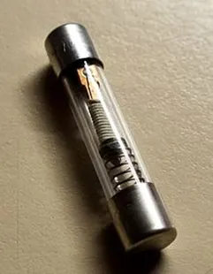
The thickness of the Fuse wire is determined based on the amount of current flow in the circuit. Normally an alloy of tin and lead is used as the Fuse wire, as it has high resistivity and low melting point.
If a fault causes a flow of excess Current then a thin Conductor is used to break the Circuit by melting or separating it, the thin Conductor used is known as an Electric Fuse. A Fuse can be sacrificed if anything in the Circuit goes wrong since they are weak points that are intentionally placed in a Circuit. For example, in order to protect the wiring of the vehicles, a Fuse panel is placed near the batteries of the Car.
The wire inside the Fuse melts if there is an occurrence of high Current due to a short Circuit or an overloaded Circuit. As a result of which the Current stops flowing since the wire has broken.
In orderto stop the flow of Electricity, the Electric Fuse gives up its life. There is a clear plastic window in some Fuses from which one can check if they are still good.
Electric Fuse- Working Principle
The Electric Fuse works on the basis of the heating effect of the Electric Current. It is composed of a non-flammable thin metallic wire with a low melting point.
If a high amount of Electricity is passed from the Electric Fuse, there is a production of heat which causes the Fuse to melt which leads to the opening of the Circuit and the blockage of Current.
Once a Fuse melts, it can be changed or replaced with a new Fuse.
A Fuse is normally made up of elements like zinc, copper, aluminium and silver.
A Fuse acts as a circuit breaker and breaks the circuit in case any fault occurs in the circuit.
It acts as a protector of Electric appliances and also as a safety measure for humans.
3.Starter Motor
A motor starter is an electrical device that is used to start & stop a motor safely. Similar to a relay, the motor starter switches the power ON/OFF & unlike a relay, it also provides a low voltage & overcurrent protection.
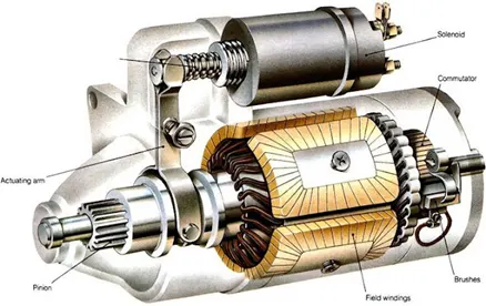
A motor starter is essential for starting an induction motor. It is because of its low rotor impedance. The rotor impedance depends on the slip of the induction motor which is the relative speed between the rotor & stator. The impedance varies inversely with the slip.
The slip of the induction motor is at maximum i.e. 1 at standstill (rest position), thus the impedance is at its minimum & it draws a huge amount of current called inrush current. The high inrush current magnetizes the air gap between the rotor & stator that induces an EMF in the rotor winding. This EMF produces an electrical current in rotor winding that creates a magnetic field to generate torque in the rotor. As the rotor speed increases the slip of the motor decreases & the current drawn by the motor is reduced.
The high inrush current is 5-8 times the normal rated full load current. So such amount of current can damage or burn the windings of the motor that will render the machine useless & it can cause a huge dip in voltage of the supply line that can damage other appliances connected to the same line.
In order to protect the motor from such a huge amount of currents, we use a starter that limits the initial current for a short duration at startup & once the motor attains a certain speed power supply to the motor is resumed. They also provide protection against fault conditions such as low voltage & overcurrent during normal operation.
Working Principle
A starter is a control device that is used for switching the motor either manually or automatically. It is used for safe ON/OFF control of electrical motors by making or breaking its contacts.
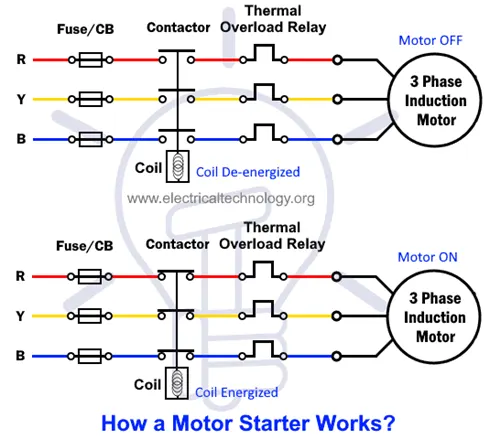
The manual starter is used for smaller motors where the hand operated lever is manually operated (move the contacts position) to the ON or OFF position. The disadvantage of these kinds of starters is that they need to switch ON after power frailer. In other words, they need manual control for each (ON or OFF) operation. Sometimes, this operation may leads to flow high currents in the motor winding which may burn the motor. This is why it is not recommended in most cases where other alternative motor starters with protection are used such as automatic starters.
3.If the total load is 10A from battery, what should be the fuse rating ?
Fuse must be 120% of the rated current , as per the given given load . The Fuse rating for the battery is 12.5 since we don’t have 13 A fuse device . We have to choose closer ratings . As per the fuse standards we can select 15A .
4. If 500W is the load, what is the voltage and capacity of battery you recommend?
Capacity=load*time
load given=500watt
Time =24hours
average of voltage= 12v
Capacity=500*24=12000wh
Amp-hours = Watt-hours / Volts
=12000/12=1000AH
5.Identify any two elements which are connected parallel to each other. Why they are connected in parallel?
To obtain maximum illumination the lamps are connected in parallel. This creates multiple branches or pathways through which current can flow. The resistance in any given branch will determine the voltage drop and current flow through that branch and that branch alone. One of the advantages of a parallel circuit is that the various segments or pathways of the circuit can operate independently of one another. If one element goes open (breaks continuity), it won't disrupt the function of the other. So, with the arrangement an open circuit in any branch causes failure only in that one branch, the other lamps still function normally.
6. Identify any two elements which are connected in series. Why they are connected in series?
Fuses are connected in series to protect electrical circuits from dangerous overloads that could cause them to overheat, melt or catch fire, it stops the flow of current through the circuit. A blown fuse, therefore, is often an indication of an overloaded circuit or a fault such as a short that is causing excessive current flow in the circuit.
The sender in the fuel tank are connected in series so that the varying resistance in the sender will affect the position of the needle on the gauge. It varies its resistance according to the amount of fuel in the tank, and sends a small electrical current to the fuel gauge.