Project
AIM :To study and Carry out a system-level simulation of BAJA all-terrain vehicle using MATLAB and Simulink.
OBJECTIVE :1. To Prepare a technical report explaining the model properties of BAJA ATV model with Continuously Variable Transmission(CVT).and 1.Study the Behavior of BAJA Engine.
2.Study the Behavior of the primary ,Secondary an d Vehicle Velocity by changing the CVT ratio.
INTRODUCTION :
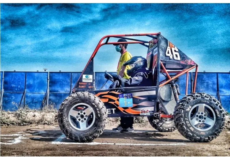
An all-terrain vehicle (ATV), also known as a light utility vehicle (LUV), a quad bike, or simply a quad, as defined by the American National Standards Institute (ANSI); is a vehicle that travels on low-pressure tires, with a seat that is straddled by the operator, along with handlebars for steering control. As the name implies, it is designed to handle a wider variety of terrain than most other vehicles Baja is intended for rough terrain use & for the continuance of an unpleasant landscape. In numerous viewpoints it is like an ATV except this vehicle is tiny in size and contains more secure rollover abilities. The national competition is organized by the SAE India for schools all through the world to structure and create their vehicles and afterward go up against one another. In this competition teams show their engineering skills and make a lightweight and ergonomically fit ATV.The goal in Baja SAE racing is to design, build and race off-road vehicles that can withstand the harshest elements of rough terrain. The vehicles used in Baja SAE racing are often similar in appearance to dune buggies.There are multiple dynamic events, usually four per event, as well as a single four-hour endurance race. The dynamic events include hill climbs, sled pulls, maneuverability events,rock crawls, and suspension & traction events.
CVT :
A CVT is a type of automatic transmission that delivers seamless acceleration without interruption for gear shifts. Instead of fixed gears, it uses a pair of variable-width pulleys that are connected by a flexible belt.
The Main Parts of CVT are Primary Pulley ,Secondary Pulley and Belt,
At low speed:
In Continuously Variable Transmission system, belt pushes the pulleys and as soon as the crankshaft rotates the primary or driving pulley’s movable sheave moves away from the static sheave which makes the smaller diameter of the driving pulley. Due to the same movement of sheaves at the same time secondary or driven pulley becomes larger in diameter which leads to creating greater torque at the vehicle’s starting position.
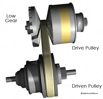
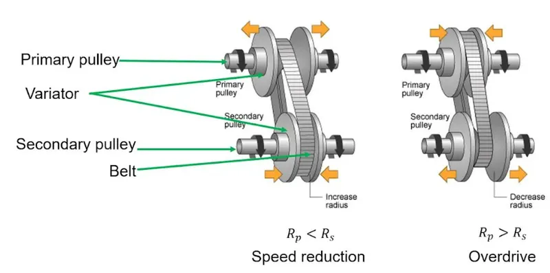
Fig:
At high speed or High Gear:
While accelerating, vehicle required high speed (Doesn’t required torque) for that driven pulley or secondary pulley diameter become smaller (smaller diameter more revolutions) as the moveable sheave moves away from the static sheave. Due to the same movement of sheaves at the same time, primary or driving pulley becomes bigger in diameter which creates gear ratio between them.
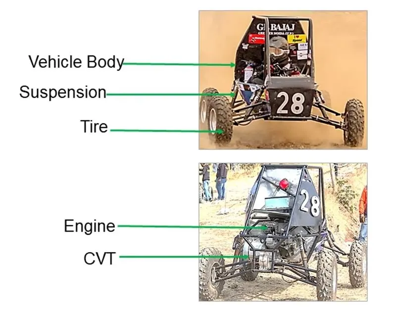
COMPONETS OF ATV:
MAJOR COMPONENTS USED IN THIS SIMULATION
1.VEHICLE BODY :
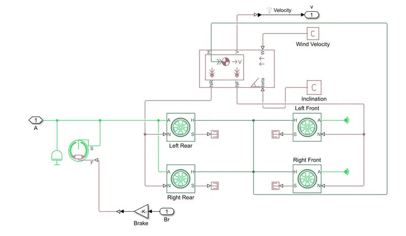
a two-axle vehicle body with longitudinal dynamics and motion. The body accounts for adjustable mass, aerodynamic drag, road incline, and weight distribution between axles due to acceleration and road profile. The vehicle can have the same or a different number of wheels on each axle.The Vehicle can also have a center of gravity(CG) that ia at or below the plane of travel.
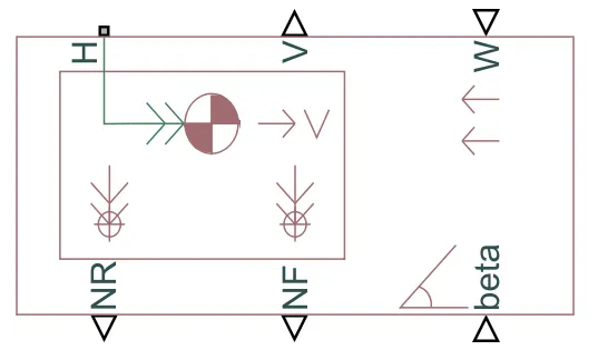
PORTS;
- H :Horizontal motion
- V :Vehicle velocity (m/s)
- W :Headwind speed (m/s)
- NR :Rear Axle normal force (N)
- NF :Front Axle normal force (N)
- beta :Road inclination Angle (rad).
2.GENERIC ENGINE :
The Generic engine block Represents a system-level model of spark-ignition and diesel engines suitable for use at initial stages of modeling when only the basic parameters are available i.e Speed torque and Speed power parameters provided by the designer.
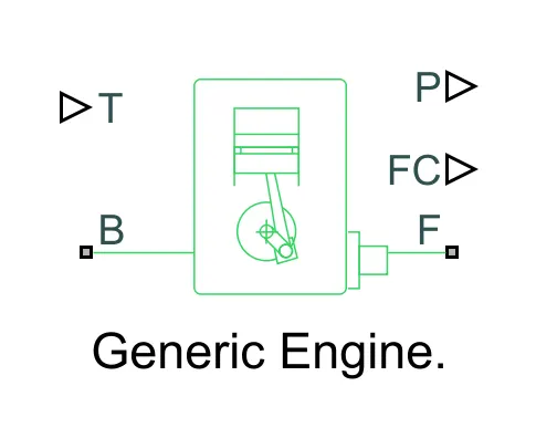
Where,
T-Physical signal input port specilizing the normalised engine throttle level
B-Rotational conserving ports representing the engine block
P-physical signal output ports reporting the instaneous engine power,in W
FC-physical signal output ports reporting the fuel consumption rate in kg/sec
F-Rotational conserving ports representing the engine crankshaft.
3.CVT
The variable gear arrangement of CVT in this model is repesented by the variable ratio Gear box.
Represents a variable ratio gearbox such as implemented by mechanical belt CVT, electric, or hydraulic transmissions
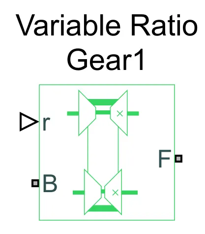
Ports;
r-variable transmission ratio(input)
B-Base Pulley
F-Follower Pulley or driven pulley
4.Simple Gear
The simple gear is a combination of a driver and driven gear where the speed is reduced by the gear ratio, it is defined as the ratio of Follower Gear Speed to the Base Gear speed.
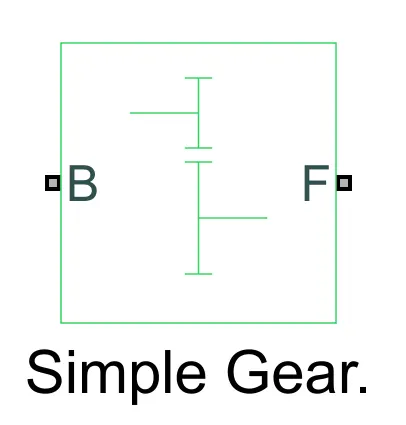
Ports;
B-Base Gear or Driver Gear
F-Follower Gear or Driven Gear
5.Tire
The Vehicle body is connected to the 4 tires each per Axle to move the Vehicle according to the power in put to the axle.
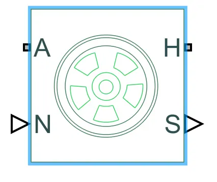
Ports;
A-Axle
H-mechanical translational conserving port for the wheel hub through which the thrust developed by the tire is applied to the vehicle.
N-Normal Force
S-Tire Slip
6.Brake
Represents a brake arranged as two pivoted rigid shoes symmetrically installed inside or outside a drum and operated by one actuator. The actuator force causes the shoes to exert a friction torque on a shaft connected to the drum.
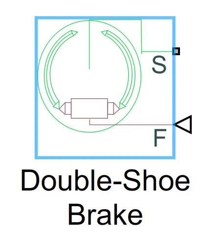
Ports;
S-conserving rotational terminal associated with the drum shaft
F-physical signal port representing the force input to the actuator.
TYPES OF MODEL
- BAJA ATV Model Without Dashboard
- BAJA ATV Model With Dashboard
- BAJA ATV Model With Lookup Table Data Extraction
- BAJA ATV Model With Mapped Lookup Table Without Dashboard
- BAJA ATV Model With Mapped Lookup Table With Dashboard
BAJA ATV Model Without Dashboard
Main Model
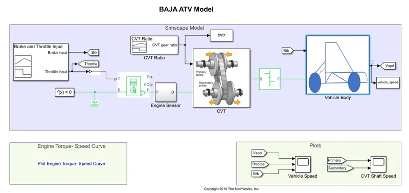
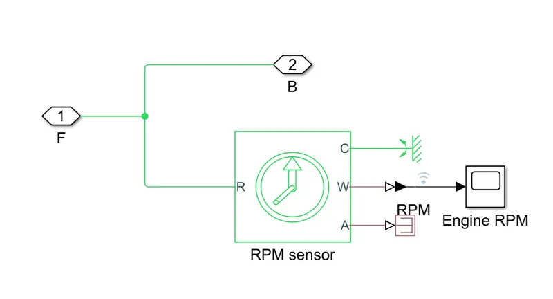
ENGINE SENSOR
CVT SYSTEM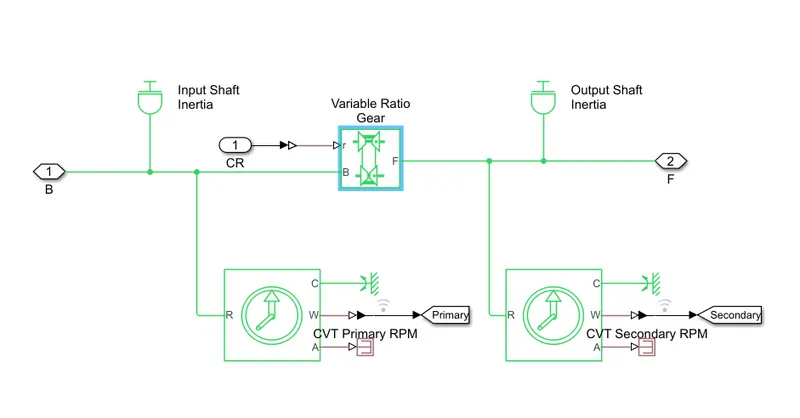
VEHICLE BODY MODEL
FLOW PROCESS
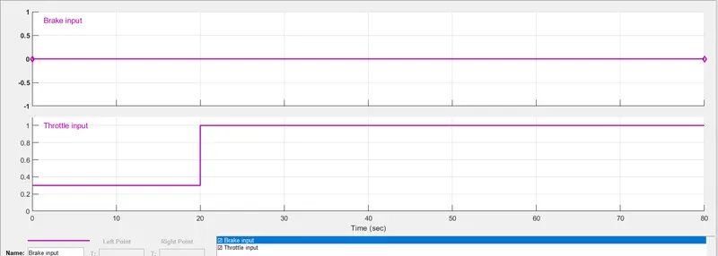
The Throttle signal and Brake signal is Generated by signal builder block and the signal is given input to Generic Engine.
Input as Brake =0 and the Throttle =0.3 for 20 sec and throttle is increased to 1 after 20 sec for remaining time period.
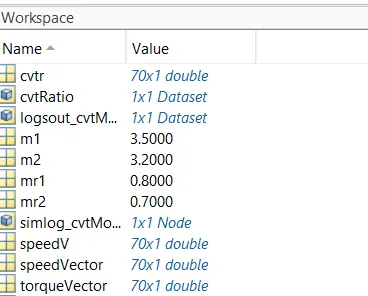
The Torque and Speed vector are Extracted for the Given Speed and Torque Plot in the Matlab Workspace.
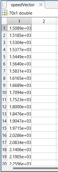
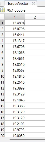
The engine will generate the output rpm which can be taken from the crank shaft output .this speed is given to ideal rotational motion sensor to sense the output rpm.
The same output speed will be given to a simple gear machanism to reduce the speed where the Gear ratio is "4".
The CVT ratio is provided to the variable Ratio Transmission block through signal bulider.
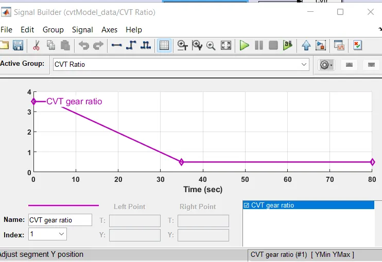
The power from CVT is input to the axle and vehicle acceleration according to speed.
The velocity is taken as a output from the vehicle body for futher analysis.
RESULTS
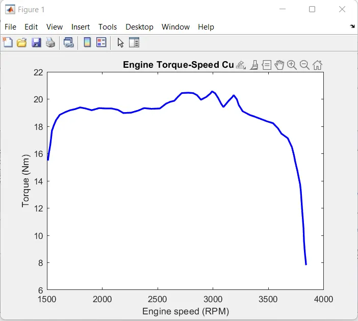
The Speed and Torque are given input from the MATLAB workspace window to generate the output rpm accordingly.
ENGINE SPEED PLOT
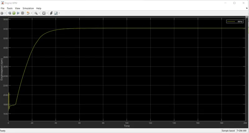
When we are giving the throttle the velocity is increasing after some time it is reaching the Maximum velocity. Maximum rpm is reached is 3400 rpm.
VEHICLE SPEED VARIATION WITH THROTTLE AND BRAKE INPUT
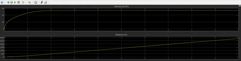
From the graph we can see that vechicle attains maximum speed of 12km/hr at throttle =0.3 and for 20sec .after 20 sec the vechicle gradually attains the maximum speed of 55 kmph where it remains constant throught the cycle.
CVT primary and Secondary Speed
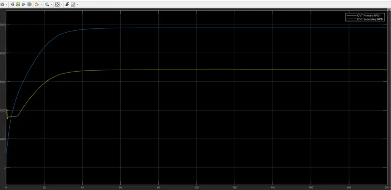
The primary and secondary Rpm ,vehicle velocity by changing the CVT ratio.
When the CVT Ratio is less then 1 the rpm of Primary is greater than the secondary rpm .
here the CVT ratio is greater than 1 the secondary rpm is greater then the primary rpm.and the Engine Rpm is same as the secondary rpm.
2.BAJA ATV Model With Dashboard
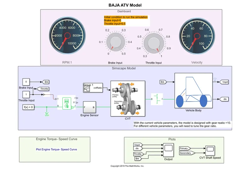
The Model Workflow is Same as the process of BAJA ATV Model Without Dashboard but the Throttle and brake inputs are controlled by Knob.Knob is provided to control both the inputs in real time for user. one can vary and analise the vehicle speed for different throttle input and when the brake is applied.
RESULTS:
Vehicle speed Variation with Throttle and Brake inputs
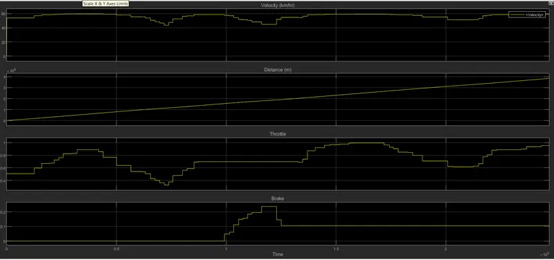
From the Graph we can see that the initial throttle has a base rate of 0.5 and speed is increasing .when we are giving the throttle from the knob the velocity is increasing in stair case manner and brake was applied at different point of time at different throttle values.Increasing the throttle input increases the speed over time and settles at 53.8 km/hr.but after the instance where the brake is applied there is decrease in the vehicle velocity.the brake value was 0.3 was the highest so the graph justify the vehicle behavior.
CVT primary and secondary speed
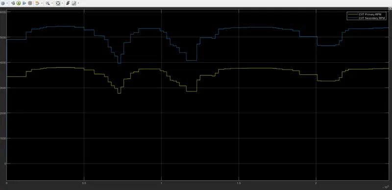
here we have both the CVT primary and secondary RPM the intial increase and settlement were for throtle value 0.5 when there is no brake applied .after that the behavior in the result of variation in both the input the down steps are when the brake is applied and the upsteps are the result of realising the brake.
CLOSED LOOP
3.BAJA ATV Model With Mapped Lookup Table With Dashboard
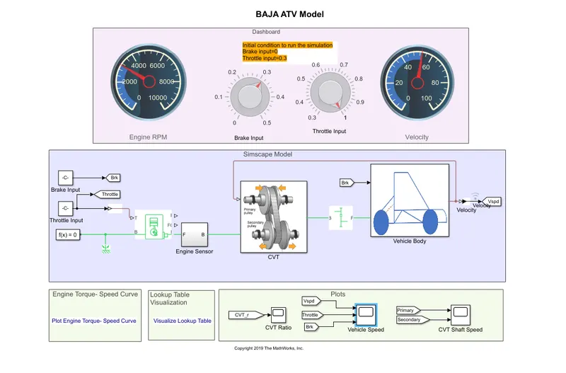
The Model Workflow is is given by the CVT gear ratio is given using the Lookup table .in this model the lookup data is the realtion between CVT ratio and Vehicle speed which is incroporated using a simple MATLAB script. in study 1 a cvt gear ratio had to be input using the signal builder to see the effect on the vehicle velocity. however it is not feasible in reality and does not give the real time analisis.Through this lookup table the CVT can be modeled based on the vehicle speed as feedback is taken from the vehicle to calculate gear ratio.
RESULTS:
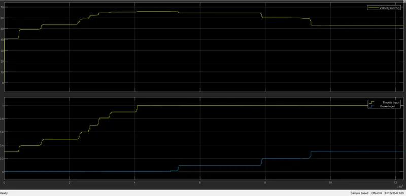
CVT RATIO VS VEHICLE SPEED FOR THROTTLE AND BRAKE
CONCLUSION :
A technical report explaining the model properties of BAJA ATV model with Continuously Variable Transmission(CVT) is modeled using two main study.and
1. Behavior of BAJA Engine is Studied using the Speed and Torque input.
2. Behavior of the primary ,Secondary and Vehicle Velocity by changing the CVT ratio is studied for different model.
REFERENCES: