Project
ROSHAN ARYAL EV BATCH 17
Aim: To carry out the system level simulation of Baja All terrain Vehicle.
Introduction:
Baja SAE is an Collegiate Design competition which is run by the society of Automotive engineers International where the students from all over the universities participate and designed a small off road car. All terrain vehicle (ATV) which is also famous as a quad bike, is a vehicle which generally travels with low tire pressure with a seat and handle for operator for controlling it. In this project, the system level configuration for the Baja All terrain vehicle had had been made in simulink environment and simulated to analyze the performance of the various component.
Model Development
All terrain vehicle has been modeled in simulink environment by using the simscape and simulink block arrangement as shown in figure 1. For modelling the engine, a generic engine block is used, where the throttle input from 0.3- 1 was provided by the help knob from the dashboard. The one end of the generic engine was connected to rotational mechanical reference and the other end was connected to the rest of the system. The speed and torque vector for the generic engine block is defined from the base workspace. The inital velocity and engine inertia was considered as 1750 rpm and 0.008 kgm2. The throttle input was connected to the 'T' port of the generic engine , while the mechanical rotational reference was connected to the 'B' port and further system was connected to the 'F' port of the generic engine.
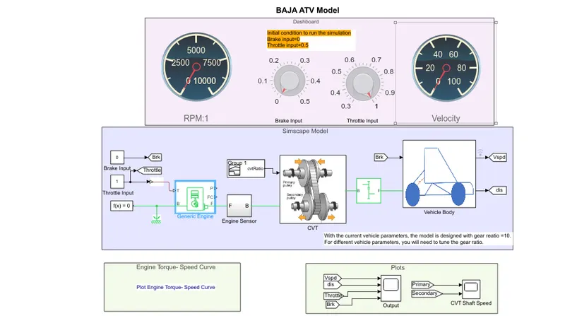
Figure 1: Simulink Model for Baja ATV Vehicle
To know a engine rotational speed, a engine sensor subsystem model was developed which consists of a ideal rotational sensor for measuring the speed of the engine. The connection for the different port is shown in figure 2.
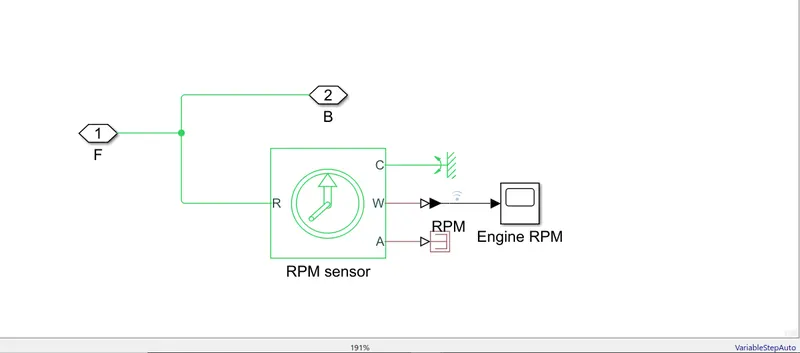
Figure2: Block arrangement for engine sensor subsystem.
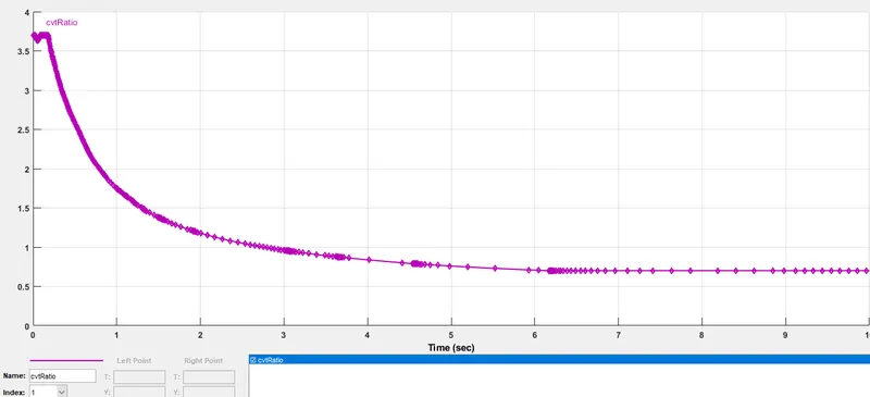
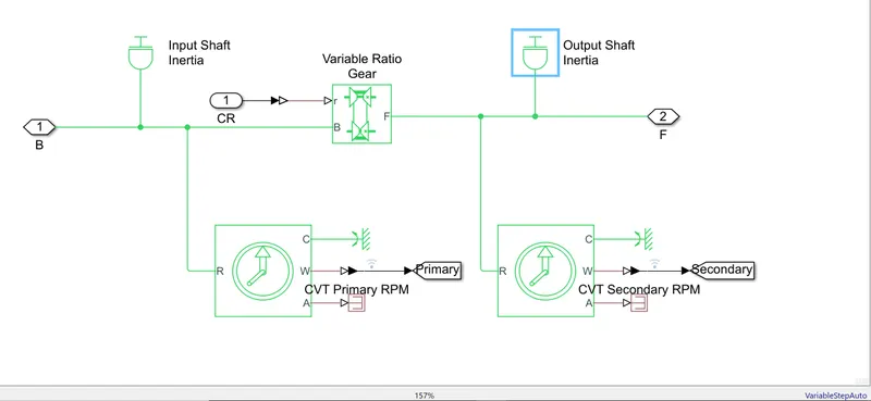
The power and torque from the engine was transferred to the rear axle of the ATV model via CVT (Transmissin system) and simple gear arrangement. The CVT (transmission model) was modelled by using variable ratio transmission where the gear ratio for the block was provided by use of signal builder with the highest gear ratio of 4 as shown in figure 3a. To make the model more realistic an inertia was added at primary and secondary shaft of the transmission system. To observe the speed variation between the primary and secondary shaft two ideal rotational sensor was used as shown in the figure 3b.
a b
Figure 3 : a) Gear ratio value for the variable ratio transmission block b) CVT model made of from the simscape block.
After the transmission system block a simple gear block was used with a gear ratio of 10 and then it is send to the vehicle body. In the vehicle body, the torque and power from the simple gear block was connected to the rear axle of the vehicle body. Brake input which was by the knob with a range of 0-0.5 was connected double shoe brake which was capable of providing the braking force from 0-500 N and this double shoe brake was also connected to the rear axle of the vehicle. An inertial load was also connected before the connection of the rear axle of the vehicle for making the model more relasitc. A rear wheel drive vehicle was modelled as the power was given to the rear axle and front axle was rotating as a free. The tires were modelled by using the magic formula tire block from simscape library with a radius of 0.3m. The 4 tires were connected to the vehicle body as shown in the figure 4. The inclination and wind velocity for the model was not considered and taken as 0. The mass of the vehicle was taken as 250 Kg, a pair of wheel for the axle was considered by keeping other parameters constant while modelling the vehicle body. The velocity output was given from the vehicle body which was integrated over time period for getting the total distance travelled by vehicle.
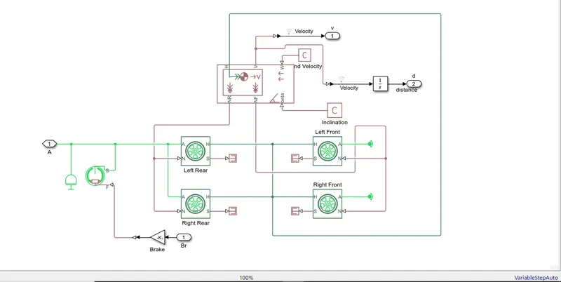
Figure 4: Block arrangement for Vehicle Model
Output:
The model was simulated for 1000 seconds and the characteristics like velocity distance travel , primary and secondary speed of a CVT and accleration and brake pedal position was stuidied. When full throttle was applied to the model than the vehicle was able to reach the top speed of 60 km/hr around 10 seconds and was able to travel the distance of 15 km. Figure 5a shows the characteristics of vehicle when full throttle was given.
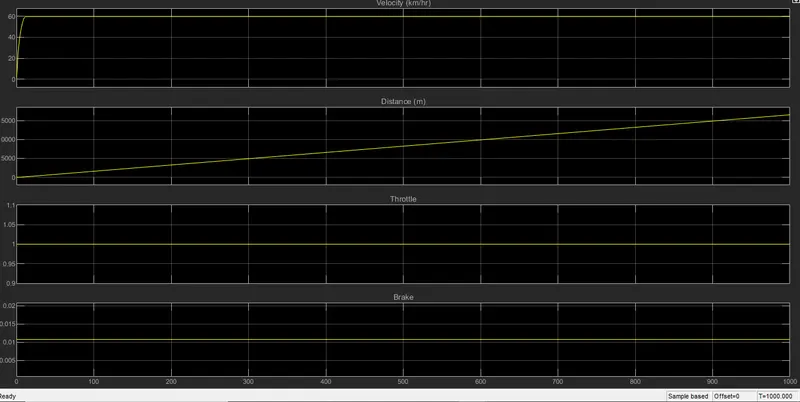
Figure 5a : Vehicle characteristics when full throttle was applied.
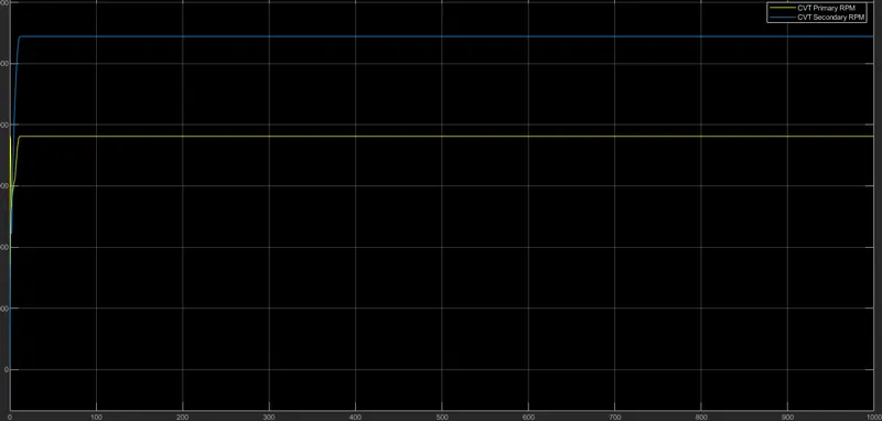
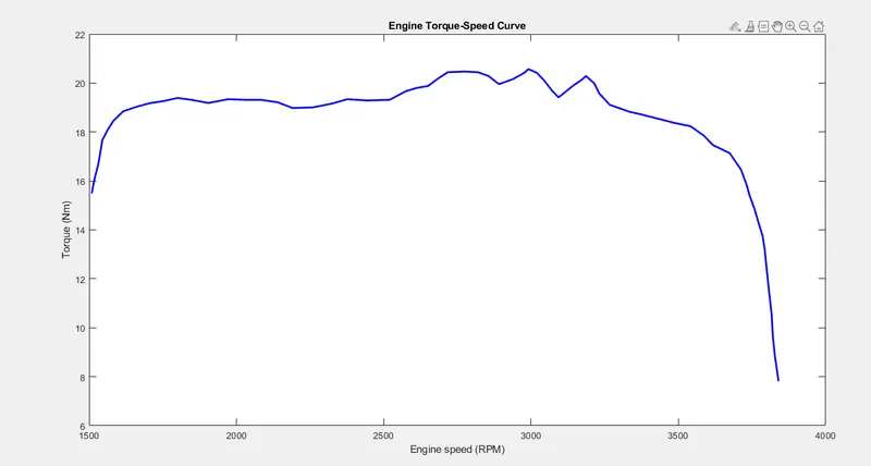
In second plot we can observe in difference in the speed of primary and secondary wheel of an CVT drive. we can observe that, speed of secondary was around 5500 rpm when the speed of the primary gear was near 4000 rpm as shown in the figure 5b. Figure 5c shows the speed vs torque charaacteristics of an engine. Here we can observe the maximum torque was obtain for limited range of engine speed and was around 20 Nm. The speed range for the maximum torque was around 2500 rpm to 3200 rpm.
b c
Figure 5 b) Speed of primary and Secondary gear of an CVT c) Torque speed characteristics of an Engine
Conclusion:
The system level simulation for the model is done and detailed report has been drafted.