Project
Aim: To perform system-level simulations and to prepare technical report on various models of Baja all-terrain vehicle with Continuously Variable Transmission.
Theory: An all-terrain vehicle (ATV) is a motorised off-highway vehicle with a seat designed to be straddled by the operator and handlebars for steering control that travels on low-pressure or non-pneumatic tyres. An all-terrain vehicle (ATV), alternatively called as a light utility vehicle (LUV), a quad bike, or simply a quad. The figure (1) showing different types of ATVs from various manufactures.
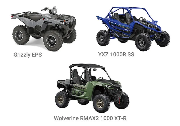
Figure (1) All-Terrain Vehicles
This report is focusing on a Baja model of all-terrain vehicle with Continuously Variable Transmission. The Society of Automotive Engineers International hosts a Collegiate Design Series competition called Baja SAE (SAE International). Small off-road cars are designed and built by teams of students from universities all over the world.
A continuously variable transmission (CVT) is an automatic transmission that can smoothly shift gear ratios throughout a wide range. Other transmissions, on the other hand, only offer a limited number of fixed-step gear ratios. With proper control, a CVT may be able to keep the engine running at a steady RPM while the vehicle is moving at different speeds.
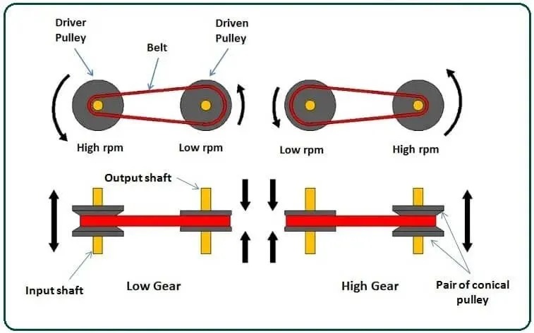
Figure (2) Working of continuously variable transmission
A V-belt travels between two variable-diameter pulleys in the most popular form of CVT. The pulleys are made up of two cone-shaped parts that travel back and forth. The V-belt runs between these two sections; hence the pulley's effective diameter is determined by the distance between the two halves. Since the belt's V-shaped cross-section allows it to ride higher on one pulley and lower on the other, the gear ratio is modified by bringing the two sheaves of one pulley closer together and pushing the two sheaves of the other pulley farther apart.
Simulink Blocks: The major blocks of the vehicle used are Generic Engine, CVT, Simple Gear, Vehicle Body and Tyre, it’s details and usage in the models are described.
Generic Engine: The Generic Engine block is a generic internal combustion engine that can be used for both spark-ignition and diesel engines. Parameterizations for speed-power and speed-torque are available. The normalised engine torque is specified via a throttle physical signal input. The engine block and ports details are given in below figure (3).
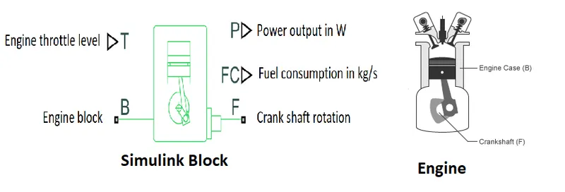
Figure (3) Generic Engine Block
CVT: A continuously variable transmission (CVT) is an automatic transmission that can shift between gear ratios in a seamless manner and more about working principle explained above section.
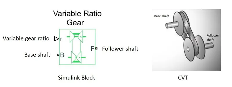
Figure (4) Variable Ratio Transmission Block
The Variable Ratio Transmission block depicts a gearbox that dynamically distributes motion and torque between the base and follower axes of two connected driveshafts.
Simple Gear: The Simple Gear block indicates a gearbox that forces the coupled driveline axes of the base gear, B, and the follower gear, F, to corotate with a defined ratio. The ratio predefined as 10 in this particular model.
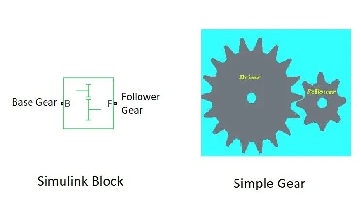
Figure (5) Simple Gear Block
Motion is given to base gear and follower rotates with respective of gear ratio provided.
Vehicle body: The block represents vehicle body with two axles, Body mass, aerodynamic drag, road gradient, and weight distribution between axles due to acceleration and road profile are taken into account by this block. On each axle, the vehicle can have the same number of wheels or a different number. The car does not travel vertically. The port details are included in below figure (6).
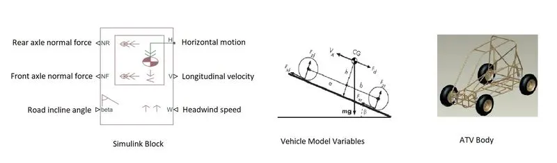
Figure (6) Vehicle Body Block
Tyre: Tire (magical formulae) block is used to indicate functions of wheel. In this project the ATV has 4 wheels and 4 tyre blocks are used in each model. The ports of tyre are explained in the diagram. user can define parameters like tyre compliance, inertia, and rolling resistance to improve the fidelity of the tyre model.
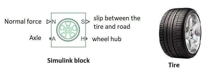
Figure (7) Tire Block
Simulink Models: Different models of all-terrain vehicle for simulations and its explanations are given below.
BAJA ATV MODEL WITHOUT DASHBOARD
1.Simulink Model:The model of Baja ATV without dashboard is shown in figure (8) and its detailed explanation of working, inputs and outputs are given.
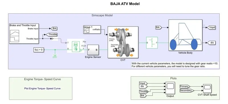
Figure (8) Baja ATV model without dashboard
The model contains several subsystems and blocks its logic and descriptions are listed in this section.
Brake and throttle input: Signal builder block define the brake, throttle value to the generic engine. The brake input is zero and throttle value given as 0.5, these are constant throughout the time duration. The brake input connected to brake shoe and output scope with help of Goto block.
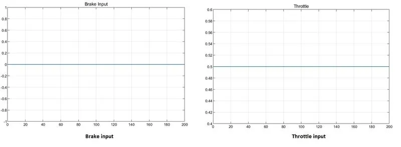
Figure (9) Brake and Throttle Inputs
Generic Engine and Engine sensor: It act as the engine of this vehicle, throttle value given as input to T port. The rotation of the crankshaft will vary according to the throttle. Engine sensor subsystem is to record rpm of crankshaft, it is plotted using scope and ideal rotational motion sensor will sense the rotation of crankshaft.
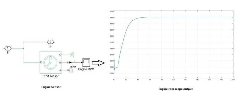
Figure (10) Engine Sensor and RPM graph
It is clear from the figure that the rpm of crankshaft deviated initially and gradually increased to reach above 3400 rpm within 60 seconds.
Continuously variable transmission (CVT): The crankshaft rotation and CVT ratio using signal builder are given inputs to the CVT named subsystem. The input graph of CVT ratio is given below.
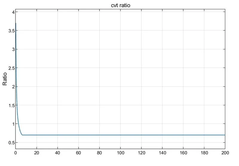
Figure (11) CVT ratio Graph
The two-inertia blocks representing driver and driven pulley shafts which are connected to variable ratio gear. The Variable Ratio Transmission block depicts a gearbox that dynamically distributes motion and torque between the base and follower axes of two connected driveshafts. The ideal mechanical rotational motion sensors identify the rpm of primary and secondary shafts. The entire subsystem act as typical CVT. The rotation from the follower gear shaft is connected to next block, which is simple gear.
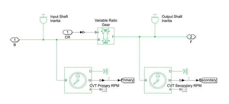
Figure (12) CVT Subsystem
The rpm of primary and secondary shafts is diverted to a scope named CVT shaft speed and the graph is given below.
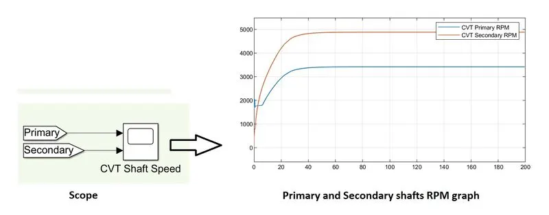
Figure (13) CVT Shaft Speed Graph
It is evident that the primary pulley rpm initially varies and both shaft reaches peak values almost at same time.
Simple Gear: This block act as the gear box of the AVT vehicle Follower (F) to base (B) teeth ratio given as 10. The follower gear rotation is further connected to tyres.
Vehicle Body: The body part of vehicle is defined in this subsystem. The subsystem blocks and connections are shown in figure (). Vehicle body subsystem mainly contains tyre, brake and body. The brake input and gear are connected to the vehicle body subsystem.
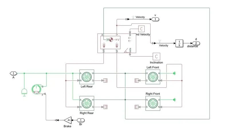
Figure (14) Vehicle Body Subsystem
There are four wheels to this model and it is implemented with four tyre blocks. A common point of normal force port N from the Rear tyres connected to NR port of vehicle body block, similarly N ports from the front tyres are connected to NF port of body. Horizontal motion H port of body also connected to H ports of tyres.
The Double shoe brake block is used to perform braking operations, the input the actuator force port F is given. S port is connected to the drum shaft.
Overall,The acceleration and brake provided by signal builder to the Engine, which is connected to continuously variable transmission. The drive force for the system is produced by the engine and transferred to CVT. Secondary shaft of CVT is connected to gear, Where the motion is distributed to Vehicle body. Vehicle body mainly contains four wheels and brake. The speed and distance are measured from the body of vehicle.
Plots: The plots obtained from the model is listed below.
1.Velocity vs Time
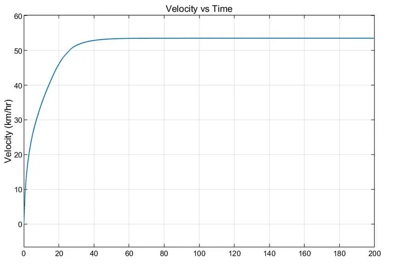
Figure (15) Velocity Graph
The velocity of vehicle rapidly increased in the 40 seconds and reaches maximum velocity about 60 km/hr. After 40 seconds the velocity value remains steady.
2.Distance vs Time
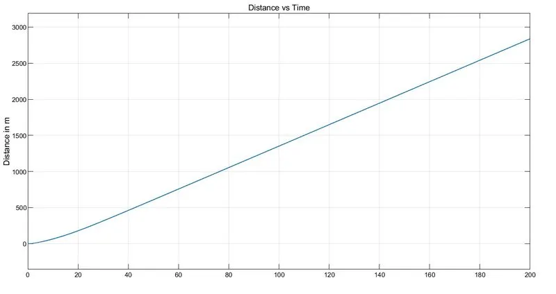
Figure (16) Distance Graph
The distance is increasing linearly because of constant input throttle.
3.Engine speed and torque curve
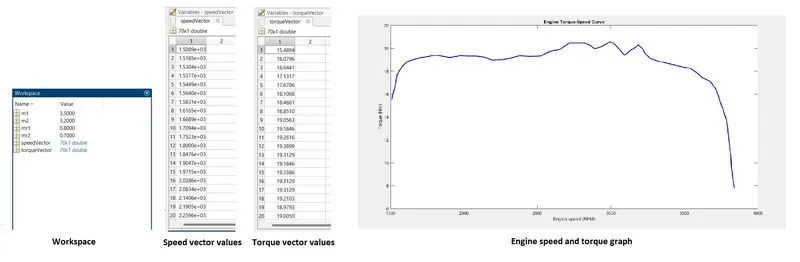
Figure (17) Workspace and graph of Speed and Torque
The values of speed and torque vectors are predefined in the MATLAB workspace and its graph is shown above. The maximum speed is 3840 rpm.
BAJA ATV MODEL WITH DASHBOARD
2.Simulink Model: The Baja all-terrain vehicle with dashboard model is given in the figure (18). All the parameters are same except the inputs. The inputs could be adjusted by the user to improve simulation more realistically. The throttle and brake inputs are given using respective knobs.
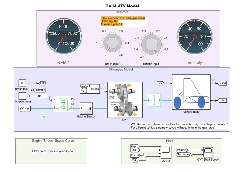
Figure (18) Baja ATV model without dashboard
Plots:
1.Throttle Input
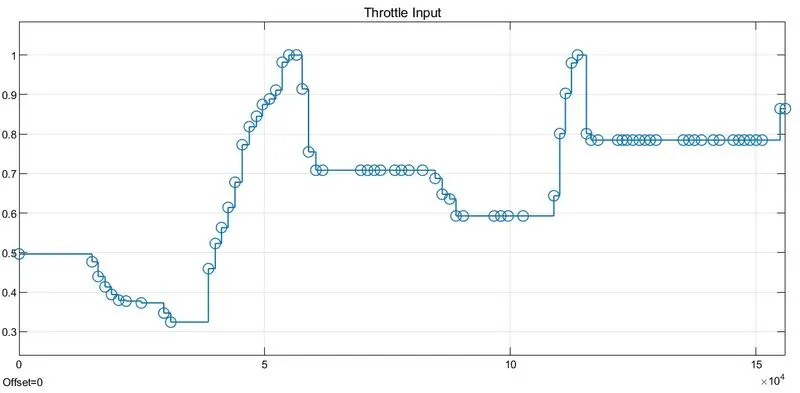
Figure (19) Throttle input given through knobs
Initially 0.5 and vary continuously to match with real conditions. The maximum throttle is 1.
2.Brake Input
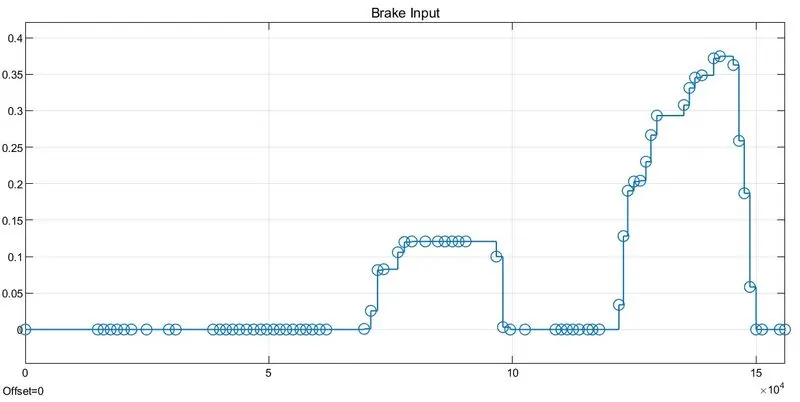
Figure (20) Brake input given through knobs
Initially 0 and vary some times to match with real conditions. The maximum value of brake input is 0.5.
3.Velocity vs Time
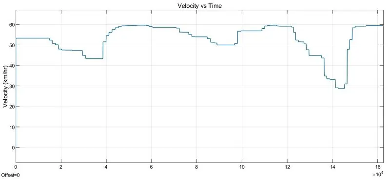
Figure (21) Velocity Graph
The velocity of vehicle responds to throttle and brake inputs. Maximum speed is near to 60 kmph at throttle near to 0.8 and decreases when applying brake. When the throttle is maximum the speed also reaches it’s peak.
4.Distance vs Time
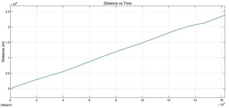
Figure (22) Distance Graph
The displacement is not showing severe changes. When the speed reduces distance is varying slightly downwards.
5.CVT Shaft Speed
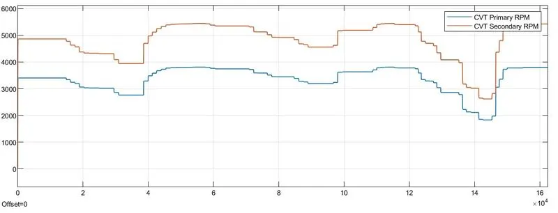
Figure (23) CVT shaft speed Graph
The shaft rpm of primary and secondary of CVT are changing similarly. The velocity of the vehicle is showing exact behaviour of this graph.
BAJA ATV MAPPED MODEL WITHOUT DASHBOARD
3.Simulink Model: This model has some difference with previous models whereas, the major one is method of CVT ratios feed into the CVT subsystem. The model diagram is shown in figure (24).
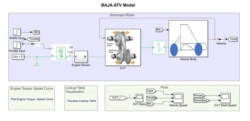
Figure (24) Baja ATV model mapped without dashboard
Brake and Throttle Inputs: The inputs are with help of step block. The brake input remained zero throughout the end while, throttle input started at 0.3 and stepped to 1 in 20 seconds.
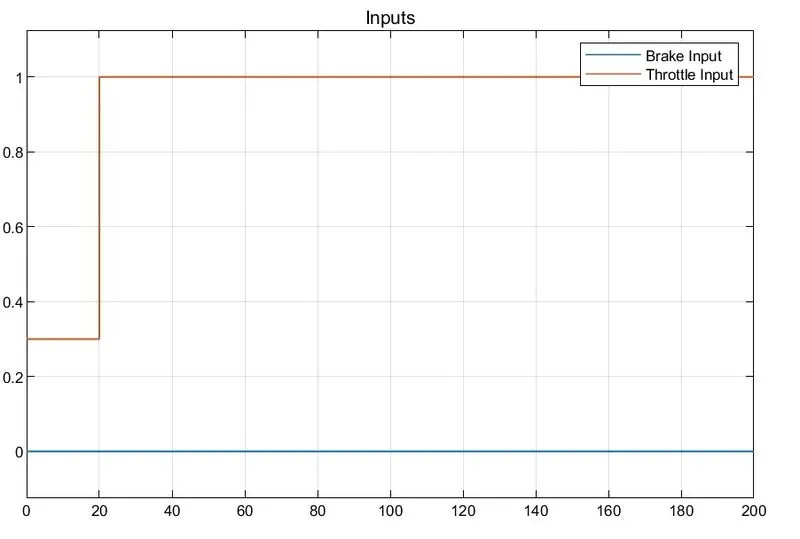
Figure (25) Throttle and Brake Inputs
CVT: The ratio is connected with velocity of the vehicle and Lookup Table is used to define current CVT ratios. The previous velocity will depend on the current CVT ratio.
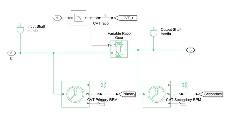
Figure (26) CVT Subsystem with Lookup Table
The following graph showing CVT ratio vs time. At starting it was 3.5 and fallen to 0.5 within 40 seconds.
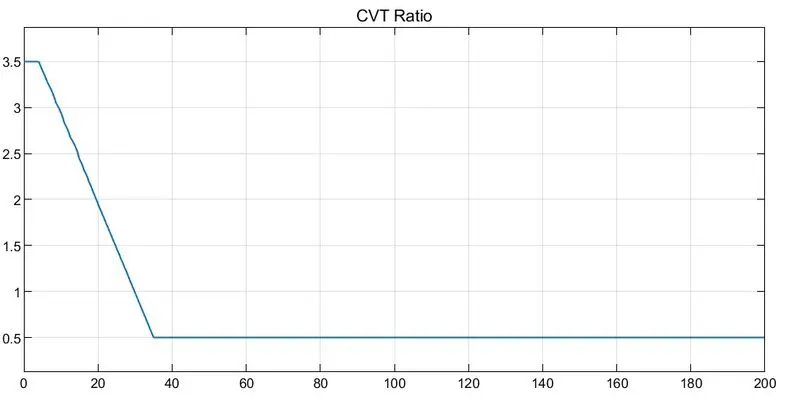
Figure (27) CVT Ratio
Plots:
1.Velocity vs Time
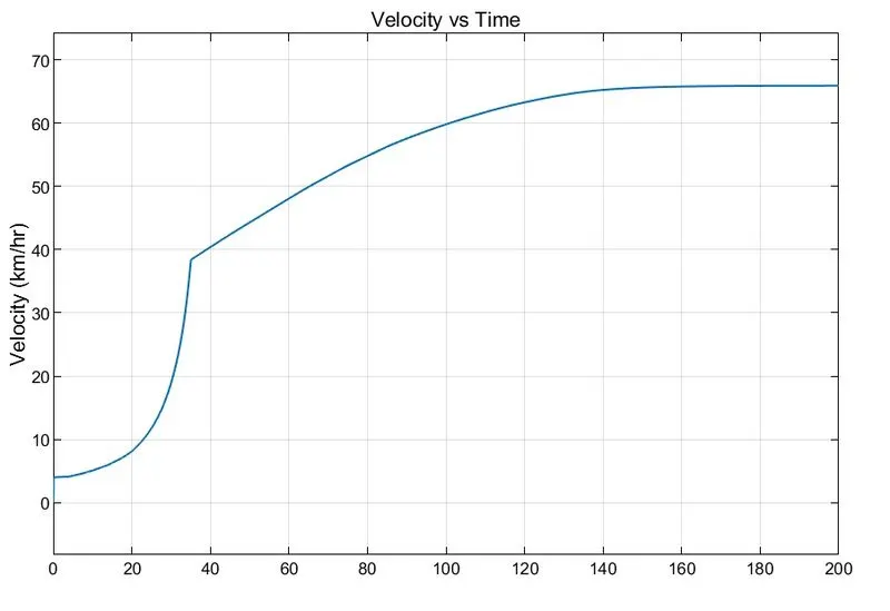
Figure (28) Velocity Graph
The velocity was slowly increased in 20 seconds. Within 20-40 seconds there is a rapid hike in velocity this is due to the throttle applied. Only after 140 seconds the vehicle reaches its highest speed around 65 kmph.
2.CVT shaft Speed
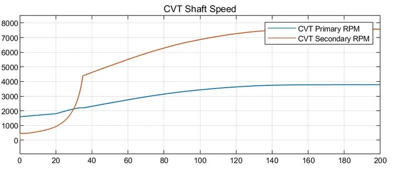
Figure (29) CVT Shaft Speed
The secondary shaft showing same behaviour of velocity hence it is directly connected. The primary shaft rpm is mildly increased.
3.Lookup Table
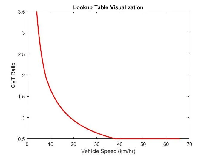
Figure (30) Lookup Table Visualization
In the lookup table block parameters are predefined. The lookup table visualisation graph shown in figure (30) and from the figure cvt ratio and velocity relation can be identified.
BAJA ATV MAPPED MODEL WITH DASHBOARD
4.Simulink Model: In this model there is a dashboard, where throttle and brake inputs can be adjusted by user with the respective knobs.
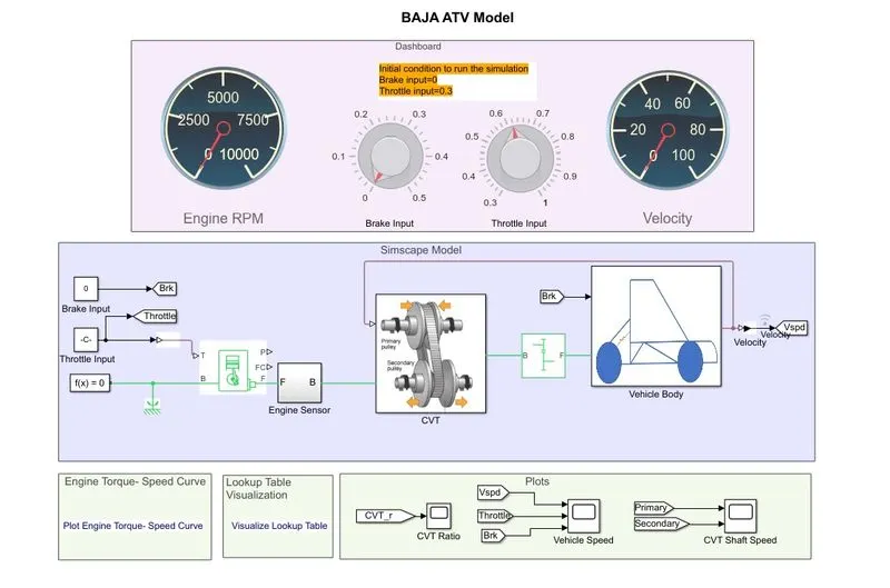
Figure (31) Baja ATV mapped model with dashboard
In this model the CVT ratio is varied according to velocity of the vehicle, velocity depend on the inputs provided by the user.
Plots:
1.Throttle and Brake Inputs
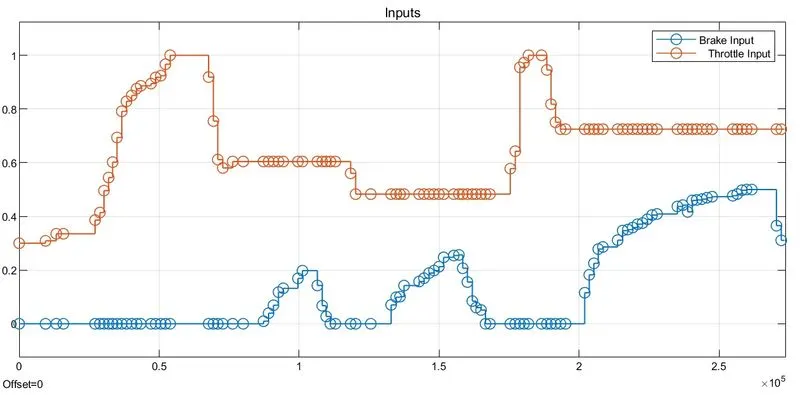
Figure (32) Inputs
The used defined inputs of throttle and brake is shown in graph. The values are changed between minimum to maximum in order find best performance of the ATV. Throttle value given 0.3 and brake 0 initially.
2.Velocity vs Time
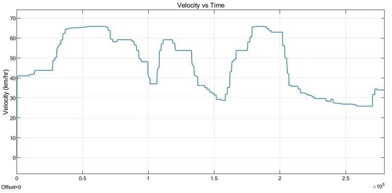
Figure (33) Velocity Graph
The maximum speed of this model is about 65 kmph. The velocity responds to throttle and brake inputs.
3.CVT shaft speed
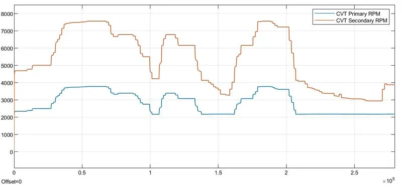
Figure (34) CVT Shaft Speed
The rpm of CVT shafts is shown higher values compared to all the models. Secondary shaft has reached highest rpm of 7500.
3.CVT Ratio
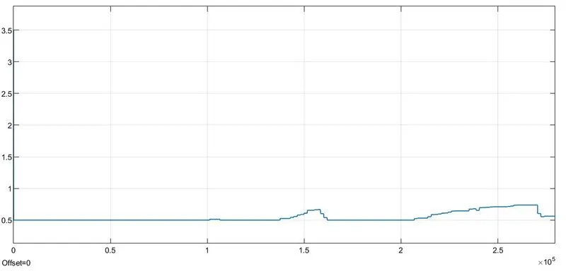
Figure (35) CVT Ratio Graph
Range of ratio in lied 0.5 to 1.
Conclusion: Performed system-level simulations on different models of a Baja all-terrain vehicle and made technical report moreover, identified that mapped models have the better performance.