Project
AIM:
To Carry out a system-level simulation of an all-terrain vehicle.
OBSERVATION:
- System-level simulation (SLS) - It is a collection of practical methods used in the field of systems engineering, in order to simulate, with a computer, the global behavior of large cyber-physical systems.
- Model of Baja ATV - The major simulink blocks used to in-vehicle simulation model
- Driver inputs - Throttle/brake profile
- Engine - system level model of spark ignition or diesel engine
- Transmission - Continuously variable transmission (CVT)
- vehicle body - Vehicle, tire and brake
COMMON BLOCKS USED:
1. Inertia block - The Inertia block represents an ideal mechanical translational inertia that is described with the following equation:
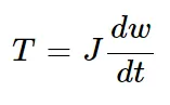
where:
-
T is inertia torque.
-
J is inertia.
-
ω is angular velocity.
-
t is time.
2. Gain block - The block multiplies the input by a constant value (gain). The input and the gain can each be a scalar, vector, or matrix. You specify the value of gain in the Gain parameter. The Multiplication parameter lets you specify element-wise or matrix multiplication.
3. PS terminator - Use the PS Terminator block to cap physical signal output ports that do not connect to other blocks.
4. PS signal constant - The PS Constant block generates a physical signal of a constant value. You specify the value and unit of the signal as the Constant parameter.
5. PS simulink converter - The PS-Simulink Converter block converts a physical signal into a Simulink output signal. Use this block to connect outputs of a Physical Network diagram to Simulink scopes or other Simulink blocks.
6. Simulink-PS converter block - The Simulink-PS Converter block converts the input Simulink signal into a physical signal. Use this block to connect Simulink sources or other Simulink .
7. Rotational Free End block - The block represents a mechanical rotational port that rotates freely, without torque. You can use this block to terminate mechanical rotational ports on other blocks that you want to leave unconnected.
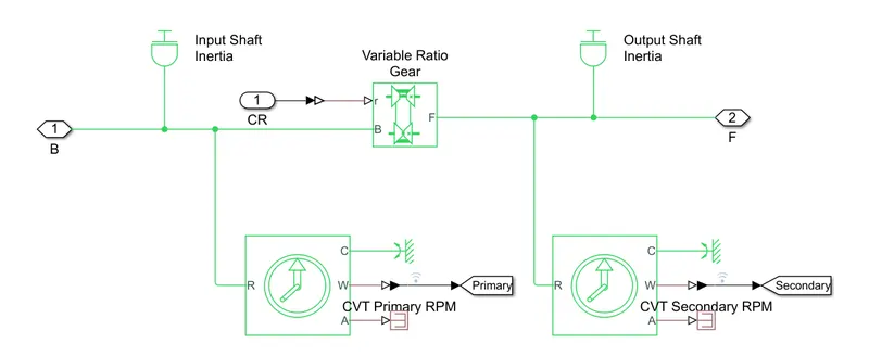
8. Variable Transmission Ratio block - The ratio of the follower to base angular speed decreases with gear ratio, and conversely the ratio of the follower to base torque increases with gear ratio. The variable gear is implemented using the Variable Ratio Transmission block which includes compliance.
9. Ideal Rotational Motion Sensor block - The block represents an ideal mechanical rotational motion sensor, that is, a device that converts an across variable measured between two mechanical rotational nodes into a control signal proportional to angular velocity or angle.
10. Gear block - It sets serve to transfer rotational motion and torque at a known ratio from one driveline axis to another. Simscape Driveline contains angular gears for transferring rotational motion and torque and linear gears, for transferring translational motion and force.
11.Mechanical Rotational Reference block - The block represents a reference point, or frame, for all mechanical rotational ports. All rotational ports that are rigidly clamped to the frame (ground) must be connected to a Mechanical Rotational Reference block.
12. Scope block - The blocks that display simulation results, but they differ in how you attach signals and save data. Simulation behavior for a Floating Scope and a Scope Viewer is identical, but you manage them differently in your model. Connect signal lines to a Scope block using input ports.
13. From block - The block accepts a signal from a corresponding Goto block, then passes it as output. The data type of the output is the same as that of the input from the Goto block. From and Goto blocks allow you to pass a signal from one block to another without actually connecting them.
14. Goto block - A block can pass its input signal to more than one From block, although a From block can receive a signal from only one Goto block. The input to that Goto block is passed to the From blocks associated with it as though the blocks were physically connected.
OBSERVATIONS:
Continuously variable transmission (CVT) :
CVTs differ from traditional automatic transmissions in that they don't have gears that provide "steps" between low and high speed operation. Instead, the majority of them work via a pair of variable-diameter, cone-shaped pulleys connected by a steel or ciomnposite belt.
The step-less nature of its design allows the CVT to work to keep the engine in its optimum power range, increasing efficiency and fuel mileage by delivering an infinte number of smooth transitions from low to high.
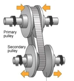
The CVT sub-system consists of the following blocks:
All terrain vehicle (ATV):
An all terrain vehicle (ATV) is defined as a motorized off road vehicle designed to travel on four low pressure or non-pneumatic tires, having a seat designed to be straddled by the operator and handlebars for steering control.
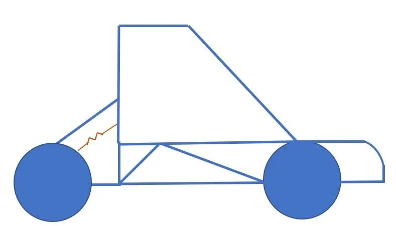
Vehicle body sub-system:
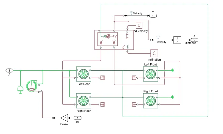
The vehicle body is defined to have a mass of 250 kg. The four wheels are connected accordingly and rpm of the secondary of CVT and brake input is given to the sub-system. The vehicle body is given zero inclination and wind velocity, The velocity is taken to the scope by using an output block (and goto block outside the sub-system).
The vehicle body sub-system consists of the following blocks under its mask:
Engine sensor sub-system:
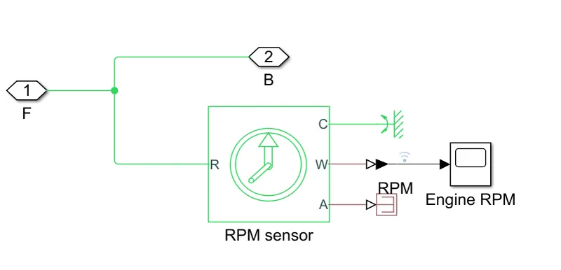
To connect the CVT and the engine, a simple gear with a gear ratio of 4 is used. The favourably transfers the torque and speed from the engine to the primary shaft of the CVT.
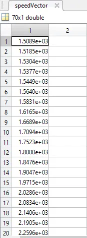
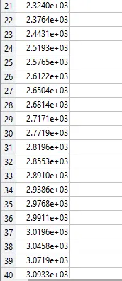
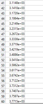
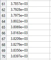
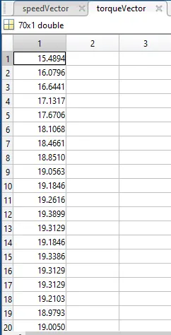
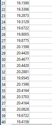
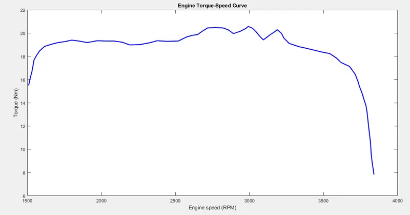
The generic engine block is used to model the engine of the vehicle. It is given the speed vector and torque vector by extracting the data points from the speed torque curve which represented in input signals below.
Lookup tables:
Lookup tables are used to map outputs based on input given. The output data corresponding to input is linked using a data array defined in the lookup table. The relationship between the input and output is unknown. Lookup tables improve accuracy and reduce time. Simulink can extract other data points by interpolation and extrapolation. It can be implemented by using the "lookup table" block.
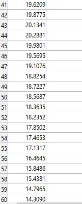
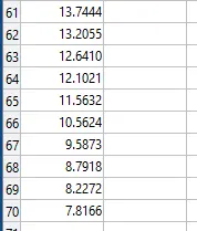
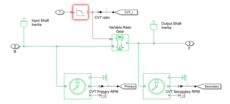
The lookup table used in the model gives the CVT ratio as output for respective input vehicle speed. The vehicle speed is fedback to the CVT sub-system where the CVT ratio is calculated using the lookup table block. The visualization of the lookup table used in two of the models under study is shown below:
PROCEDURE:
Study - 1:
BAJA ATV without lookup table
Case 1.1- Without dashboard
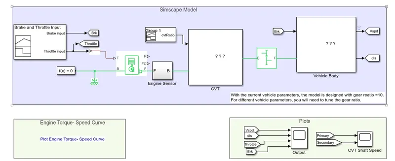
A simulink model of BAJA ATV model without dashboard is shown below.
Input signal
1. Torque vs speed for the engine
From the plot, it is observed that the maximum speed generated by the engine is at 2.9911e+03 rpm and maximum torque is 20.5703
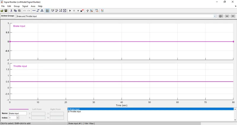
2. Signal builder for brakes and throttle
3. CVT Gear ratio input
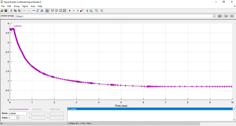
This is the simplest form of ATV. The inputs are given by the signal builder block and CVT ratio decreases linearly from 2.3(t=4) to 1.8(t=35). Here the brake input provided is zero for the entire time and throttle applied is 0.3 till 20 secs whereas full throttle is applied after 20 secs to the engine. The initial rpm of the engine is specified to be 2100 rpm. The results of the simulation are as follows
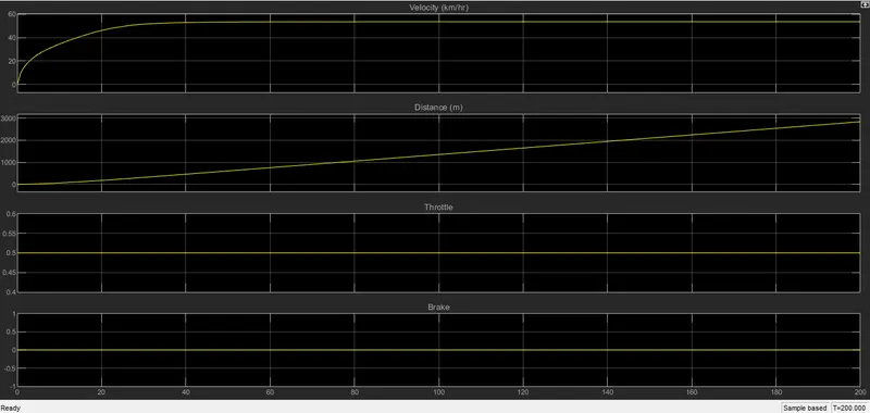
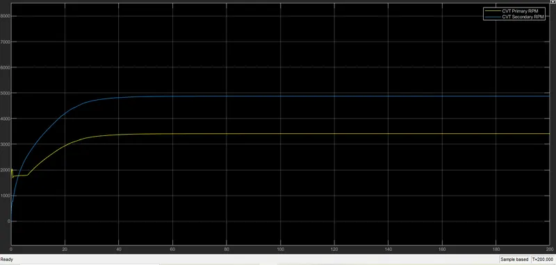
Here there are 3-time intervals of interest t=0 to t=4 (say T1), t=4 to t=20 (say T2), t=20 to t=35 (say T3) and t=35 to t=80 (say T4).
During T1, since the gear ratio and throttle are constant, there is linear variation between the primary and secondary rpm. During T2, the throttle is still constant, but now gear ratio starts decreasing. This increases the speed of the vehicle. At t=20 sec, the throttle input jumps to 1 and therefore the speed rises at an increases rate. And continues to rise owing to the decreasing gear ratio until t=35 sec. During T4 both CVT ratio and throttle is constant. Thus the speed does not increase beyond this time limit.
Case 1.2- With dashboard
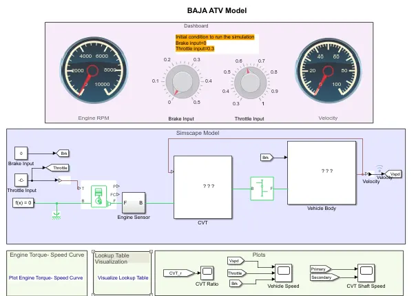
This model uses a dashboard to get input during the runtime. The minimum limit of the throttle is set to 0.3. CVT ratio decreases linearly from 2.3 (t=4) to 1.8(t=35).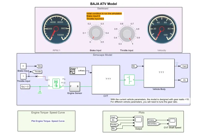
Throttle and brake input is given during runtime and the following results were observed:
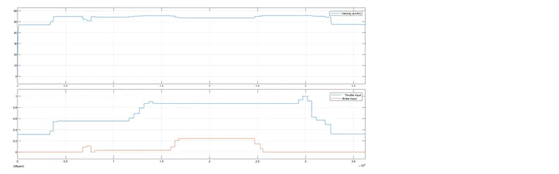
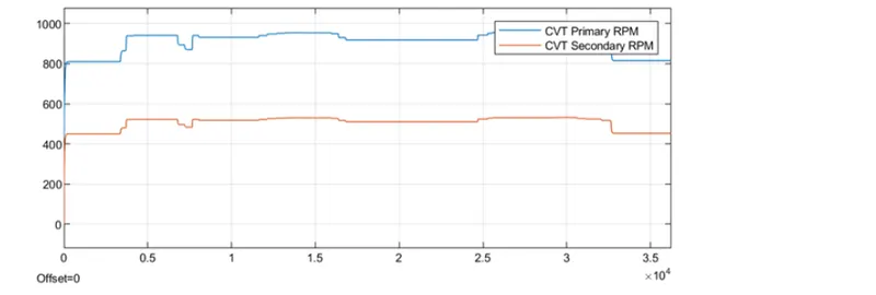
Increasing the brake input decreases the speed and increasing the throttle increases the speed and vice versa.
Study - 2:
BAJA ATV with lookup table
Case 2.1- Without dashboard
This model uses a lookup table inside the CVT subsystem which decides the gear ratio according to the velocity fed back to the subsystem.
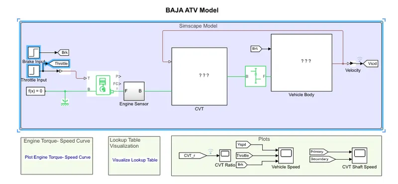
CVT sub-system:
The results are shown below:
The explanation for the results is similar to that of the first model. But the use of a lookup table improves the accuracy and smoothness of the curves.
Case 2.2- With dashboard
This model uses a dashboard to get input during the runtime and a lookup table for getting the CVT ratio.
RESULTS:
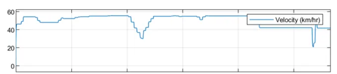
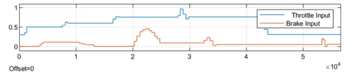
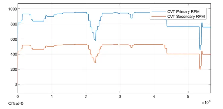
The speed varies as per the throttle and brake input. The secondary rpm follows the primary rpm linearly. Here, even if data for some values of velocity might be unavailable, the CVT ratio is still defined.
CONCLUSION:
- As the throtttle increases, the power input in the form of fuel to the engine increases and this in turn increases the rpm or velocity of the shaft.
- The output speed or the secondary rpm depends on brake (inversly proportional) and CVT ratio (inversly proportional) at that instant.
- Lookup tables can extrapolate and interpolate the missing data points of the curve.
- Dashboard elements can take instantaneous input to provide instantaneous output.
https://drive.google.com/drive/folders/1Kvu6entfbCagQ0pShLg7A8yhZ8ctZUsP?usp=sharing