Project - 2 - Meshing on the suspension Assembly
Aim: To mesh the geometry with in the given quality criteria and give connections where ever required.
1 Importing geometry and checking geometrical errors 2 Extracting mid-surface for components with thickness less than 5mm,
- Meshing the mid-surface with in the given quality criteria
- Meshing the components with thickness more than Smm
- Defining volume and generating tetra mesh
- Connecting the componerits by giving appropriate connections.
- Creating symmetry.
Procedure
Importing geometry and checking for errors:
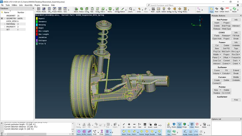
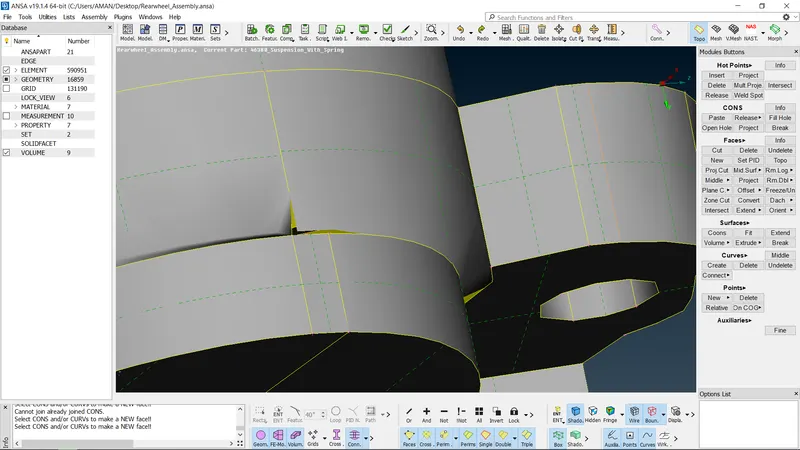
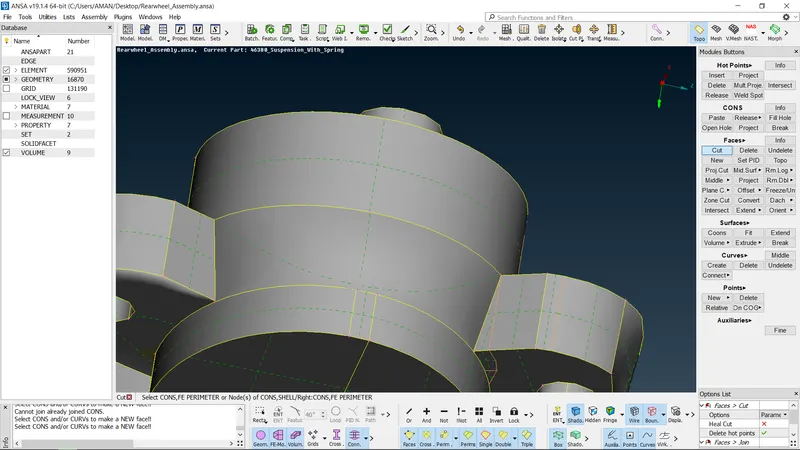
- To import geometry, select File >» Open» Click on the file. After importing topo should be performed to connect all the surfaces.
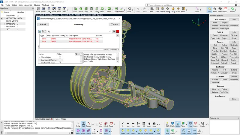
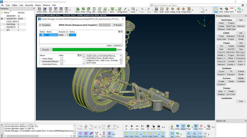
- To check for errors, select Checks Manager a> Geornetry » Execute. Errors can be rectified either by auto fix or by manually if any erors pop up.
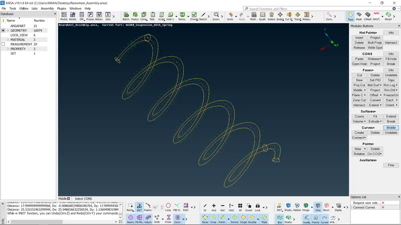
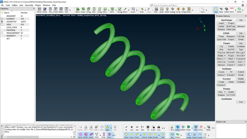
Representing spring with ID bar element:
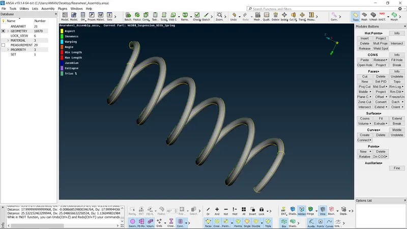
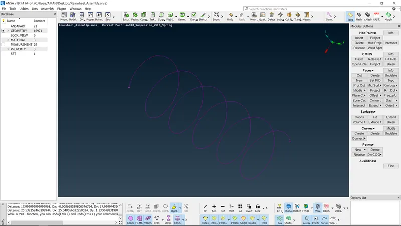
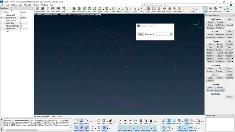
- To represent a spring with 1D bar element. curve is created along the center. After creating the curve, COG point is generated to define the orientation of the curve
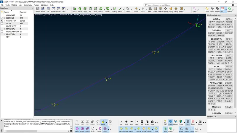
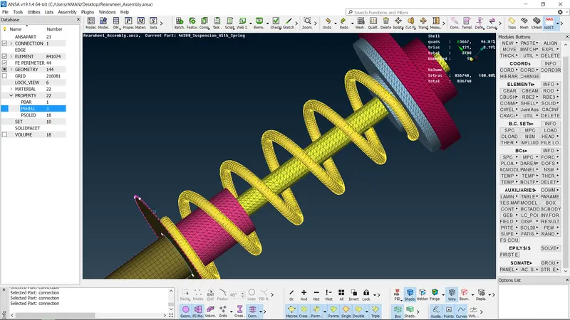
- Now switch to Nastran deck and select CBAR in elements and change the selection type to curve(box) select the COG of the curve. Now the element length is given and PID is created
- To give the area for the curve, press shift 7key and the radius of the curve is given and then click on. Now bar element is generated ANSA will automatically calculate the area By clicking on ok ID
- To represent the 1D element as solid, line element cross section as solids should be selected in quality parameters
Meshing the components with thickness mare than Smm:
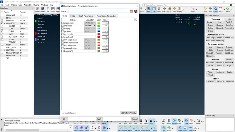
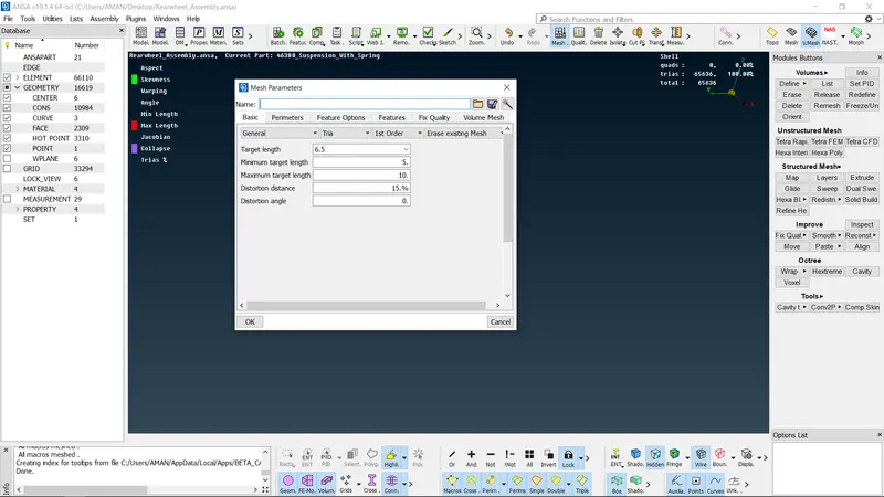
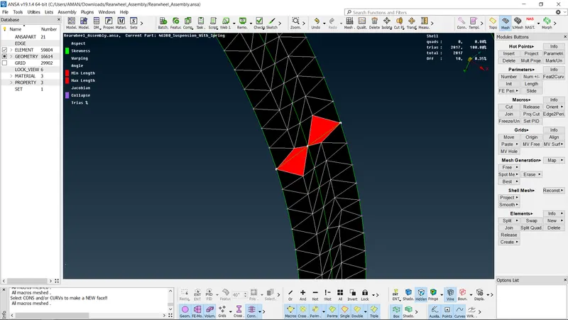
The quality criteria for the respective components should be given before meshing
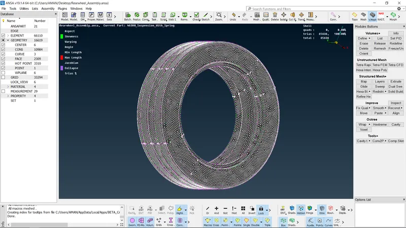
- Spot mesh is used to generate the mesh To generate mesh, select spot mesh present in mesh generation and then select the surface Spot mesh is the best option to generate the tetra mesh because it captures features perfectly
- For flat surfaces, tria can be used and for features, orthotria is used as element type.
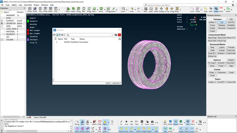
Defining volume and generating tetra mesh: To define the volume and generate solid mesh volume mesh deck should be selected
- To define volume, select Define Manual select the surfaces Volume defined components can be seen in list option present in volumes
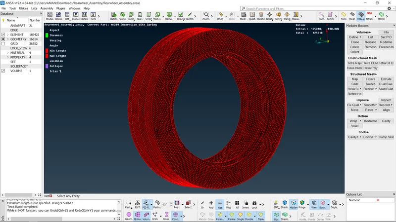
- To generate the solid mesh, select either tetra rapid or tetra FEM preset in unstructured mesh
- New PID solid should be created and solid mesh should be assigned to the respective
- There should be any kinks or raised edges in the solid mesh.
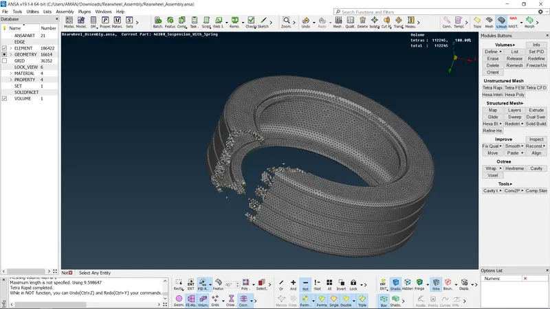
same work on other part
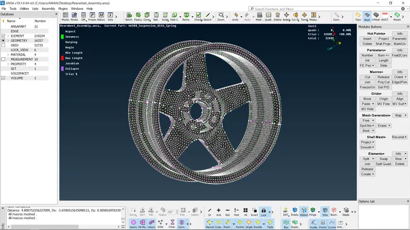
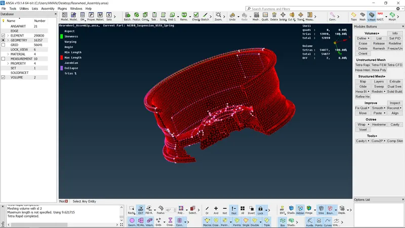
also check the collapse of all part
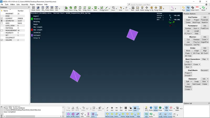
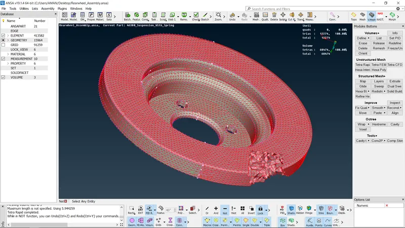
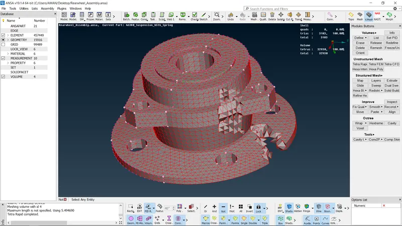
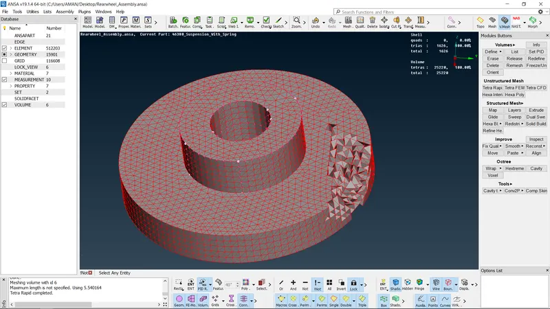
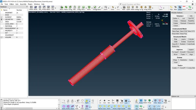
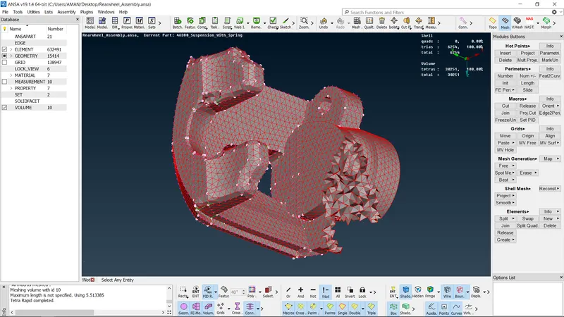
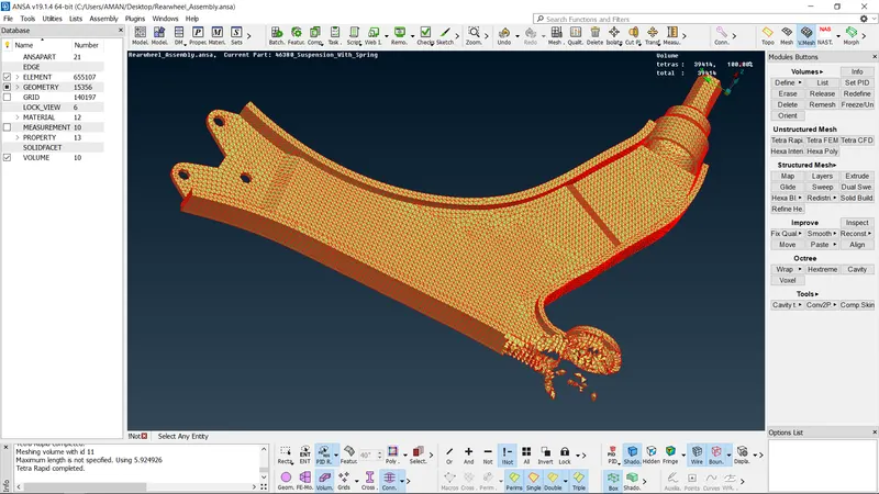
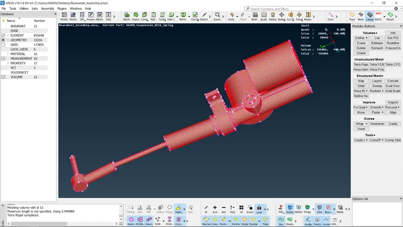
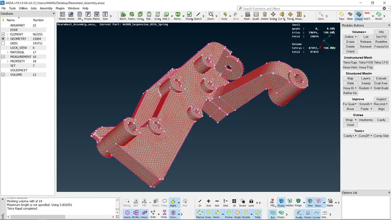
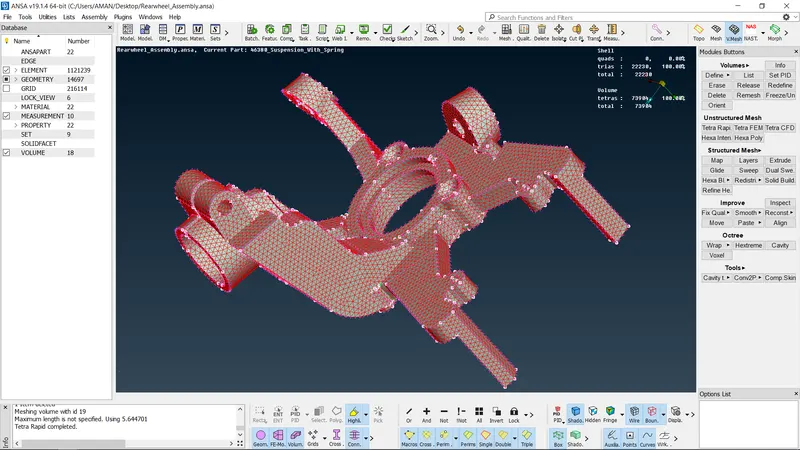
- Now the thickness is measured at different locations in the geometry Components with thickness less than Smm, mid-surface is extracted and mesh is generated
- For cormponents with thickness more than Smm, solid mesh is performed
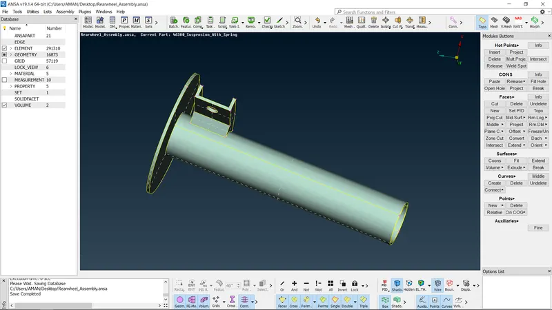
Extracting mid-surface for components with thickness less than Smm
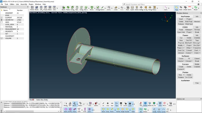
• To extract mid-surface offset is used. To use offset, select Offset Faces Select the face>» enter the mid value of thickness
Meshing the mid-surface with given quality criteria:
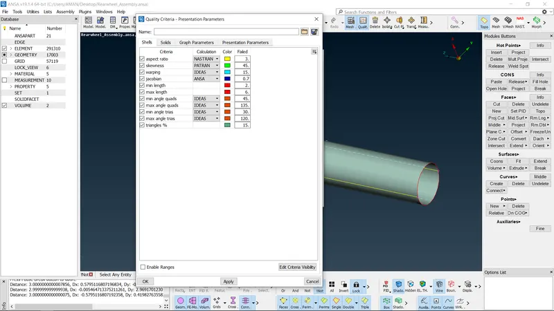
- The quality criteria for mid-surface components should be given before meshing the mid-surface.
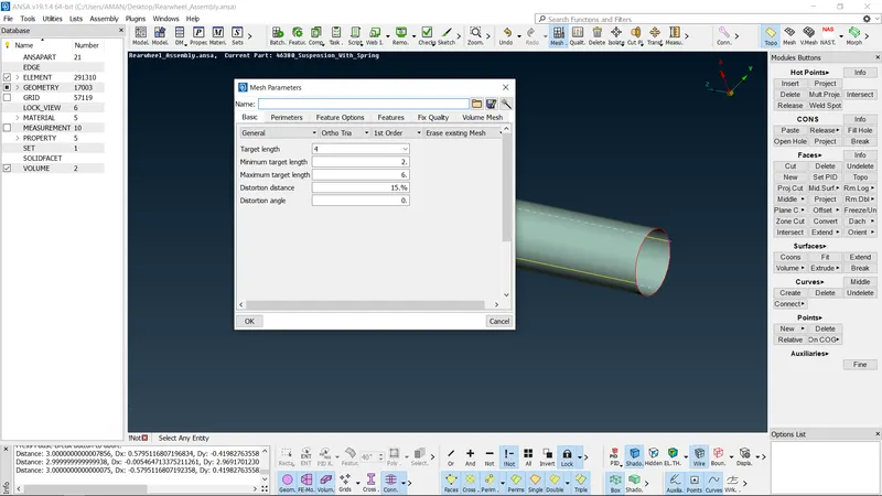
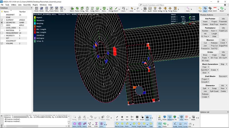
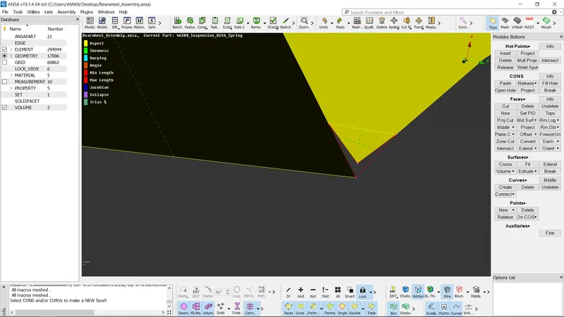
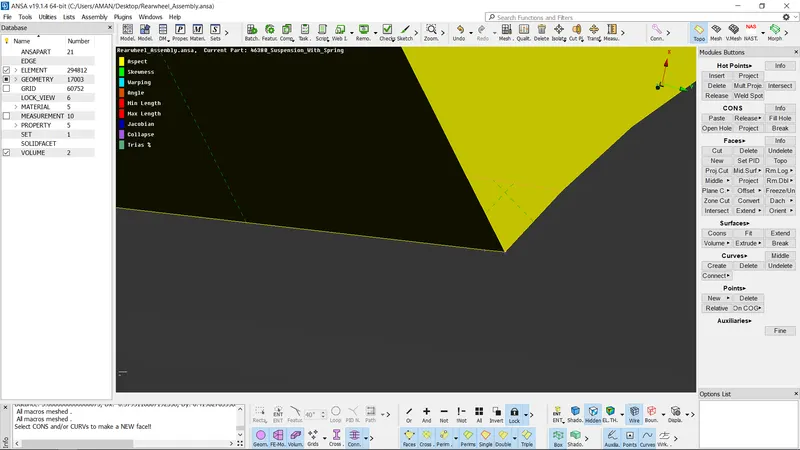
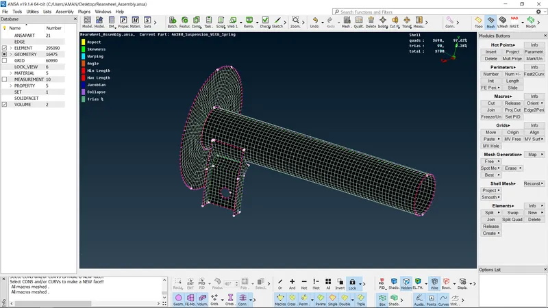
- Best mesh is used to generate the mesh To generate mesh, select Best mesh present in mesh generation and then select the surface
Connecting the components by giving appropriate connections:
- To give connections, Nastran deck should be selected
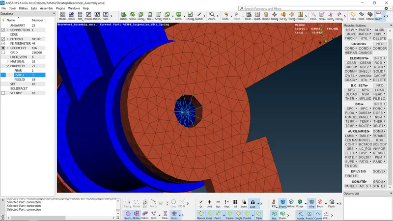
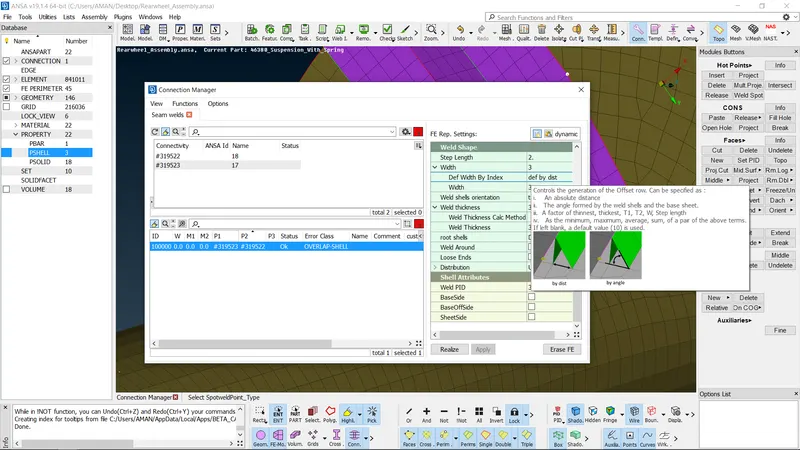
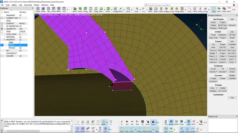
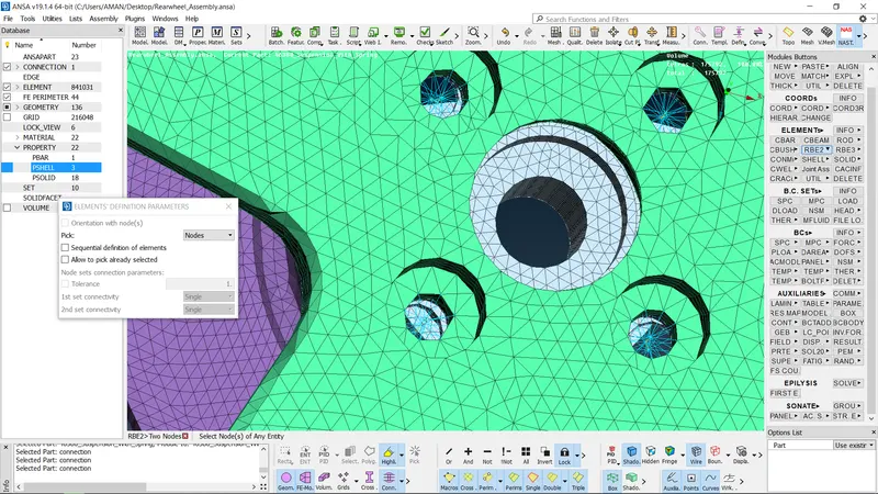
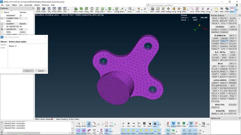
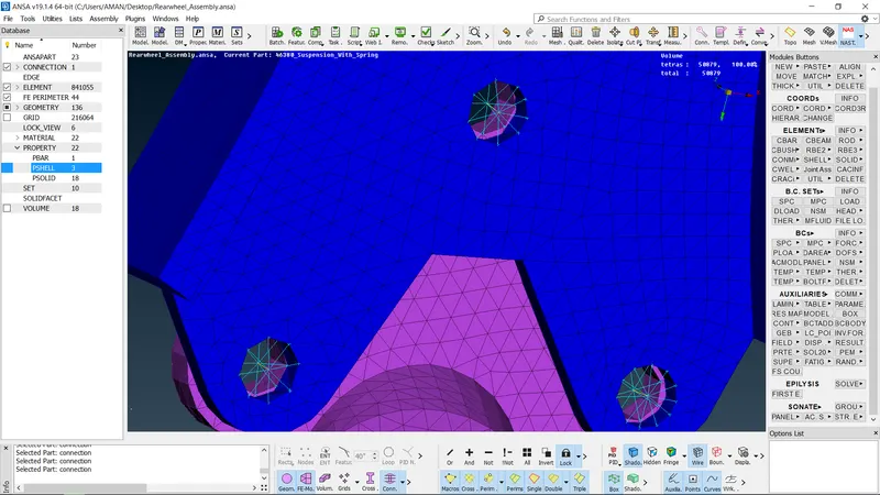
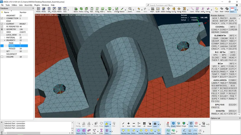
- In this model, sean weld cCnnection and RBE2 connections are given To give seam weld connection, a curve is generated along the FEA and the curve is converted into seam line using convert option present in assembly deck
- After converting the curve to seam weld, connection manager is opened and seamline is selected Now the PID of both the components are given in connection manager and in FE rep type overlap shell is selected
- Now the searm weld connection is generated
Creating Symmetry:
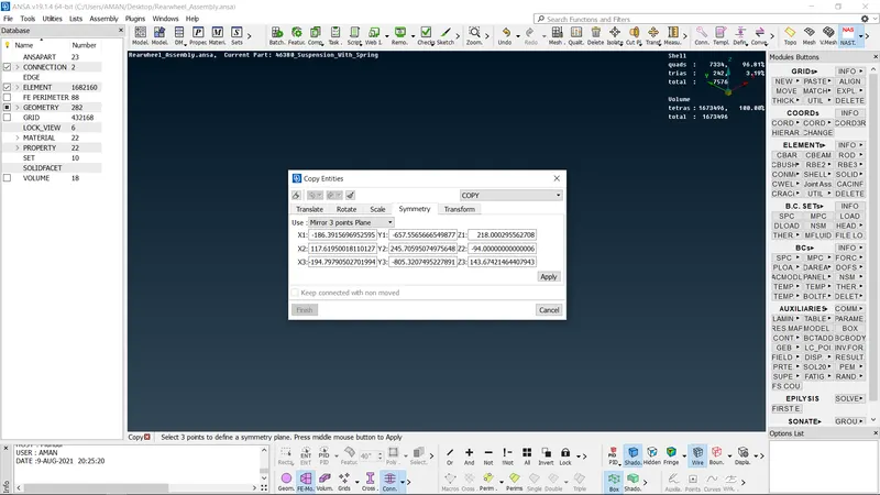
- To create the symmetry, transform option present in utilities deck is used Select transform » copy >> entities >> symmetry > mirror 3 points plane » select any 3 points on the entities and click ok.
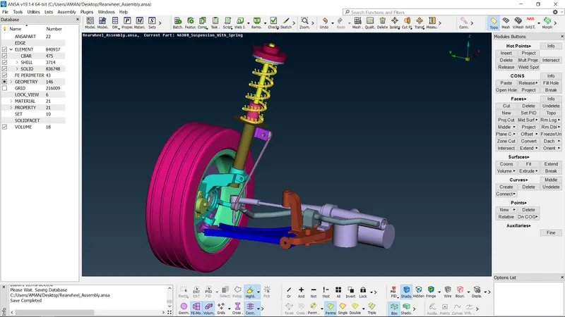
Final model
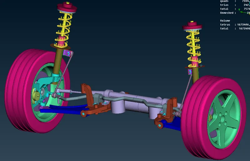
Conclusion:
• For the given rear suspension model, geometry cleanup is performed, mesh is generated with in the given quality.criteria and appropriate connections are made