Project - 2 - Meshing on the suspension Assembly
Aim:- For the given assembly, check for the geometrical errors and mesh with the given element Quality criteria. After meshing the component the thickness has to be assigned for mid surfaces. Use tetra elements to model non-uniform thickness components. Also use Appropriate connections to connect the component as suggested in the Project-2 video (Use PBAR elements to model suspension spring). At last perform Symmetry command to reflect the half finished model to the other side.
Write a detailed report on your meshing process and also mention which method you used to extract the mid-surface along with the reason.
Common Note:
- Use Volume mesh for Tyre and Rim with below Quality criteria. (Use Tria Element)
- Use mid surface only when the thickness is uniform and less than 5 mm. (Use Mixed elements)
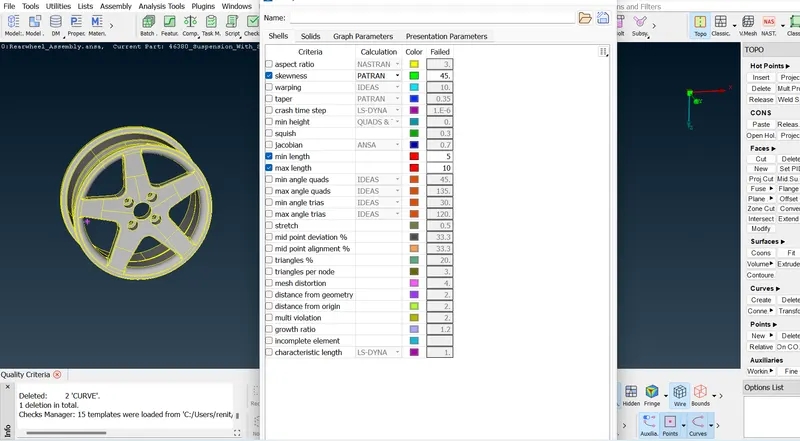
Quality Criteria for Surface Meshing of Tyre and Rim (Element type: Tria) :
|
S.No |
Quality Criteria |
Value |
|
1 |
Target/Average length |
6.5 |
|
2 |
Minimum Length |
5 |
|
3 |
Maximum Length |
10 |
|
4 |
Skewness |
45 |
Quality criteria for Surface Meshing of Non Uniform thickness components other than Tyre and Rim (Element type: Tria) :
|
S.No |
Quality Criteria |
Value |
|
1 |
Target/Average length |
4 |
|
2 |
Minimum Length |
2 |
|
3 |
Maximum Length |
6 |
|
4 |
Skewness |
45 |
Quality Criteria for Volume meshing of all Non Uniform thickness components (Element type: Tetra Elements):
|
S.No |
Quality Criteria |
Value |
|
1 |
Tet-collapse |
0.2 |
Quality criteria for Mid surfacing of Uniform thickness part which has thickness less than 5 mm (Element type: Mixed elements) :
|
S.No |
Quality Criteria |
Value |
|
1 |
Target/Average length |
4 |
|
2 |
Minimum Length |
2 |
|
3 |
Maximum Length |
6 |
|
4 |
Aspect |
3 |
|
5 |
Warpage |
15 |
|
6 |
Skewness |
45 |
|
7 |
Jacobian |
0.7 |
|
8 |
Minimum Quad Angle |
45 |
|
9 |
Maximum Quad Angle |
135 |
|
10 |
Minimum Tria Angle |
30 |
|
11 |
Maximum Tria Angle |
120 |
Procedure :-
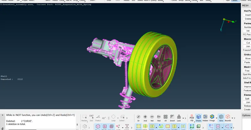
Step 1 :- Import the model.
File -open -select the model -open.
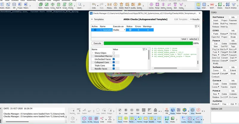
Step 2 :- Checks for geometry.
geometry -checks -execute.
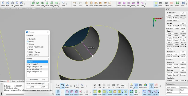
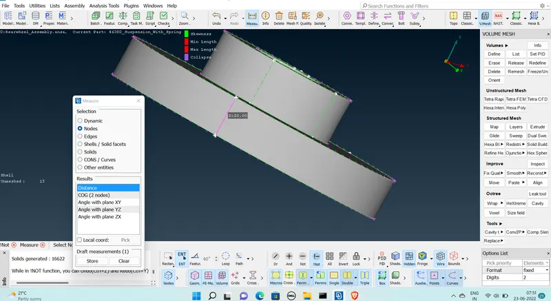
Step 3 :- Measuring the thickness .
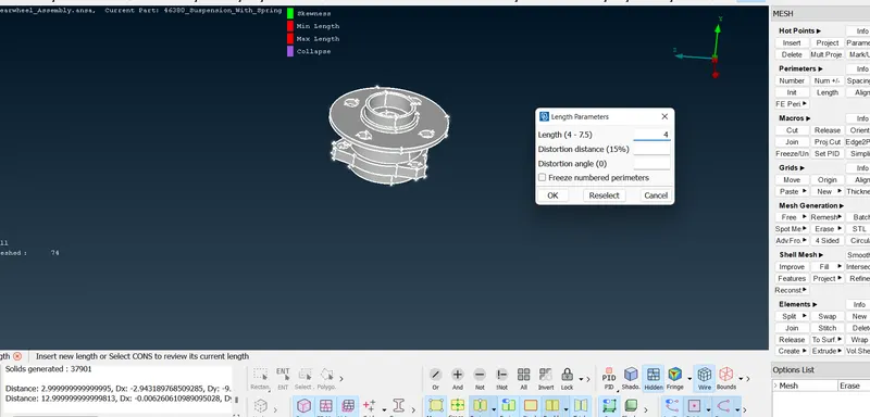
Step 4:- giving length
Step 5 :-Assigning Quality criteria to the model.
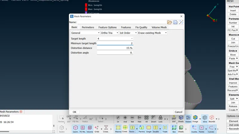
Step 6 :-Assigning Quality parameters .
Step 7 :- Generating Meshing (Tria)
1.1) Generating meshing Non Uniform thickness components
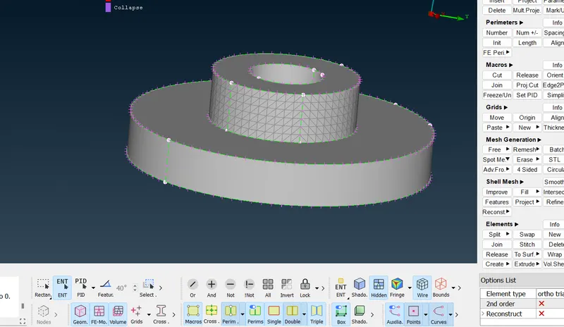
1.2) Reconstruction
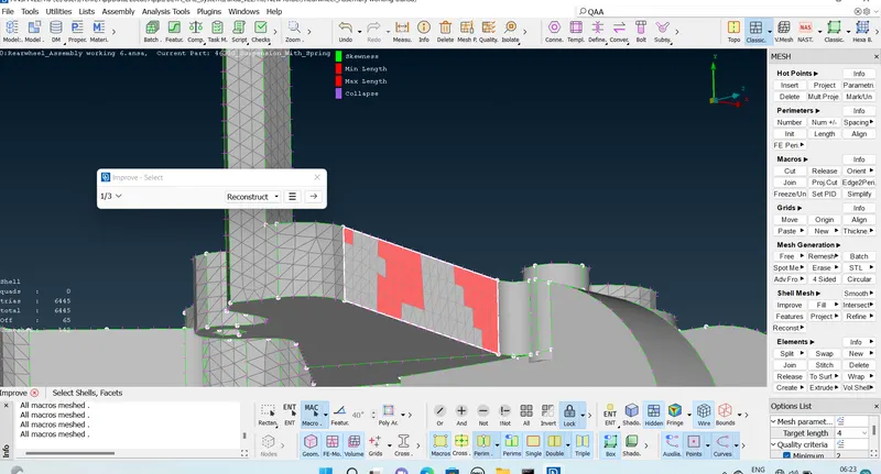
1.3) Generated Mesh
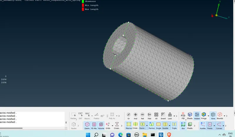
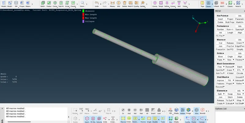
1.4) Volume meshing of all Non Uniform thickness components
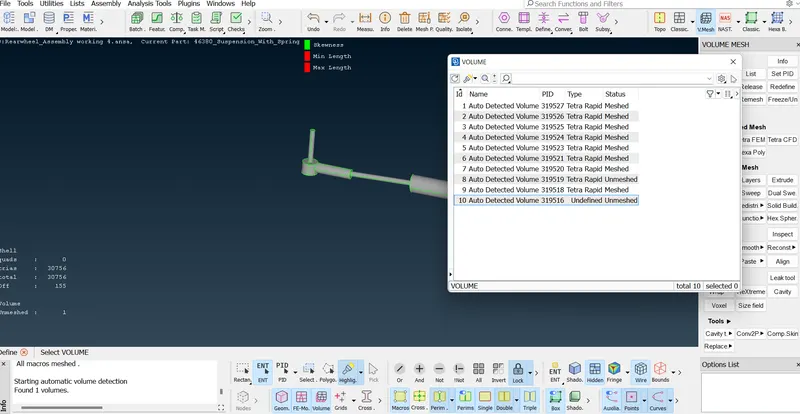
Define the volume :
voume mesh -volumes -define -visible-ok
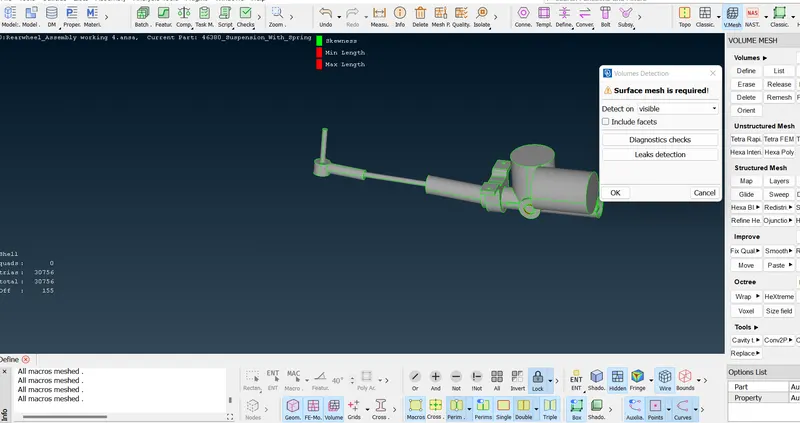
Defined Volume
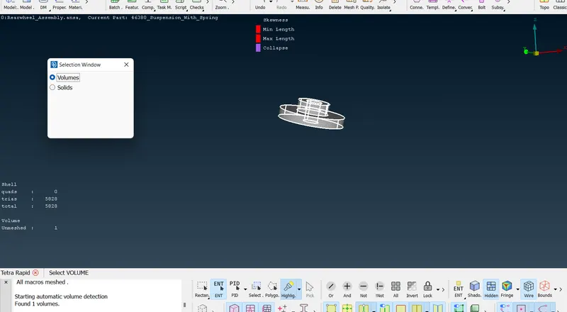
1.5) Generating tera-rapid unstructured mesh.
vomume mesh -unstructured mesh -tetra-rapid -select the volume - ok.
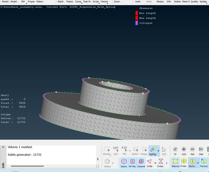
1.6) Generated volume mesh.
2 ) Mid surfacing of Uniform thickness part which has thickness less than 5 mm
2.1) Taking mid surface
Topo -Faces -Mid surface - skin.
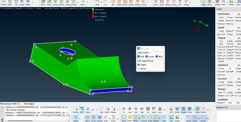
2.2) Generated Mid surface .
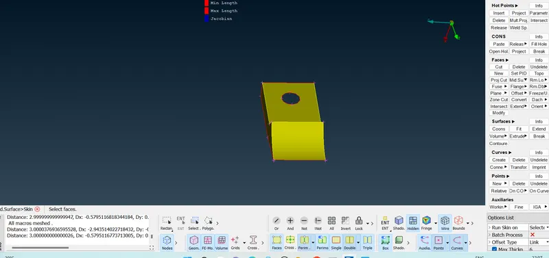
2.3 ) Assigngn Quality Critera
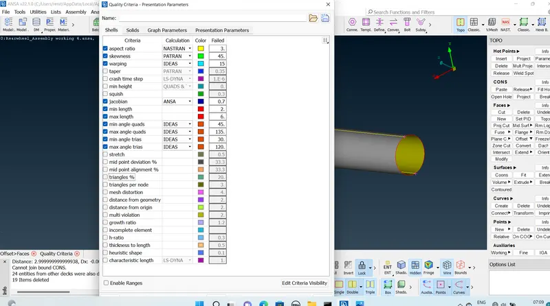
2.4) Generating Mesh
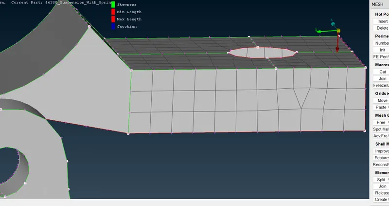
Smoothig .
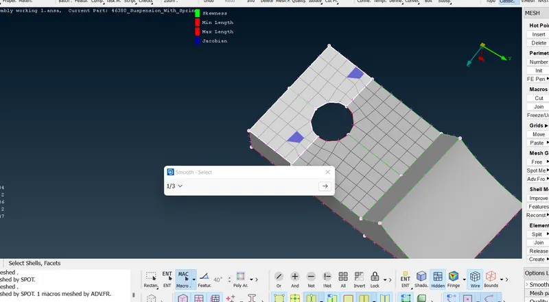
2.5)Generating Mid surface using offset .
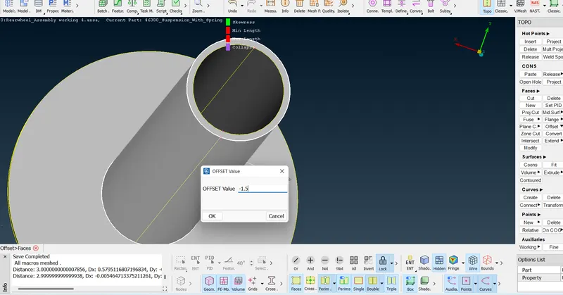
2.6) mid surface generated .
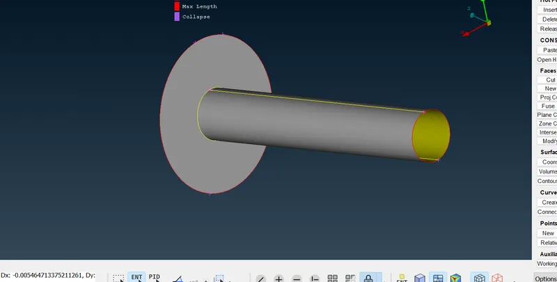
2.7) Meshing the mid surface using Mixed Element type.
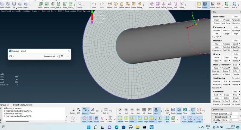
3)Surface Meshing of Tyre and Rim
3.1)Mesh parameters
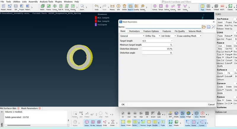
3.2)Quality Parameters.
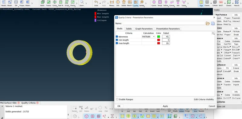
3.3)Generating Mesh (Tria)
classic mesh-mesh generation -spot mesh -select the surface -mesh.
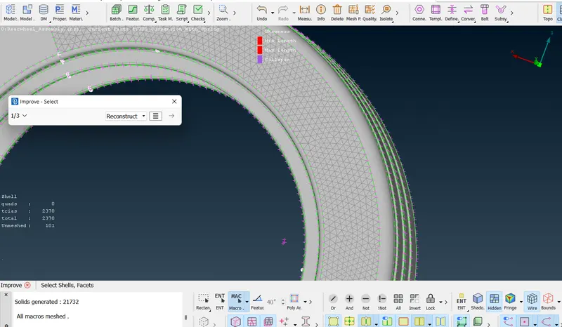
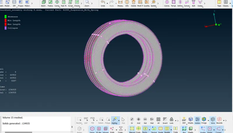
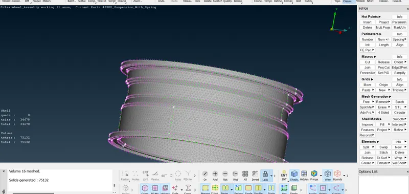
3.4)Generating Volume Mesh.
voume mesh -volumes -define -visible-Defined Volume -tetra Rapid
3.5)Quality poarameters for volume mesh.
tet collapse -0.2
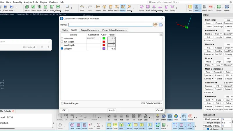
Tet collapse failure
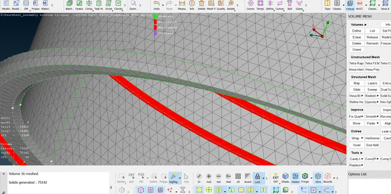
Passes Tet collapse .
Tyre
Rim
4)Modeling suspension Spring.
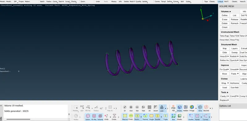
4.1) Creating Curve .
Topo- Curves -middle -selec t the two lines -create mid curve.
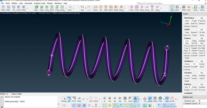
4.2) Connect the curves into one curve .
Topo- Curves-Multi -select all curves -ok
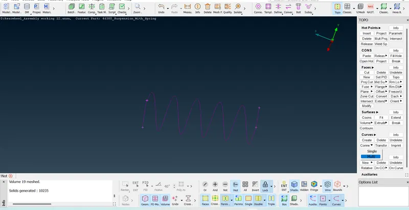
4.3)Generating 1D elements
Create 3D node :_ Topo -Points - COG -selelt the spring
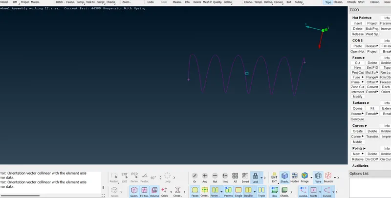
Nastran - Cbar - curve box -select the spring -select the 3D Points
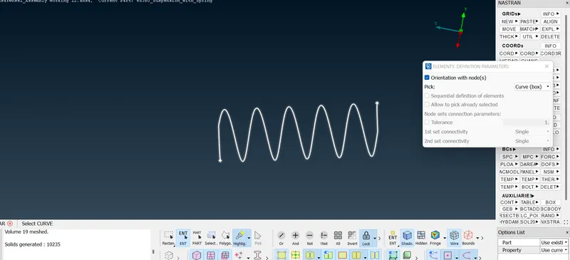
specify the element lenght -create new property -Give radius -Area
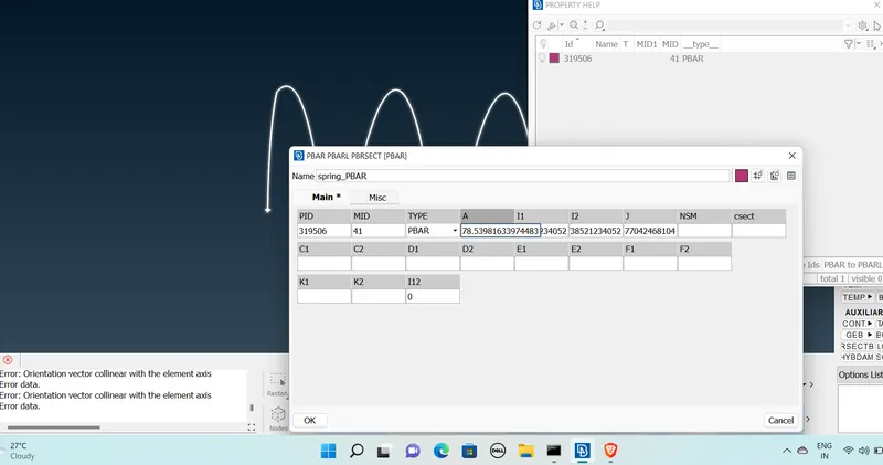
Created 1D element .
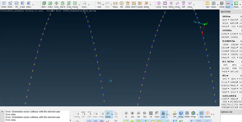
Line elemental crossection as solid
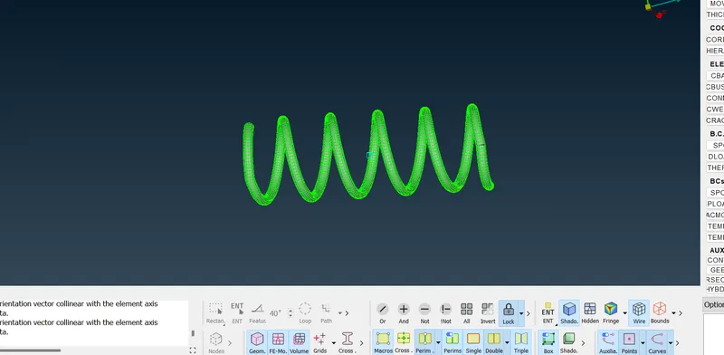
Meshing Completed
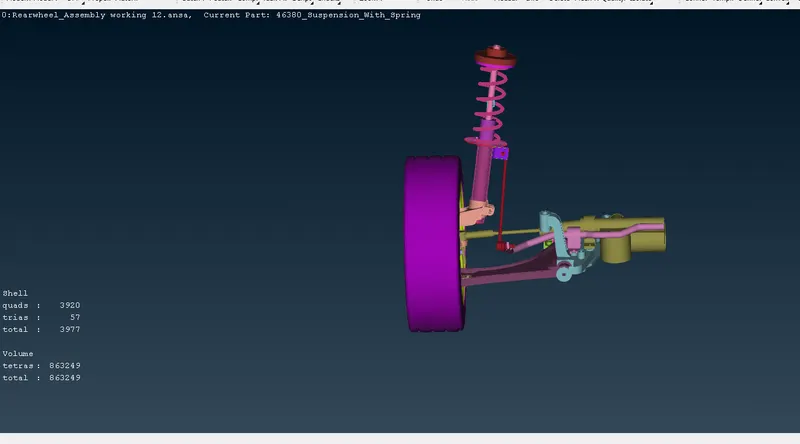
5) Creating Connectors.
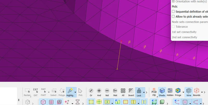
RBE2 with 2 Nodes
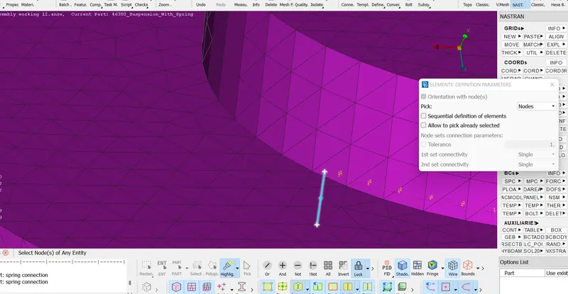
RBE2 Connected.
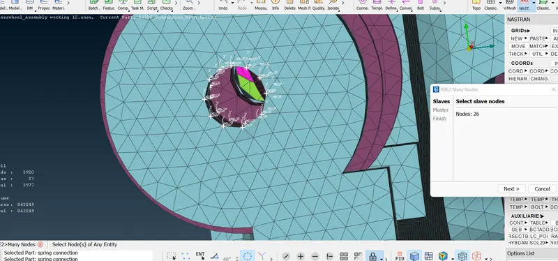
RBE2 with Many Nodes .
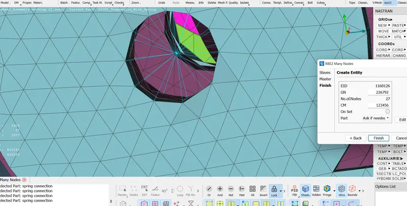
Created Cluster RBE2
6)Reflection
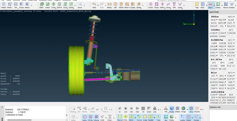
Tranfrom -copy -select the entites -summetry -mirror -ok

Final Model :-
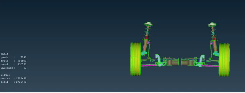
Result :- Given assembly, checked for the geometrical errors and mesh with the given element Quality criteria.After meshed thec component thickness has to be assigned for mid surfaces. Use tetra elements to model non-uniform thickness components. Also use Appropriate connections to connect the component an d performed Symmetry command to reflect the half finished model to the other side
Learing Outcomes :-
*Learned about different types of generating mid surface .
*Learned about generating 2D meshing and Volume Meshing in same assemply.
*Learned about to model suspension spring.
*leaned about connection.
Completed Model :-
https://drive.google.com/file/d/1bil2XI36MLAZTEPNqpTnTUgTfpUNpL4g/view?usp=sharing
Thanks
Renith Balachandran m