Project - 2 - Meshing on the suspension Assembly
I'm uploading the google drive link for the model because the model size is too high it is not getting upload in the mentioned area. I have tried multiple times to load it in the specified area to upload the model but it is not happening.
Link for the model:
https://drive.google.com/file/d/1JYYLWczvqzzGBHpZ92fDewbOSCsFl9A_/view?usp=sharing
Objective:
For the given assembly, check for the geometrical errors and mesh with the given element Quality criteria. After meshing the component the thickness has to be assigned for mid surfaces. Use tetra elements to model non-uniform thickness components.
Also, use Appropriate connections to connect the component as suggested in the Project-2 video (Use PBAR elements to model suspension spring). At last, perform Symmetry command to reflect the half-finished model to the other side.
Common Note:
- Use Volume mesh for Tyre and Rim with the below Quality criteria. (Use Tria Elements)
- Use mid surface only when the thickness is uniform and less than 5 mm. (Use Mixed elements)
Surface meshing for Tyre and Rim with Trias and Ortho trias for Tyre & Rim and converting them into 3D Tetra mesh:
Quality Criteria for Surface Meshing of Tyre and Rim (Element type: Tria) :
|
S.No |
Quality Criteria |
Value |
|
1 |
Target/Average length |
6.5 |
|
2 |
Minimum Length |
5 |
|
3 |
Maximum Length |
10 |
|
4 |
Skewness |
45 |
Procedure:
- Open the Ansa software and import the Rearsuspension_assembly model into the software.
- Apply the target element length on the selected perimeter segments or macro areas to apply the mesh as per the given element criteria & also for the better mesh flow on the model.
- To apply the target length, change to the Mesh mode from Topo mode, select the Length option in the Perimeters, select the whole surface & enter the given target element length value and click the middle-click on the mouse to confirm the task.
- There are 16 components present in the given Rearwheel_suspension model, click on the model browser on the left side of the graphic area at the top to select the component to be worked on and hide all the rest of the components. For example, select the Tyre component and hide all the rest of the components.
- After selecting the required component, check the model if the model has any geometrical errors like needle faces, triple cons etc. If any errors like these present in the given model try to remove them with the help of the CHECKS tool present at the top of the graphic area.
- Click on the CHECKS tool from the dropdown list select the Geometry option. Upon entering into the Geometry window, check on the Active button and change the option for the Execute on option to Visible and click on the Execute button. The errors present in the model will be displayed.
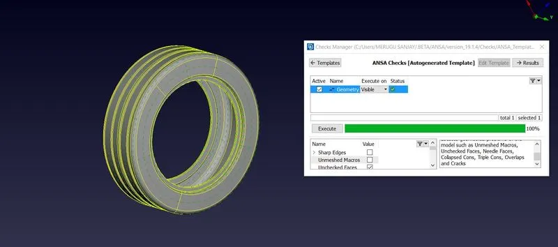
THE TYRE COMPONENT IS FREE OF ERRORS WHEN CHECKED
- Click on the errors one by one and right-click and select the option Fix which means the error will be automatically fixed by Ansa if possible and if it is not possible it needs to be fixed manually.
- After clearing all the errors, try to mesh the component using the Tria & Ortho Tria elements.
- Enter the values for the given component in the Mesh parameters window, change the type of the elements from Mixed to Ortho Tria & also in the Quality criteria or press the F11 function key to open the window enter the values for the likes of Minimum length, Maximum length and for the Tet collapse.
- After applying the target element length on the Tyre component try to mesh the component. Keep the Mesh mode as it is and click on the Best mesh in the Mesh Generation.
- Select a face on the component and middle-click to generate the mesh. The mesh generated on the selected face, if the mesh pattern was not good try to reconstruct the mesh by using the Reconstruct tool in the Shell Mesh tools.
- Wherever there are the curved regions try to apply the Ortho Tria elements mesh and apply the Tria elements mesh on the flat surfaces.
- If there are any mesh elements failing for the given quality criteria, try to clear them by using the different tools.
- For example, if any less number of elements failing for the Minimum Elements Size try to clear them manually by using the Split option in the Elements tools by splitting the elements.
- In the Mesh mode and at the bottom there are the Elements tools present. In these Elements tools, there are options like Split, Join, Swap etc are present use these tools to clear the mesh quality manually.
- After splitting the elements, the mesh pattern will be disturbed and then use the Smooth tool in the Shell Mesh tools to smoothen the disturbed mesh pattern. If there are a huge number of elements that are failing for the quality try to use the Reconstruct tool present in the Shell Mesh tools.
- After applying the 2D Tria and Ortho Tria mesh, apply the 3D Tetra mesh on the component.
- Click on the Volume Mesh deck, select the Volumes and click on the Define option.
- In the popup window, in the work on option change the Whole DB to visible option & there is a property created in the popup window and it shows the mesh is undefined.
- Right-Click on the property created and select the Remesh option and select the Tetra FEM algorithm from the list of algorithms available.
- Middle-click to apply the Tetra mesh with Tetra FEM algorithm.
- After applying the Tetra mesh, check for the number of OFF elements and also for Tet Collapse. Clear all the tet collapse failed elements.
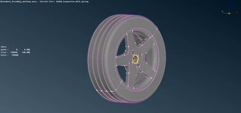
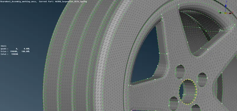
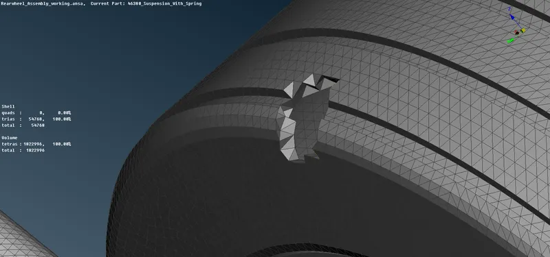
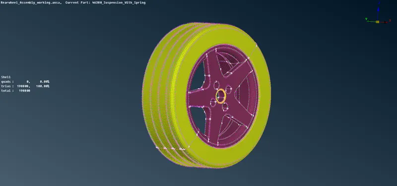
THE TYRE AND RIM HAS BEEN MESHED WITH 2D MESH AND CONVERTED TO 3D TETRA ELEMENTS
Mesh the remaining non uniform thickness components other than tyre and rim in the same way that tyre and rim has been meshed but different quality criteria.
Surface meshing for the given components other than tyre and Rim with Trias and Ortho trias and converting them into 3D Tetra mesh:
The quality criteria for the surface meshing of components other than tyre and rim:
|
S.No |
Quality Criteria |
Value |
|
1 |
Target/Average length |
4 |
|
2 |
Minimum Length |
2 |
|
3 |
Maximum Length |
6 |
|
4 |
Skewness |
45 |
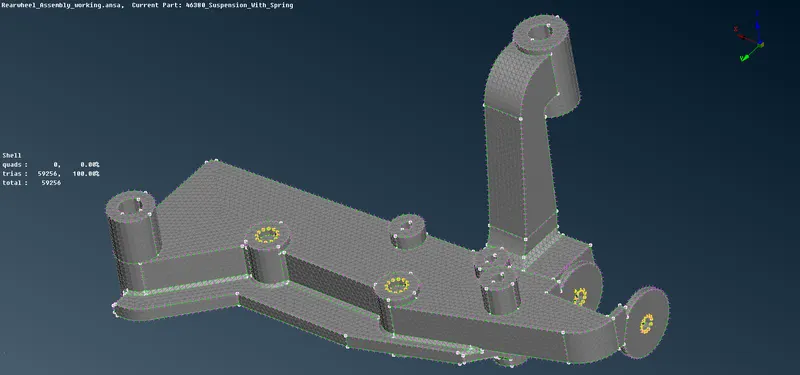
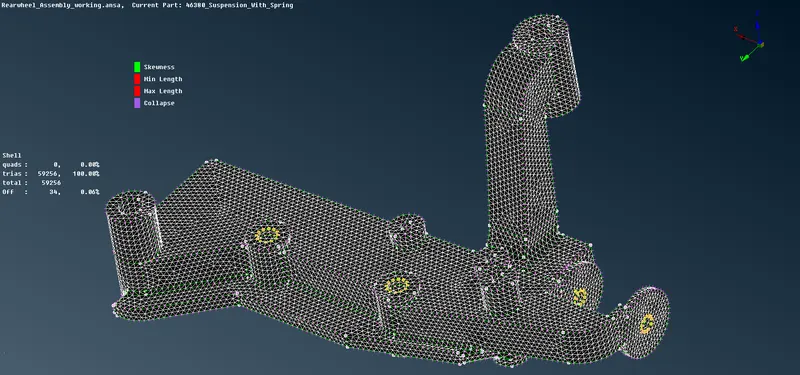
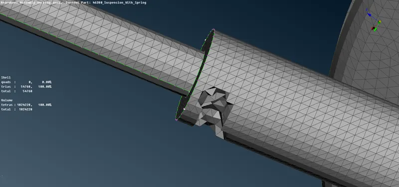
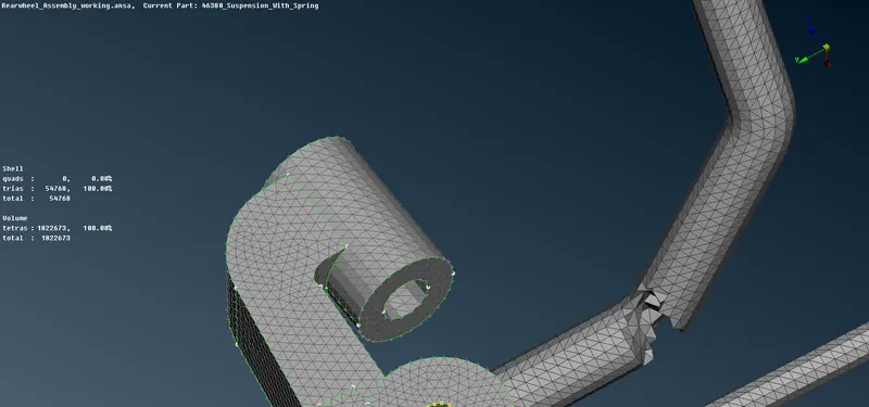
COMPONENTS OTHER THAN TYRE AND RIM WITH 3D TETRA MESH
Applying 2D Mesh for some components having thickness less than 5mm.
Quality criteria for Mid surfacing of Uniform thickness part which has a thickness less than 5 mm (Element type: Mixed elements) :
|
S.No |
Quality Criteria |
Value |
|
1 |
Target/Average length |
4 |
|
2 |
Minimum Length |
2 |
|
3 |
Maximum Length |
6 |
|
4 |
Aspect |
3 |
|
5 |
Warpage |
15 |
|
6 |
Skewness |
45 |
|
7 |
Jacobian |
0.7 |
|
8 |
Minimum Quad Angle |
45 |
|
9 |
Maximum Quad Angle |
135 |
|
10 |
Minimum Tria Angle |
30 |
|
11 |
Maximum Tria Angle |
120 |
Procedure:
- After meshing the Tyre and Rim and also the other parts with Trias and Ortho trias along with the given quality criteria. There are 3 components in the model where the thickness of those surfaces is less than 5mm.
- The surfaces which are less than 5mm needed to be meshed with Mixed elements. The surfaces should be meshed with Mixed elements along with the given quality criteria.
- Firstly, the midsurfaces of the components are to be extracted, use the Offset tool to extract the midsurface manually. Before using the Offset tool, measure the thickness of the component.
- After measuring the thickness of the component, use the Offset option to extract the midsurface from the given component.
- After extracting the midsurface from the given component try to mesh the extracted midsurface.Before applying the mesh on the midsurface component, try to apply the given target element length on the midsurface.
- To apply the length, change to the Mesh mode from Topo mode, select the Length option in the Perimeters, select the whole midsurface, enter the given target element length value and click the middle-click on the mouse to confirm the task.
- After applying the target element length on the midsurface try to mesh the component. Keep the Mesh mode as it is and click on the Best mesh in the Mesh Generation.
- Select a face on the midsurface and middle-click to generate the mesh. The mesh generated on the selected face, if the mesh pattern was not good try to reconstruct the mesh by using the Reconstruct tool in the Shell Mesh tools.
- If there are any mesh elements failing for the given quality criteria, try to clear the failed elements by using the split, join, paste etc options available in the Mesh deck.
- After meshing the Mid surface, Thickness must be assigned to the Midsurface.Use the Set PID tool to apply the Thickness by creating a Property ID.
- Click on the Set PID tool in the Faces tools in the Topo deck and select the whole surface because the total surface is of the same thickness, a pop-up window will be displayed in that enter the thickness value and select a proper colour in the Colour-edit and click on the OK button.
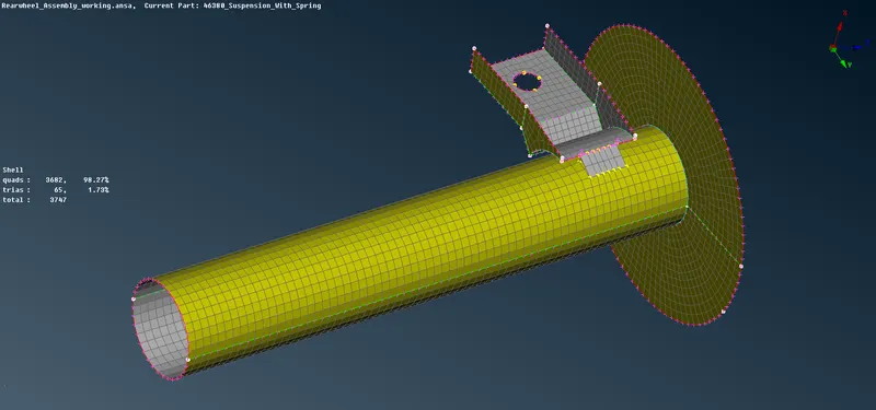
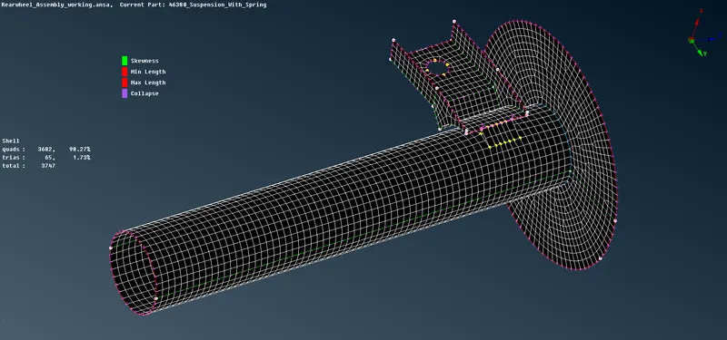
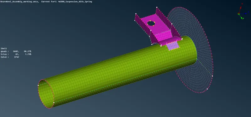
THE 3 COMPONENTS HAVE BEEN MESHED WITH 2D ELEMENTS ON THE MIDSURFACES
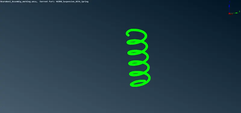
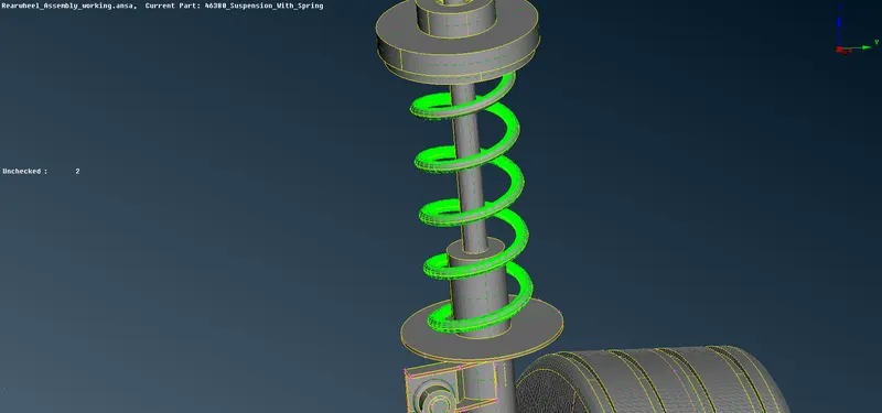
THE COILSPRING HAS BEEN MESHED ACCORDING TO THE GIVEN ARTICLE
Connections:
After meshing all the components with 3D Tetra mesh, the components should be connected by using different connections in the Nastran deck.
- Identify the areas where the connections needed to be deployed.
- Using the tools in the Nastran deck make good connections for the components wherever required.
- Create a RBE 2 elements between tyre and rim and the other parts associated with it.
- Firstly, isolate the components where the connections should be created.
- Click on the RBE2 option in the Elements tools and select the many nodes option in the available options to establish a RBE2 cluster elements.
- Select the area by Loop option by selecting all the nodes in the circular area click Ok to confirm to establish a cluster rbe2 elements.
- After capturing with RBE2 elements try to create a connection between already created connection with the same RBE2 elements by using the Two nodes option in it.
- Select the Two nodes option then select the master node of the previously created RBE2 elements and click Ok to confirm the procedure.
- Create this type of connection wherever required on the given model.
- Make sure to properly connect the components properly by selecting the right area.
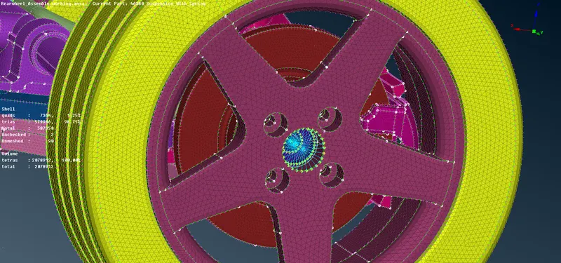
RBE2 ELEMENTS ARE CREATED WITH TYRE, RIM AND OTHER ASSOCIATED PARTS
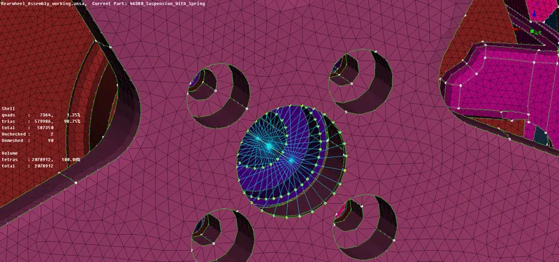
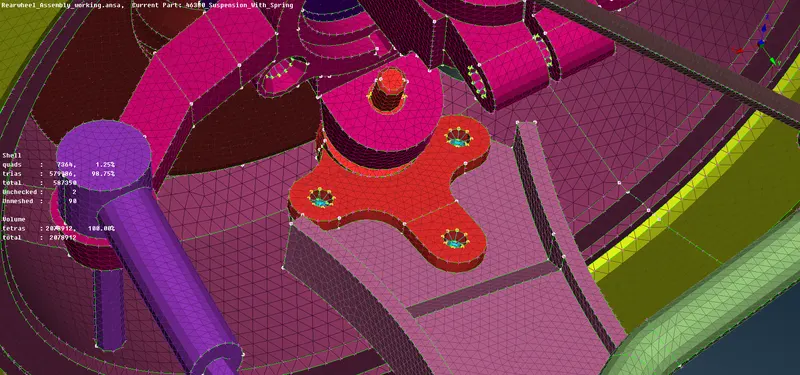
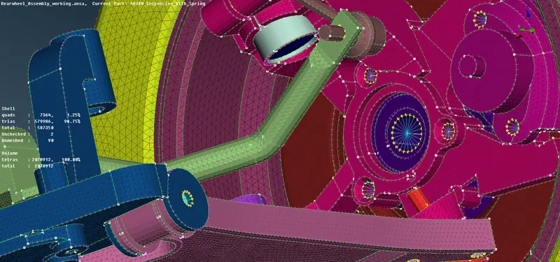
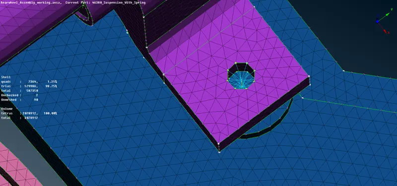
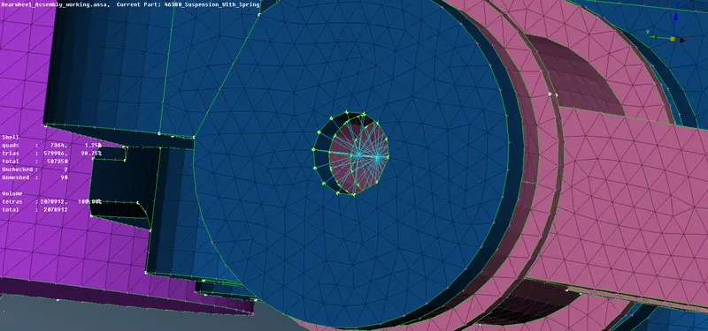
SIMILAR TYPE OF CONNECTIONS ON THE OTHER COMPONENTS THROUGHOUT THE MODEL
Create a Seam weld connection on the 2D meshed mid surfaces.
- Firstly, isolate the components where the connections has to be created.
- Click on the Feat2Curve option in the Perimeters tools in the Mesh deck.
- Convert the single con at the end of the component to a curve by selecting Feat2Curve option.
- After converting the CON to curve, convert the curve to the seam line.
- Select the Convert option in the Assembly tools which is present at the top of the window to convert the curve to Seam line.
- Select the convert option and select the seam line from the list of commands available.
- Select the curve and click enter on the keyboard in the popup window select the seam line and click Ok.
- Click on the connection manager in the assembly tools present at the top of the window and select the converted seam line and press the enter on the keyboard to confirm.
- After pressing the enter button, the connection manager window will be popped up in that select the Overlap shell joint option from the list of the options available in the FE Rep type & enter the proper value in the search distance option.
- Enter the width as 3 and enter the step length as 2 and change the bast sheet from P1 to P2 and in the root shells change it to double row and in the distribution change it to uniform and in the create a Weld ID by pressing Shift+? in the keyboard.
- After this, select the components in the P1 & P2 of where you want to create a Seam Weld connection.
- Click on the P1 and press Right-click in that and press the F1 function key on the keyboard and select the component and click Ok.
- In the same way, select the P2 for the components and click Ok.
- After selecting all the components and entering the values in the specified areas click on the apply button and then click on the Realize button the Seam weld connection is realized and can be seen on the selected components.
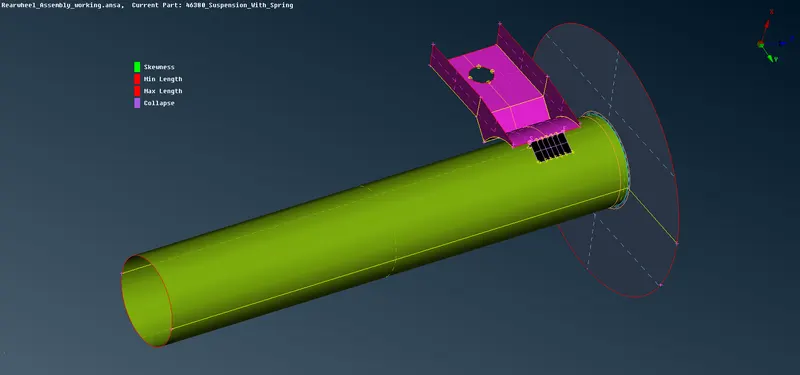
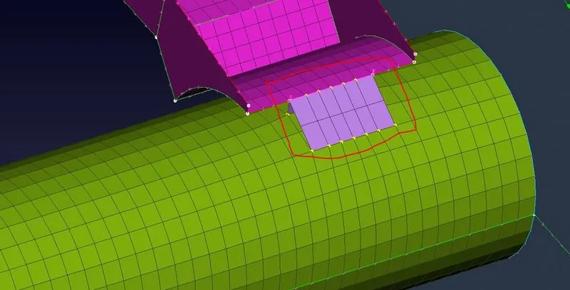
THE SEAM WELD CONNECTION IS CREATED BETWEEN TWO COMPONENTS
After establishing all the connections, mirror the same component to the other side by using the symmetry option in the Transform tool:
Click on the Transform --> Copy --> Symmetry --> select the Default Symmetry plane --> select the entities that are needed to be copied. A window will be popped up and click on the Apply option and click on the Finish option to confirm the procedure, the entities are mirrored to the other side.
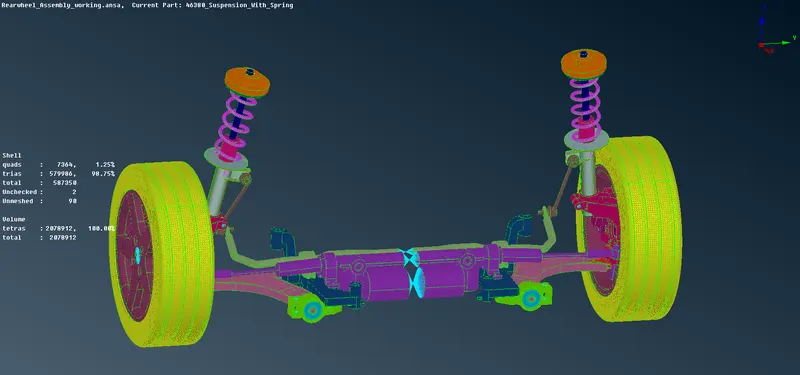
THE REARWHEEL SUSPENSION ASSEMBLY MODEL AFTER SYMMETRY PROCEDURE
Conclusion:
For the given assembly, the geometrical errors has been checked and with the given element Quality criteria the surfaces has been meshed with the trias and ortho trias. After meshing the component the thickness has to be assigned for mid surfaces with 2D elements. The tetra elements has been generated on the non-uniform thickness components. Also, appropriate connections has been made to connect different components. The symmetry procedure is performed on the model to mirror the model onto the other side.