Project 2 - Measuring the distance of an object using ultrasonic sensor and also smoothen the sensor data using moving average filter
Overview of the Project:
In this project the implementation of code for “Measuring distance of an object using ultrasonic distance sensor (28015 Ping) and also smoothen the sensor data using moving average filter”.
Goals:
Measuring the distance in terms of inches of an object using Ultrasonic Distance Sensor (28015 Ping).
The sensor data is smoothened by using Moving average filter technique to eliminate the high frequency variations from the sensor data.
Key Highlights of the Project:
Measuring the distance travelled by the wave to the object and gets bounced back from the object to sensor.
Smoothening the sensor data by moving average filter technique, the filter has a window of certain size. That window determines that how many data the filter can take.
Deliverables of this project:
The distance travelled by a wave to the object for which we want to measure the distance using Ultrasonic Distance Sensor (28015 Ping).
Eliminate the high frequency jitters from the sensor data by Moving Average filter to smoothen the sensor data.
Expected Outcomes:
The students will get the Knowledge on Ultrasonic sensor (28015 Ping) to measure the distance travelled by wave to the object, the hardware connection of 2 Arduino’s connected to the sensor and smoothening the sensor data by removing high frequency variations using Moving Average Filter Technique.
THEORY:
1) Ultrasound is a high-pitched sound wave whose frequency exceeds the audible range of human hearing.
HC sensor: Operating voltage: 5V
HC ultrasonic distance sensor actually consists of two ultrasonic transducers.
First transducer converts electrical energy into sound energy of very high frequency (ultrasonic waves) this is transmitter.
Second transducer converts reflected sound energy into electrical energy, this is reciever.
The receiver produces the output electrial PWM waves whose duty cycle is proportional to the distance of reflection.
Sensor produces highly accurate output with deviation of 3 to 4mm from the actual position of object.
WORKING:
The above mentioned sensor have 4 pins, TRIG, EN, GND, VCC.
When the TRIG pin is set HIGH. In response, the sensor transmits an ultrasonic burst of eight pulses at 40 kHz.
These eight ultrasonic pulses travel through the air away from the transmitter.
After the transmissin the ECHO is pin is turned on to receive signal.
If those pulses are not reflected back, the echo signal times out and goes low after 38ms. Thus a pulse of 38ms indicates no obstruction within the range of the sensor.
If those pulses are reflected back, the echo pin goes low as soon as the signal is received. This generates a pulse on the echo pin whose width varies from 150 µs to 25 ms depending on the time taken to receive the signal.
MEASURING DISTANCE:
The PWM wavesare generated by receiver as output.
The duty cycle or width of signal is directly prportional to the distance travelled by the wave.
Now let’s calculate how far the object is from the sensor. For this we will use the below equation.
Distance = Speed x Time
2) Arduino:
Arduino is electronic platform used to make projects, prototypes, etc.
The platform contains ATmega328 micro controller on board with ADC, 14 I/O digital pins, 6 analog pins.
Arduino is an open-source electronics platform based on easy-to-use hardware and software.
Different inputs to arduino can include - light sensor, a button - and turn it into an output, a motor, a LED. You can tell your board what to do by sending a set of instructions to the Arduino board.
PROGRAM:
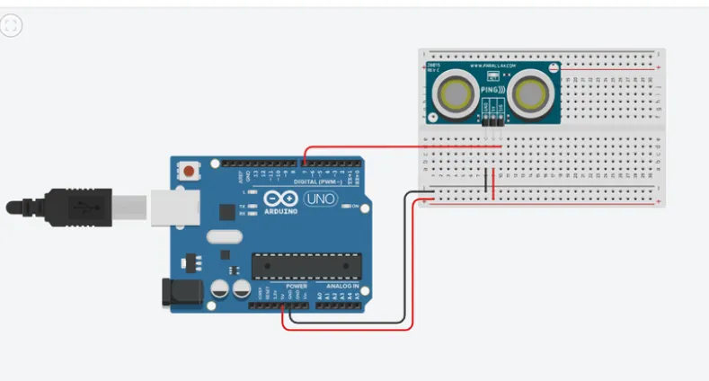
/* CIR DIA:
1) VCC-> 5V (+VE)
2) GND-> GROUND (-VE)
3) SIG-> PIN NO 07
*/
const int pingPin = 7; /*VARIABLE DECLARED*/
void setup() /*DECLARE VARIABLES, FUNC, ETC*/
{
/*INITIALIZATION-> SERIAL COMMU*/
Serial.begin(9600);
}
void loop() /*LOOP FUNC*/
{
long duration, inches, cm; /*DECLARE VARIABLES FOR TIME, DISTANCE*/
pinMode(pingPin, OUTPUT); /*PINMODE OF PINGPIN-> OUTPUT*/
digitalWrite(pingPin, LOW); /*PINGPIN-> LOW*/
delayMicroseconds(2); /*DELAY*/
digitalWrite(pingPin, HIGH); /*PINGPIN-> HIGH*/
delayMicroseconds(5); /*DELAY*/
digitalWrite(pingPin, LOW); /*PINGPIN-> LOW*/
/* The same pin is used to read the signal from the PING))): a HIGH pulse
whose duration is the time (in microseconds) from the sending of the ping
to the reception of its echo off of an object.*/
pinMode(pingPin, INPUT);
duration = pulseIn(pingPin, HIGH);
/*TIME = DISTANCE / SPEED*/
inches = microsecondsToInches(duration);
cm = microsecondsToCentimeters(duration);
Serial.print(inches); /*PRINT*/
Serial.print("in, "); /*PRINT*/
Serial.print(cm); /*PRINT*/
Serial.print("cm"); /*PRINT*/
Serial.println(); /*PRINT*/
delay(100);
}
long microsecondsToInches(long microseconds)
{
return microseconds / 74 / 2; /*DIST INCH = MICRO SEC / 74 / 2*/
}
long microsecondsToCentimeters(long microseconds) {
return microseconds / 29 / 2; /*DIST CM = MICRO SEC / 29 / 2*/
}
CIRCUIT DIAGRAM:
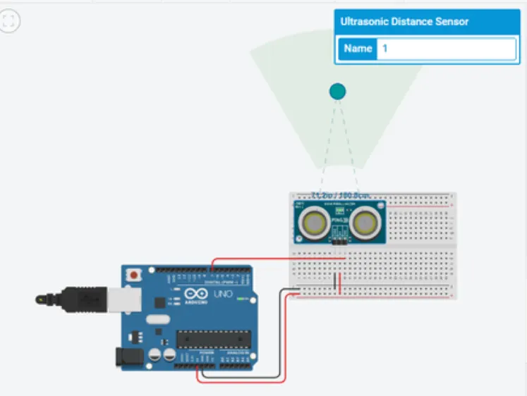
OUTPUT:

CONCLUSION
We studied and built required program and also observed output.