Project
REPORT MODULE01
TASK01
AIM
Carry out a system-level simulation of an all-terrain vehicle (ATV).
OBJECTIVES
1) To download the ATV model from the given link.
2) To carry out a system-level simulation of an all-terrain vehicle.
3) To prepare a technical report explaining the model properties & comments on the results.
THEORY
All-Terrain Vehicle (ATV):
1) An all-terrain vehicle (ATV) is defined as a motorized off-highway vehicle designed to travel on four low-pressure or non-pneumatic tires, having a seat and handlebars for steering control.
2) ATV means all-terrain vehicle which is specially designed for off roads driving. ATV is designed for very rough terrain, jumps, flexibility and endurance.
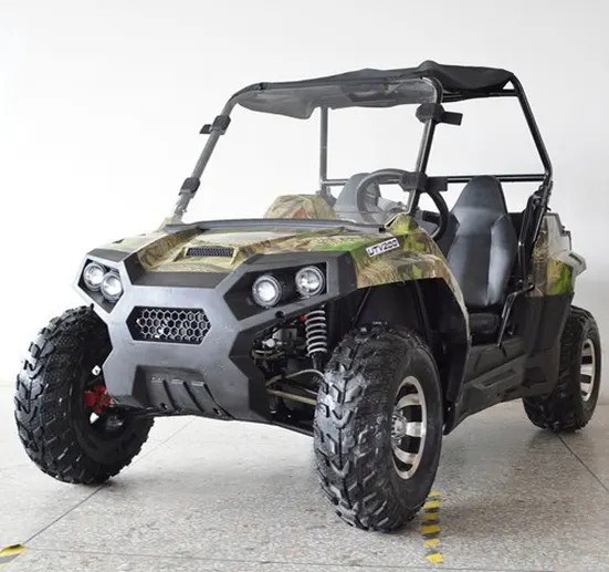
FIG: All-terrain vehicle
Main Components:
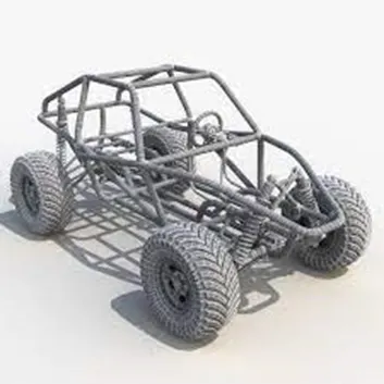
1) Chassis:
- Chassis is the vehicle’s main support structure, also known as the ‘Frame.’ It bears all the stresses on the vehicle in both static and dynamic conditions.
- Frame also provides structure to connect all other parts like engine, suspension system, tyres, braking system etc.
- In ATV, we generally use ‘Roll Cage’ which protects person in case of roll over.
2) Suspension System:
- In ATV we use Independent Suspension System.
- Independent suspension system allows each wheel on the same axle to move vertically independently of the others.
- Suspension system is system that connects wheels to the vehicle body. It consists of springs, linkages, joints.
- It protects body of vehicle from direct shock and damage.

3) Engine:
- There are two types of engines available, two stroke and four stroke.
- Power is transmitted from engine to axle through chain or differential.
- Engines develop power around 5 to 20 HP. They run around 11000 rpm.
4) Engine Mounting:
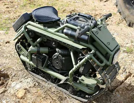
- Sometimes the length of chain connecting engine to the axle may change due to temperature, dragging of chain, due to external factors, etc.
- In such condition it is required to move the position of the engine to compensate such a change.
- Hence Engine is mounted on the tray which can move. That tray is known as Engine Mounting.
5) Transmission System:
Axle:
- A live axle on ATV means that the engine will power both rear wheels at the same speed and power.
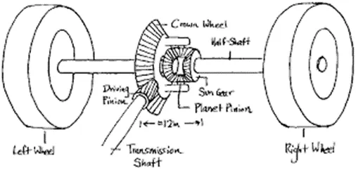
Automotive Differential:
- The automotive differential is designed to drive a pair of wheels while allowing them to rotate at different speeds. In vehicles without a differential, such as karts, both driving wheels are forced to rotate at the same speed.
Tyres:
- Tyres of ATV are designed for rough surfaces and for different road conditions like dry or wet.
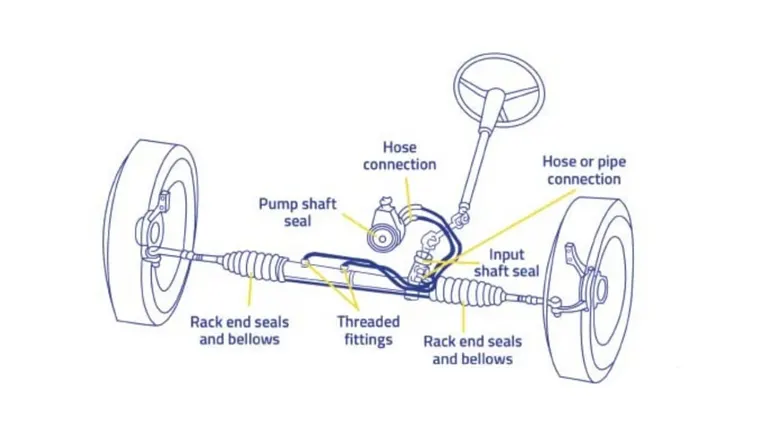
Steering System:
- The purpose of Steering system is to give direction to the vehicle.
- It should be rigid to withstand the stress on the wheels.
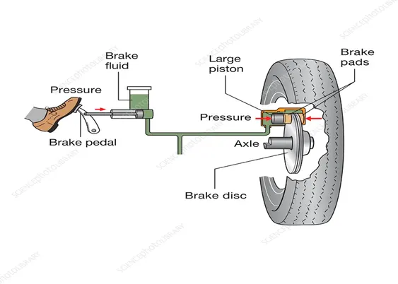
Brake System:
- Brakes are used to slow down or stop the vehicle.
- Hydraulic Brake system is mainly used in the ATV.
- When person pushes the brake paddle, a piston is connected to the paddle will exert force on the oil in cylinder.
- Tubes are connected from oil cylinder to brake pads. So, when piston apply force on the oil it is transferred to the brake pads and friction between brake disc and brake pads will slow down vehicle.
BODY
Model:
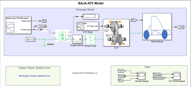
FIG: BAJA ATV MODEL
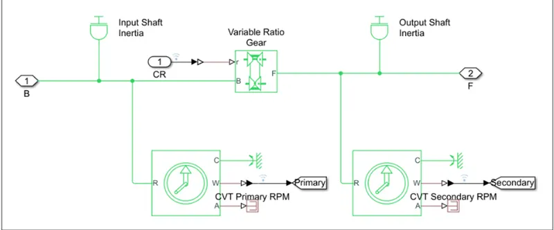
CVT MODEL:
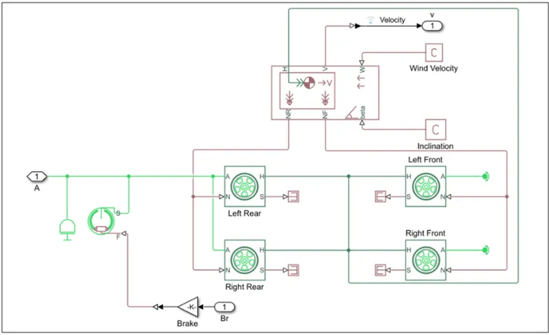
VEHICLE BODY:
Blocks Used:
Signal Builder, Go TO, From, Generic Engine, Engine sensor, Simple Gear, Display, CVT, Vehicle Body, Scope, Inertia, Variable gear ratio, Rotational Reference, PS-Simulink Converter, Rotational Motion Sensor, Solver Configuration, Constant, Lookup Table, Step.
Logic:
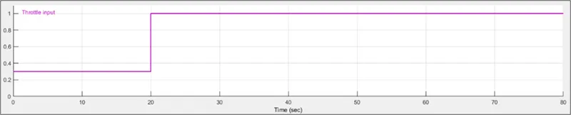
1) We give input of Brake and throttle through Signal Builder to Engine block.
2) Output of engine is given to the Engine Sensor to measure speed and then to Simple gear to reduce speed obtained from engine’
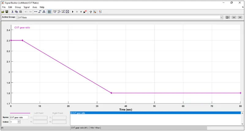
3) Output of CVT block is given to the Vehicle Body. CVT Ratio build with signal builder is given as input to the CVT block
4) We use GOTO and from blocks to measure values of Brake, Throttle, Speed and give as inputs to the Scopes.
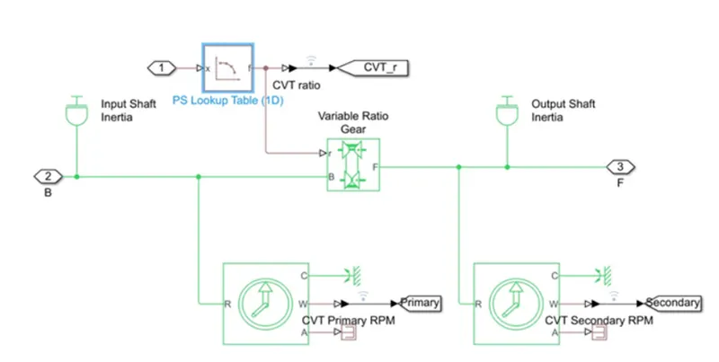
5) Inside the CVT block, we have variable gear ratio as shown in CVT model. We used Rotational motion sensor to measure speeds of primary and secondary gears of CVT.
6) Inside Vehicle Body block, we modelled Brake system, Tyres, Wind Velocity, Inclination, Velocity. We measure output velocity by combining all these effects.
The Brake input:

Throttle input is given below:
CVT Gear Ratio input:
OUTPUT
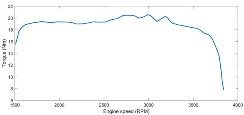
1) Speed Torque Plot:
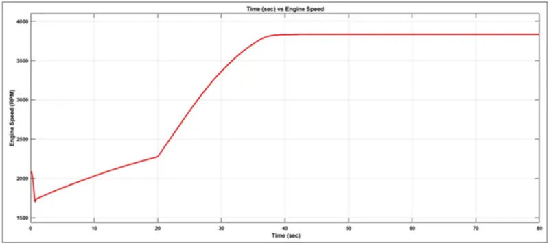
2) Engine Speed Vs Time Plot:
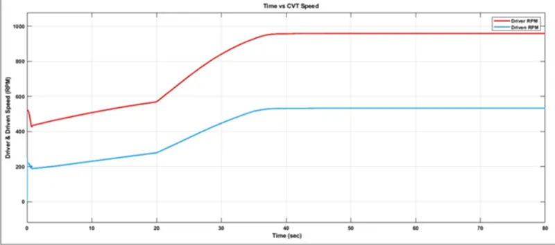
3) CVT Reduction Ratio Vs Speed:
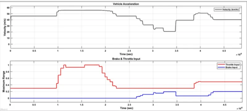
4) IP Vs OP plot:
OBSERVATIONS:
1) For different values of Brake and Throttle inputs we can change in the velocity of the vehicle.
2) We put Simple gear ratio= 4 to obtain above results.
3) As the CVT input ratio changes, output velocity also changes.
MODIFIED ATV MODEL
Model:
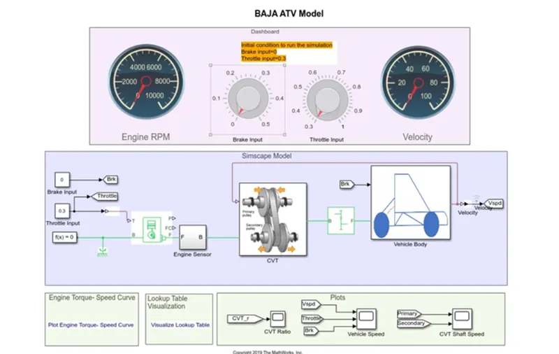
1) ATV Model with dashboard:
2) Modified CVT Model:
Logic:
1) Block Connections are identical to the previous model only changes are
- We given Broke input as Constant=0 and Throttle input as Constant=0.3.
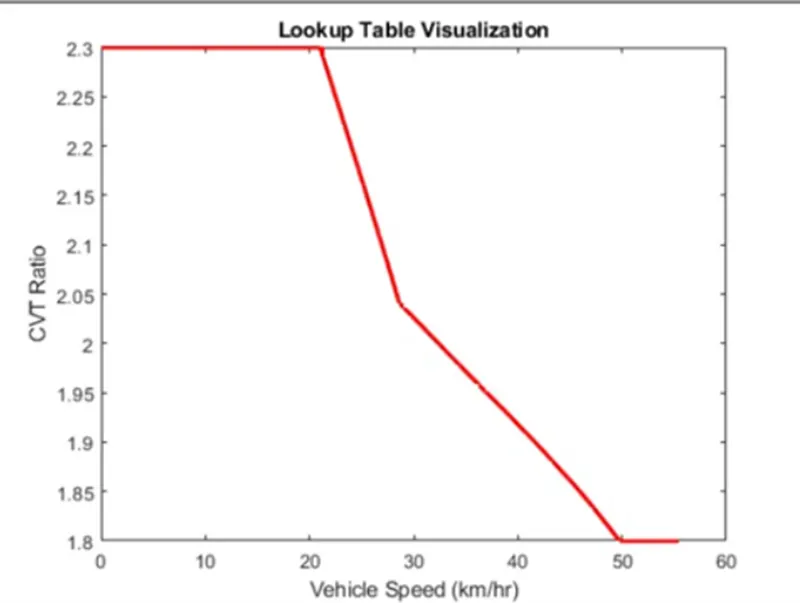
- We replaced CVT Gear ratio by Feedback from output velocity of vehicle.
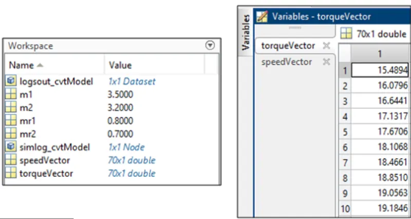
2) In CVT we used Lookup Table. Input is as below,
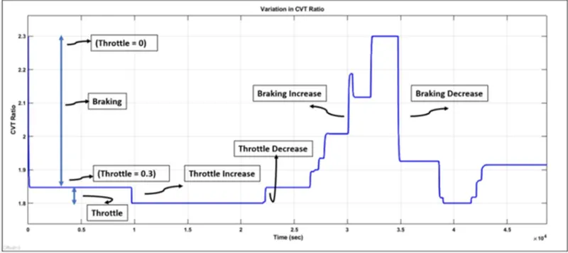
3) CVT Ratio input:
OUTPUT
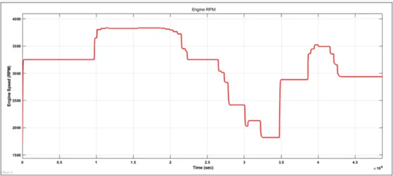
1) Speed Vs Time Plot:
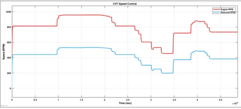
2) Speed Vs CVT Rato Plot:
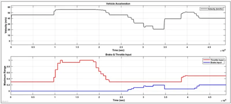
3) IP Vs OP Plot:
OBSERVATIONS:
1) In modified version we used Velocity Feedback to control output velocity.
2) We plotted graphs as before.
CONCLUSION:
We studied the BAJA ATV model and observed plots for different values of inputs and completed required objectives.