Week -2
REPORT WEEK2
TASK1
AIM
Make a Simulink Model of Doorbell using solenoid block.
OBJECTIVES
To make Simulink Model of Doorbell using solenoid block.
Create a situation where switch is closed for 2 seconds and also observe movement of plunger.
THEROY
Structure of Doorbell:

FIG: Doorbell
In above figure alphabets represent:
B- Bong
A- Plunger
E- Electromagnet
T- Contact
K- Switch
U- Battery
Working of Doorbell:
- In above figure the current direction is UKET which completes the circuit due to which electromagnet E is activated which attracts the plunger A towards E.
- Due to attraction plunger A is struck on bong B which produces the sound. The plunger is made of magnetic materials like iron which is attracted by the electromagnet.
- Contact at T is such that when A is attracted towards E the contact at T Is broken and circuit is broken. Current through circuit becomes zero which deactivates the electro magnet E and force on plunger becomes zero.
- Then plunger A returns to the original position and circuit is closed and whole process is repeated again.
Solenoid:
1) A solenoid is an electromagnetic actuator that converts electrical energy into mechanical action. It consists of a coiled wire tightly wrapped around an iron core, and a ferromagnetic plug or plunger. As an electrical current passes through the coil, a magnetic field is generated.
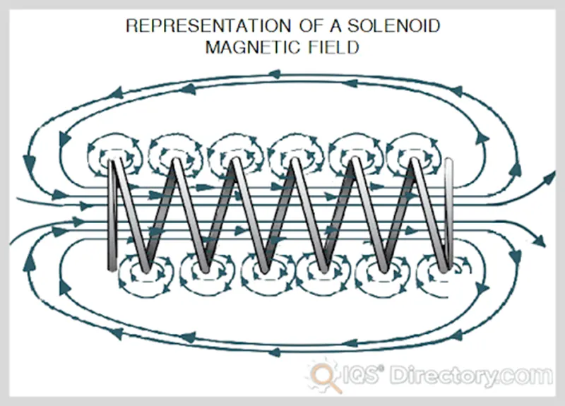
FIG: Solenoid
2) The magnetic field around the coil causes the ferromagnetic plunger to be attracted.
BODY
Model:
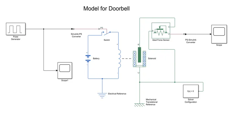
FIG: Simulink Model
Blocks Used:
Pulse Generator, Scope, Simulink-PS Converter, Switch, Battery, Electrical reference, Solenoid, Mechanical reference, Ideal Force Sensor, PS-Simulink Converter, Solver Configuration.
Logic:
1) First Solenoid block is taken. Battery is connected to power the circuit. Switch is provided to make or break the circuit.
2) To operate switch, we require external pulse generator. But we cannot connect pulse generator to the switch so we used Simulink to PS converter. Scope1 is used to observe input to switch.
3) The coil part of solenoid is connected to fixed support / mechanical reference. The moving part of solenoid (plunger) is connected to ideal force sensor. Plunger will hit bong of doorbell and produce sound. But we have to only observe movement of plunger so we connect force sensor.
4) We connect output of ideal force sensor to PS to Simulink converter and give it to Scope to observe output of Solenoid.
5) The required condition (2sec switch closed) is obtained by adjusting Time Period and Duty Cycle of Square wave from Pulse Generator.
OUTPUT
Below is output of Solenoid analysed on Scope.
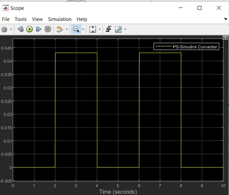
FIG: Output of Scope
OBSERVATIONS
1) From above graph we can see that:
- X-axis represent Time in Seconds
- Y-axis represent Signal proportional to Displacement of Plunger.
2) Zero on Y-axis represent plunger away from bong and 0.045 represents instant when plunger hit bong.
CONCLUSION
We made Doorbell Model using Solenoid Block and observed the output movement of Solenoid.
TASK2
AIM
To use a thermistor to sense the temperature of the heater and turn ON or turn OFF the fan as per the conditions given.
OBJECTIVES
To sense temperature of heater and turn ON fan if temperature is above 25 Degree Celsius and OFF otherwise.
THEORY
Thermistor Structure and Working:
1) A thermistor is a resistance thermometer, or a resistor whose resistance is dependent on temperature. The term is a combination of thermal and resistor. It is made of metallic oxides, pressed into a disk, or cylindrical shape and then encapsulated with an impermeable material such as epoxy or glass.
2) There are two types of thermistors: Negative Temperature Coefficient (NTC) and Positive Temperature Coefficient (PTC).
3) With an NTC thermistor, when the temperature increases, resistance decreases. Conversely, when temperature decreases, resistance increases. This type of thermistor is used the most.
4) A PTC thermistor works a little differently. When temperature increases, the resistance increases, and when temperature decreases, resistance decreases.
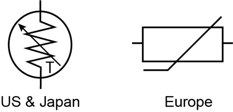
FIG: Symbol of Thermistor
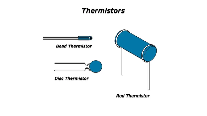
FIG: Types of Thermistors
BODY
Model:
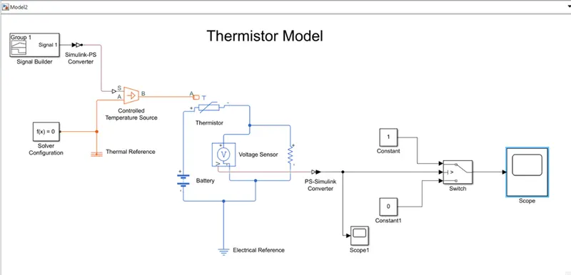
FIG: Thermistor Model
Blocks Used: Signal Builder, Simulink-PS Converter, Solver Configuration, Controlled Temperature Source, Thermistor, Battery, Voltage Sensor, Resistor, Electrical and Thermal References, PS-Simulink Converter, Scopes, Constants, Switch.
Logic:
1) We first taken Thermistor block and supply is provided with the help of Battery. In same circuit we connected Voltage Sensor across a resistor. Thermistor is basically a resistor whose value varies with the variation in the temperature.
2) When voltage drop across the thermistor changes, then voltage drop across resistor also changes and we will be able to sense the temperature change.
3) For Controlled temperature source we taken input (at Port S) of required conditions from Signal Builder through Simulink-PS Converter. The output port (Port B) is connected to input (Port T) of Thermistor. Port A is given to thermal reference.
4) Signal generated by Signal Builder is given below
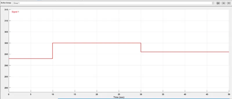
The Temperatures are converted into Kelvin and required conditions are generated.
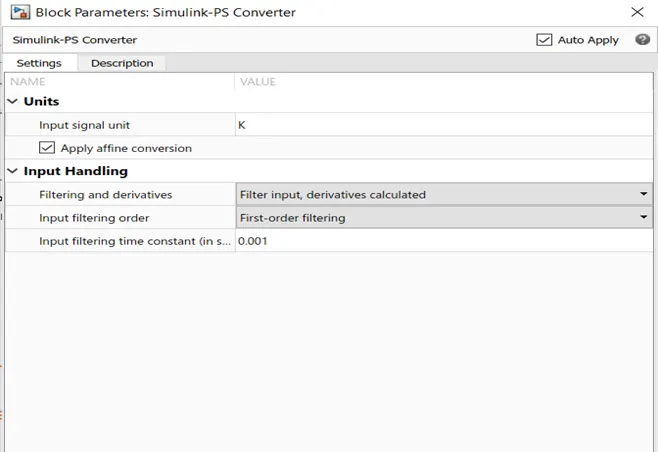
5) Parameters of Simulink-PS Converter are modified.
6) Output of Voltage Sensor is connected to the middle port of Switch through PS-Simulink Converter. Other two inputs of Switch are Constants 0 and 1 which will be output of Switch based on input conditions.
7) Parameters of Switch are:
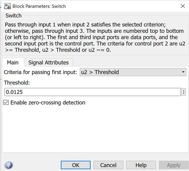
If, input is greater than threshold (0.0125), output will be 1 and 0 otherwise.
8) Output of PS-Simulink is given to Scope1 and output of Switch is given to Scope.
OUTPUT
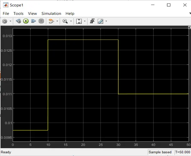
1) Output of PS-Simulink:
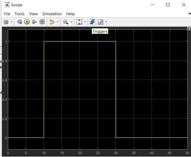
2) Output of Switch:
OBSERVATIONS
1) From above graph we can see that input to the Switch varies as required.
2) Our codition is that if Switch should be ON if temperature is above 25 degree celcius and OFF otherwise. Then Switch should be:
- OFF for 20 degree celcius (0-10 seconds).
- ON for 27 degree celcius (10-30 seconds).
- OFF for 23 degree celcius (30-50 seconds).
Switch output is:
1= ON
0= OFF
We can see from graph that conditions are fullfilled.
Switch can be connected to input of fan to control Fan.
CONCLUSION
We used Thermistor to sense temperature and ON and OFF fan as required and observed the output.