Project 2-Highway Assistant-Lane Changing Assistant
Aim:
Model Development of a Highway Assistant – Lane Changing Assistant using MATLAB Simulink with Model-Based Development guidelines like (MAAB) and producing Model Advisor Report and also generating Code using Autosar Coder
Objective:
- This model must be developed in MATLAB Simulink per MBD guidelines.
- Code Generation Profile must be Autosar Coder.
- Simulink Data Dictionary must be created for the model & must be linked to the model.
- All the input & output signals must be mapped into the Autosar Editor.
- Model Advisor Report is mandatory & this will be followed by Code Generation.
Highway Assistant – Lane Changing Assistant
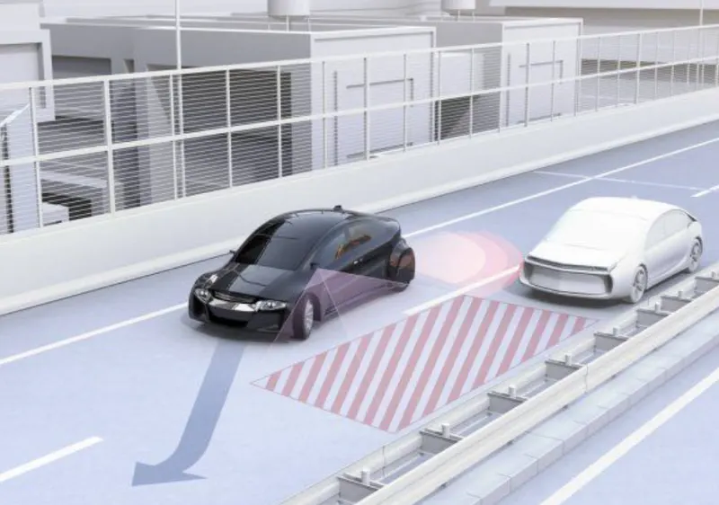
The lane-change assistant, like the lane-departure warning system, is part of the lane-assist system family. The lane-departure warning system uses a front camera, whilst the lane-change assistant uses a radar sensor at the back of the car. The system is based on two radar sensors at the vehicle's rear end that continually scan the areas beside and diagonally behind the vehicle.
If the system identifies cars in the driver's blind spot or vehicles coming quickly from behind, it alerts the driver with an illuminated sign, such as one in the region of the wing mirrors.When the driver activates the turn signal indicator to change lanes, the system can also offer an audio and/or haptic warning to draw the driver's attention to the situation.
In monotonous highway driving scenarios, the Highway Assistant assists the driver by taking over longitudinal and lateral vehicle guidance. To a certain extent, the partially automated function can start, accelerate, brake, and steer the vehicle. The driver must constantly monitor the system and be prepared to take entire control of the vehicle at any time. Drivers are instructed to check their rearview and side mirrors, as well as look over each shoulder, before changing lanes. Even for those who adhere to this checklist, the car's blind spot - the region beside and immediately behind the vehicle – is a persistent source of hazard and is frequently the cause of major accidents. Vehicles approaching swiftly from behind can also be dangerous. This functionality was created to make changing lanes safer.
Highway Assistant is a semi-automated driving option for highway speeds of up to 180 km/h (112 mph). It combines Adaptive Cruise Control (ACC radar-based )'s longitudinal guiding with lane-keeping support's video-based lateral guidance in a single system. Highway Assistant can be enhanced by a driver-initiated and monitored automatic lane change at speeds ranging from 60 to 130 km/h (35 to 80 mph).
The Lane Change Assistant works by concealing two mid-range radar sensors in the rear bumper — one on the left and one on the right. These two sensors keep an eye on the area beside and behind the vehicle. The sensor data is combined by powerful control software to produce a full picture of all traffic in the region behind the vehicle. When another vehicle approaches from behind at high speed or is already in the driver's blind zone, a signal such as a warning light in the side mirror informs the driver of the threat. If the motorist continues to use the turn signal with the aim of changing lanes, the system will send additional audio and/or haptic warning.
Input Signals:
|
Name of the Signal |
Data Type |
Range |
|
Highway_Input_Signal |
uint8 |
0 - 255 |
|
Enable_Display |
uint8 |
0 – 255 |
|
Input_Switch |
uint8 |
0 – 255 |
|
Lane_Input_Signal |
uint8 |
0 - 255 |
Local Signals:
|
Name of the Signal |
Data Type |
Range |
|
Highway_Display_Mode_1 |
uint8 |
0 - 255 |
|
Highway_Display_Mode_2 |
uint8 |
0 – 255 |
|
Highway_Display_Mode_3 |
uint8 |
0 – 255 |
|
Highway_Display_Mode_4 |
uint8 |
0 – 255 |
|
Lane_Display_Mode_1 |
uint8 |
0 – 255 |
|
Lane_Display_Mode_2 |
uint8 |
0 – 255 |
|
Lane_Display_Mode_3 |
uint8 |
0 – 255 |
|
Lane_Display_Mode_4 |
uint8 |
0 – 255 |
Output Signals:
|
Name of the Signal |
Data Type |
Range |
|
Display_Mode_1 |
uint8 |
0 - 255 |
|
Display_Mode_2 |
uint8 |
0 – 255 |
|
Display_Mode_3 |
uint8 |
0 – 255 |
|
Display_Mode_4 |
uint8 |
0 - 255 |
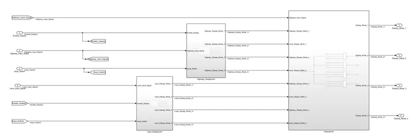
Requirement No 1 [Highway_DisplayUnit]:
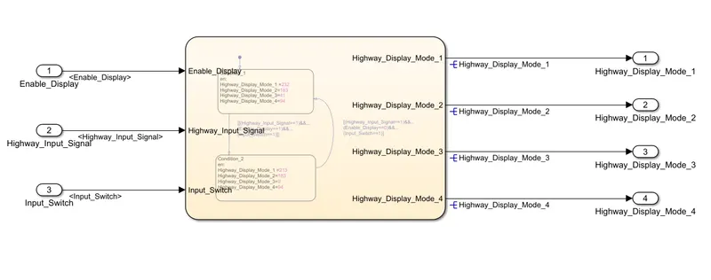
Inputs to this particular subsystem are “Highway_Input_Signal”, “Enable_Display”, “Input_Switch”. These three input signals, when assigned to a particular value will give output signals of specific value. The output signals are “Highway_Display_Mode_1”, “Highway_Display_Mode_2”, “Highway_Display_Mode_3”, “Highway_Display_Mode_4”. The requirement must be implemented in the form of a Stateflow logic.
|
Condition |
Action |
|
Highway_Input_Signal = 1 Enable_Display = off Input_Switch = on |
Highway_Display_Mode_1 = 232 Highway_Display_Mode_2 = 183 Highway_Display_Mode_3 = 41 Highway_Display_Mode_4 = 94 |
|
Highway_Input_Signal = 1 Enable_Display = on Input_Switch = on |
Highway_Display_Mode_1 = 213 Highway_Display_Mode_2 = 183 Highway_Display_Mode_3 = 9 Highway_Display_Mode_4 = 94 |
Requirement No 2 [Lane_DisplayUnit]:
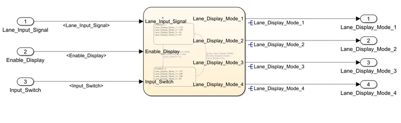
Inputs to this particular subsystem are “Enable_Display”, “Input_Switch”, “Lane_Input_Signal”. These three input signals, when assigned to a particular value will give output signals of specific value. The output signals are “Lane_Display_Mode_1”, “Lane_Display_Mode_2”, “Lane_Display_Mode_3”, “Lane_Display_Mode_4”. The requirement must be implemented in the form of Stateflow logic.
|
Condition |
Action |
|
Lane_Input_Signal= 6 Enable_Display = off Input_Switch = on |
Lane_Display_Mode_1 = 132 Lane_Display_Mode_2 = 185 Lane_Display_Mode_3 = 54 Lane_Display_Mode_4 = 67 |
|
Lane_Input_Signal= 6 Enable_Display = on Input_Switch = on |
Lane_Display_Mode_1 = 127 Lane_Display_Mode_2 = 248 Lane_Display_Mode_3 = 186 Lane_Display_Mode_4 = 84 |
Requirement No 3:
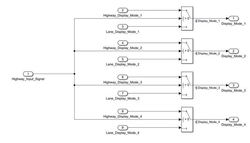
Signals coming from both subsystems “Highway_Display_Mode_1” & “Lane_Display_Mode_1” are given as inputs to a switch block which will have input signal “Highway_Input_Signal” given as 2nd input to the switch block. Corresponding output from this particular switch block is output signal “Display_Mode_1”.
Signals coming from both subsystems “Highway_Display_Mode_2” & “Lane_Display_Mode_2” are given as inputs to a switch block which will have input signal “Highway_Input_Signal” given as 2nd input to the switch block. Corresponding output from this particular switch block is output signal “Display_Mode_2”.
Signals coming from both subsystems “Highway_Display_Mode_3” & “Lane_Display_Mode_3” are given as inputs to a switch block which will have input signal “Highway_Input_Signal” given as 2nd input to the switch block. Corresponding output from this particular switch block is output signal “Display_Mode_3”.
Signals coming from both subsystems “Highway_Display_Mode_4” & “Lane_Display_Mode_4” are given as inputs to a switch block which will have input signal “Highway_Input_Signal” given as 2nd input to the switch block. Corresponding output from this particular switch block is output signal “Display_Mode_4”.
Highway Assistant – Lane Changing Assistant
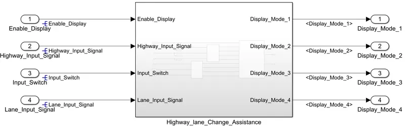
Simulink Data Dictionary(SLDD): MathWorks introduced a new feature in 2014 that is called Simulink Data Dictionary. This new feature provides the ability to save data types, parameters, and signals to database files. This is good news for embedded developers who need flexibility in using data objects and don't want to use the default workspace, which can lead to data corruption. In the initial implementation, the data dictionary interface is provided by the Simulink Model Explorer. The GUI is clean, intuitive, and easy to use. It helps in importing and exporting dictionaries to m-files and mat-files.
The Simulink data dictionary, also known as SLDD, exists as a file with the standard file extension .sldd. The dictionary file can be opened with the open function that calls opensldd. This will open the file and launch Simulink Model Explorer on the selected dictionary node. Opening the dictionary creates a cached copy. Manipulating the dictionary modifies the cached copy. The dictionary file changes only if the changes are saved with the appropriate command. You can add elements to the dictionary by creating a model, default workspace, or new element in the Model Explorer. You can pre-link a Simulink model using the Model Properties drop-down menu in the Simulink Editor. Data dictionaries allow you to customize model code generation for a variety of purposes by simply changing the dictionary you are using.
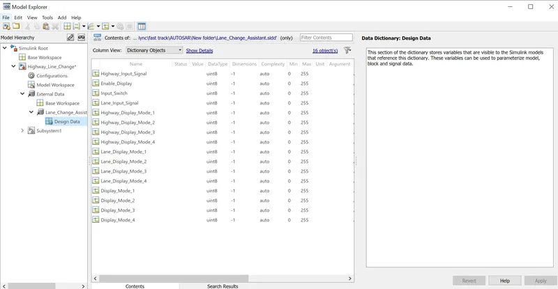
The process of making SLDD file for the model
Go to Model properties > click on the external Data>create a new file with .sldd extension> save the file
Add Simulink signal by adding input, output and local signals and using simulink parameter for adding constant data.
-give the value for maximum and minimum along with the data type if required change resolution as asked.
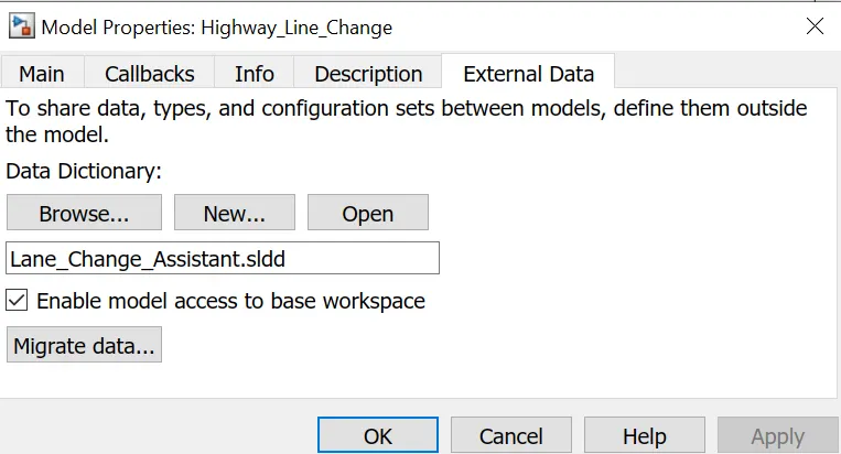
The process of linking SLDD file with the model
Go to Modeling > Model Setting > Model Properties > External Data > Browse
Model Advisor Report for MAB guidelines
The Model Advisor tests the version or subsystem to see the modeling situation and configuration settings that make the simulation of the machine that the version represents incorrect or inefficient. Model Advisor testing helps ensure compliance with business requirements and tips. Model Advisors allow initiatives and improvement teams to enable certain modeling tips. Once the version has been evaluated, the Model Advisor will create a document that lists the suboptimal situations, settings, and modeling strategies and suggests solutions as needed.
You can use the Model Advisor to test the version in the following ways:
- Model AdvisorPerform Tests Interactively Configure Model Advisor to run turnaround time tests mechanically (call Simulink ® Check ™)
Model Advisor Report for MAB guidelines
The Model Advisor tests the version or subsystem to see the modeling situation and configuration settings that make the simulation of the machine that the version represents incorrect or inefficient. Model Advisor testing helps ensure compliance with business requirements and tips. Model Advisors allow initiatives and improvement teams to enable certain modeling tips. Once the version has been evaluated, the Model Advisor will create a document that lists the suboptimal situations, settings, and modeling strategies and suggests solutions as needed.
You can use the Model Advisor to test the version in the following ways:
- Model AdvisorPerform Tests Interactively Configure Model Advisor to run turnaround time tests mechanically (call Simulink ® Check ™)
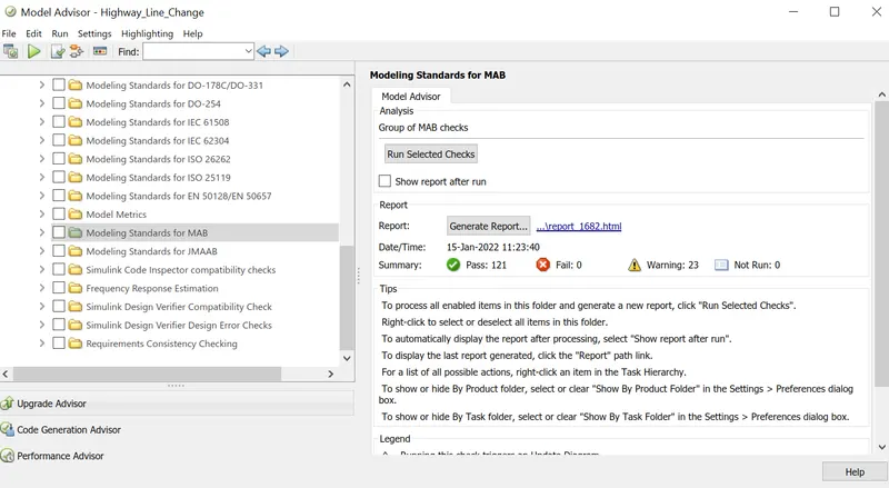
Go to task and select MAB guideline and run to get model advisor report.
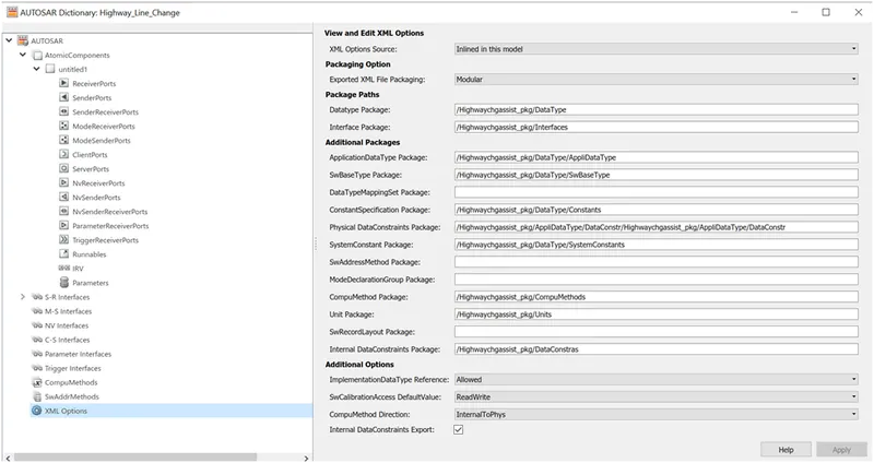
Autosar Dictionary
The AUTOSAR Dictionary and the Code Mappings editor in Simulink® can be used independently or together to graphically configure an AUTOSAR software component and map Simulink model elements to AUTOSAR component elements. See AUTOSAR Component Configuration for more details.
To configure AUTOSAR elements from an AUTOSAR perspective, use the AUTOSAR Dictionary. The AUTOSAR Dictionary displays a mapped AUTOSAR component and its elements, communication interfaces, computation methods, software address methods, and XML options in a tree structure. Select AUTOSAR elements and configure their properties using the tree. The properties you change are reflected in the exported ARXML descriptions and, in some cases, in the resulting AUTOSAR-compliant C code.
AUTOSAR Elements Configuration Workflow
In Simulink, configure the following AUTOSAR component parts for the Classic Platform:
- Open a model that has the AUTOSAR system target file autosar.tlc selected.
- Create or open an AUTOSAR model mapped view. Do one of the following in the model window:
- From the Apps tab, open the AUTOSAR Component Designer app.
- Click the perspective control in the lower-right corner and select Code.
3. Open the AUTOSAR Dictionary. Either click the AUTOSAR Dictionary button  in the Code Mappings editor or, on the AUTOSAR tab, select Code Interface > AUTOSAR Dictionary.
4. Navigate the AUTOSAR Dictionary tree to configure AUTOSAR components and properties. You can see and alter the characteristics of elements by adding them, removing them, or selecting them. Use the Filter Contents box (if available) to show specific components while hiding others in the current view.
5. Open the Code Mappings editor after defining the AUTOSAR elements and properties. Map Simulink elements to new or changed AUTOSAR elements using the Code Mapping tabs.
6. To validate the AUTOSAR component configuration, click the Validate button. If mistakes are reported, fix them before retrying validation.
XML options
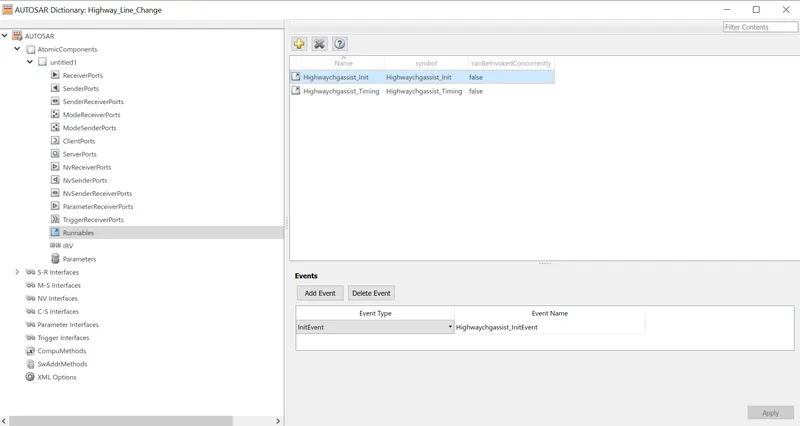
Runnable
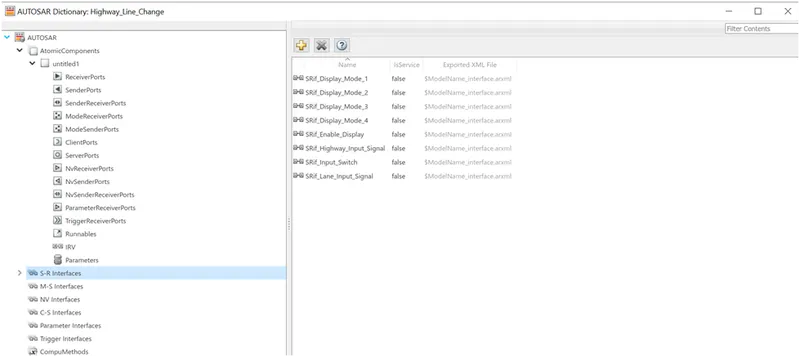
S-R Interface
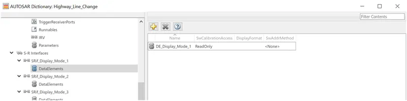
Data Element
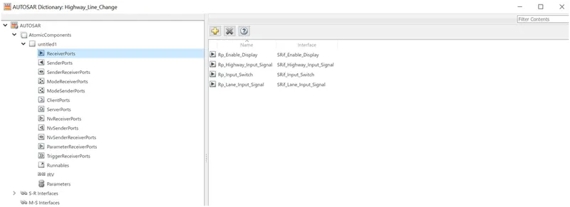
Receiver Ports
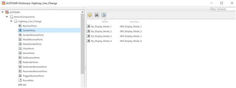
Sender Ports
Code mapping in Autosar for Inports

Code mapping in Autosar for Outports

Code mapping in Autosar for Runnable

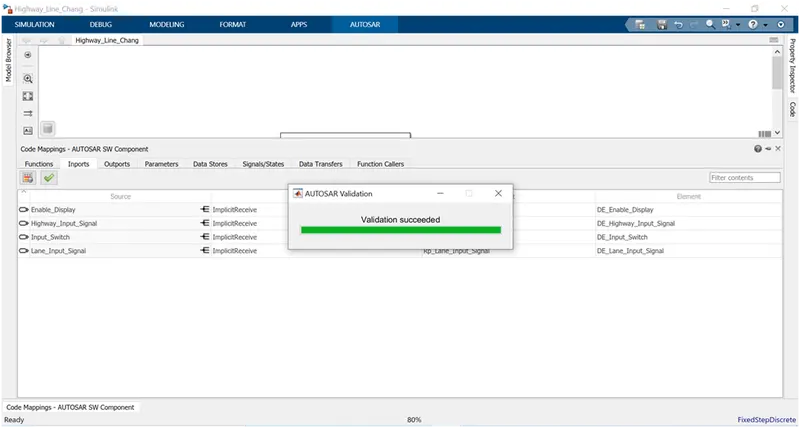
Autosar code mapping validation
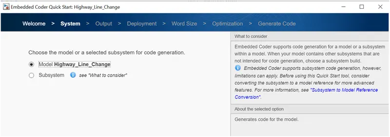
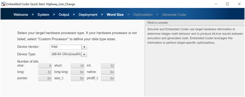
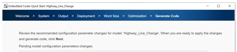
Autosar Quick Start for code generation
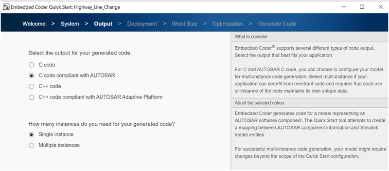
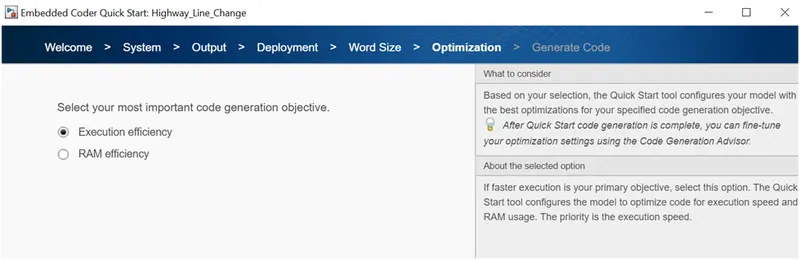
Autosar code generation
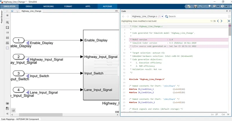
/*
 * File: Highway_Line_Change.c
 *
 * Code generated for Simulink model 'Highway_Line_Change'.
 *
 * Model version                  : 1.4
 * Simulink Coder version         : 9.5 (R2021a) 14-Nov-2020
 * C/C++ source code generated on : Sat Jan 15 10:51:11 2022
 *
 * Target selection: autosar.tlc
 * Embedded hardware selection: Intel->x86-64 (Windows64)
 * Code generation objectives:
 *    1. Execution efficiency
 *    2. RAM efficiency
 * Validation result: Not run
 */

#include "Highway_Line_Change.h"

/* Named constants for Chart: '/Chart' */
#define IN_Condition_1                 ((uint8)1U)
#define IN_Condition_2                 ((uint8)2U)

/* Named constants for Chart: '/Chart' */
#define IN_Conditioin_1                ((uint8)1U)

/* Block signals and states (default storage) */
DW rtDW;

/* Model step function */
void Highwaychgassist_Timing(void)
{
  sint32 tmp;
  uint8 rtb_Highway_Display_Mode_1;
  uint8 rtb_Highway_Display_Mode_2;
  uint8 rtb_Highway_Display_Mode_3;
  uint8 rtb_Highway_Display_Mode_4;

  /* Chart: '/Chart' incorporates:
   *  Inport: '/Enable_Display'
   *  Inport: '/Highway_Input_Signal'
   *  Inport: '/Input_Switch'
   */
  if (rtDW.is_active_c3_Highway_Line_Chang == 0U) {
    rtDW.is_active_c3_Highway_Line_Chang = 1U;
    rtDW.is_c3_Highway_Line_Change = IN_Condition_1;
    rtb_Highway_Display_Mode_1 = 232U;
    rtb_Highway_Display_Mode_3 = 41U;
  } else if (rtDW.is_c3_Highway_Line_Change == IN_Condition_1) {
    rtb_Highway_Display_Mode_1 = 232U;
    rtb_Highway_Display_Mode_3 = 41U;
    if ((Rte_IRead_Highwaychgassist_Timing_Rp_Highway_Input_Signal_DE_Highway_Input_Signal
         () == 1) &&
        (Rte_IRead_Highwaychgassist_Timing_Rp_Enable_Display_DE_Enable_Display
         () == 1) &&
        (Rte_IRead_Highwaychgassist_Timing_Rp_Input_Switch_DE_Input_Switch
         () == 1)) {
      rtDW.is_c3_Highway_Line_Change = IN_Condition_2;
      rtb_Highway_Display_Mode_1 = 213U;
      rtb_Highway_Display_Mode_3 = 9U;
    }
  } else {
    /* case IN_Condition_2: */
    rtb_Highway_Display_Mode_1 = 213U;
    rtb_Highway_Display_Mode_3 = 9U;
    if ((Rte_IRead_Highwaychgassist_Timing_Rp_Highway_Input_Signal_DE_Highway_Input_Signal
         () == 1) &&
        (Rte_IRead_Highwaychgassist_Timing_Rp_Enable_Display_DE_Enable_Display
         () == 0) &&
        (Rte_IRead_Highwaychgassist_Timing_Rp_Input_Switch_DE_Input_Switch
         () == 1)) {
      rtDW.is_c3_Highway_Line_Change = IN_Condition_1;
      rtb_Highway_Display_Mode_1 = 232U;
      rtb_Highway_Display_Mode_3 = 41U;
    }
  }

  /* End of Chart: '/Chart' */

  /* Switch: '/Switch2' incorporates:
   *  Inport: '/Highway_Input_Signal'
   *  Switch: '/Switch'
   *  Switch: '/Switch1'
   */
  tmp =
    Rte_IRead_Highwaychgassist_Timing_Rp_Highway_Input_Signal_DE_Highway_Input_Signal
    ();
  if (tmp <= 0) {
    rtb_Highway_Display_Mode_1 = 183U;
  }

  /* End of Switch: '/Switch2' */

  /* Outport: '/Display_Mode_1' */
  Rte_IWrite_Highwaychgassist_Timing_Pp_Display_Mode_1_DE_Display_Mode_1
    (rtb_Highway_Display_Mode_1);

  /* Switch: '/Switch' */
  if (tmp <= 0) {
    rtb_Highway_Display_Mode_3 = 94U;
  }

  /* Outport: '/Display_Mode_2' */
  Rte_IWrite_Highwaychgassist_Timing_Pp_Display_Mode_2_DE_Display_Mode_2
    (rtb_Highway_Display_Mode_3);

  /* Chart: '/Chart' incorporates:
   *  Inport: '/Enable_Display'
   *  Inport: '/Input_Switch'
   *  Inport: '/Lane_Input_Signal'
   */
  if (rtDW.is_active_c1_Highway_Line_Chang == 0U) {
    rtDW.is_active_c1_Highway_Line_Chang = 1U;
    rtDW.is_c1_Highway_Line_Change = IN_Conditioin_1;
    rtb_Highway_Display_Mode_1 = 132U;
    rtb_Highway_Display_Mode_2 = 185U;
    rtb_Highway_Display_Mode_3 = 54U;
    rtb_Highway_Display_Mode_4 = 67U;
  } else if (rtDW.is_c1_Highway_Line_Change == IN_Conditioin_1) {
    if ((Rte_IRead_Highwaychgassist_Timing_Rp_Lane_Input_Signal_DE_Lane_Input_Signal
         () == 6) &&
        (Rte_IRead_Highwaychgassist_Timing_Rp_Enable_Display_DE_Enable_Display
         () == 1) &&
        (Rte_IRead_Highwaychgassist_Timing_Rp_Input_Switch_DE_Input_Switch
         () == 1)) {
      rtDW.is_c1_Highway_Line_Change = IN_Condition_2;
      rtb_Highway_Display_Mode_1 = 127U;
      rtb_Highway_Display_Mode_2 = 248U;
      rtb_Highway_Display_Mode_3 = 186U;
      rtb_Highway_Display_Mode_4 = 84U;
    } else {
      rtb_Highway_Display_Mode_1 = 132U;
      rtb_Highway_Display_Mode_2 = 185U;
      rtb_Highway_Display_Mode_3 = 54U;
      rtb_Highway_Display_Mode_4 = 67U;
    }

    /* case IN_Condition_2: */
  } else if
      ((Rte_IRead_Highwaychgassist_Timing_Rp_Lane_Input_Signal_DE_Lane_Input_Signal
        () == 6) &&
       (Rte_IRead_Highwaychgassist_Timing_Rp_Enable_Display_DE_Enable_Display
        () == 0) &&
       (Rte_IRead_Highwaychgassist_Timing_Rp_Input_Switch_DE_Input_Switch
        () == 1)) {
    rtDW.is_c1_Highway_Line_Change = IN_Conditioin_1;
    rtb_Highway_Display_Mode_1 = 132U;
    rtb_Highway_Display_Mode_2 = 185U;
    rtb_Highway_Display_Mode_3 = 54U;
    rtb_Highway_Display_Mode_4 = 67U;
  } else {
    rtb_Highway_Display_Mode_1 = 127U;
    rtb_Highway_Display_Mode_2 = 248U;
    rtb_Highway_Display_Mode_3 = 186U;
    rtb_Highway_Display_Mode_4 = 84U;
  }

  /* End of Chart: '/Chart' */

  /* Switch: '/Switch1' incorporates:
   *  Switch: '/Switch3'
   */
  if (tmp > 0) {
    /* Outport: '/Display_Mode_3' */
    Rte_IWrite_Highwaychgassist_Timing_Pp_Display_Mode_3_DE_Display_Mode_3
      (rtb_Highway_Display_Mode_1);

    /* Outport: '/Display_Mode_4' */
    Rte_IWrite_Highwaychgassist_Timing_Pp_Display_Mode_4_DE_Display_Mode_4
      (rtb_Highway_Display_Mode_3);
  } else {
    /* Outport: '/Display_Mode_3' */
    Rte_IWrite_Highwaychgassist_Timing_Pp_Display_Mode_3_DE_Display_Mode_3
      (rtb_Highway_Display_Mode_2);

    /* Outport: '/Display_Mode_4' */
    Rte_IWrite_Highwaychgassist_Timing_Pp_Display_Mode_4_DE_Display_Mode_4
      (rtb_Highway_Display_Mode_4);
  }
}

/* Model initialize function */
void Highwaychgassist_Init(void)
{
  /* (no initialization code required) */
}

/*
 * File trailer for generated code.
 *
 * [EOF]
 */
Result:The model that is created in Matlab Simulink for Highway Assistant – Lane Changing Assistant is converted by using Autosar dictionary and code mapping and running the quick start to get Codde for the model this code is Autosar Embedded code for the model