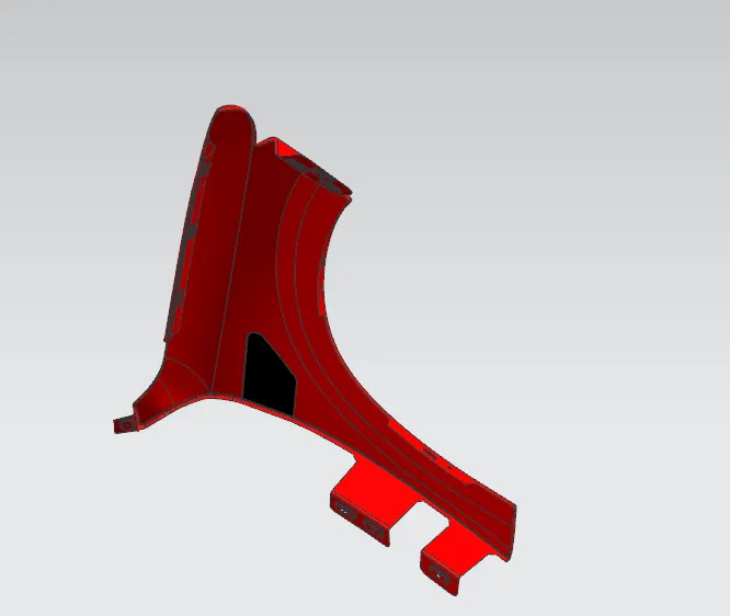
Project 2 Fender
Aim and Objective:- To design a BIW of front fender with given skin data and provide different mountings to it for attachment.
Introduction:- In this chellenge skin data of front fender is provided to design it's BIW. We also need to design A-pillar, sill, side body, etc mounts to attached fender BIW to other BIW components. Mountings are most important part in design of fender, as fender is only part which not welded. So mountings are necessary and should be in perfect position to support fender. Embosses are also provided to add srength to mounting regions. Generally fender is of two types. (a.) Full bumper type and (b.) Half bumper type. Full bumper type of fender was mostly use in older days. Nowadays half bumper type of fender is used. Half bumper type is smaller in size so that less scrap is produced. We can also use longer bumper in this case. The flanges of fender must be at positive angle that is must be tilted outward, so that stamping of fender will be east task. So at least 10 degrees of angle is provided for flanges.
Procedure:- While designing fender sharp corners must be removed. It's flanges must have positive angle to archive easiness in stamping process. Every mounting region must be a flat surface that is mounting region must be in a plane. Following are some critical designing points of fender:-
a. Bumper mounting:- Bumper mounting is provided towards front side of fender. Whole mounting region must be in a plane. 3 embosses are provided to add strength to mounting points of bumper mount. This mounting region is complex in design as it contains sharp edges and different orientation of surface. So care should be taken while designing, sharp corners are rounded and mounting plane must be flat. At last stage of design we need to design fender protection using bumper edge. But in provided skin data bumper is provided in assembly form, so joining of fender protectio of bumper and that of fender was not possible.
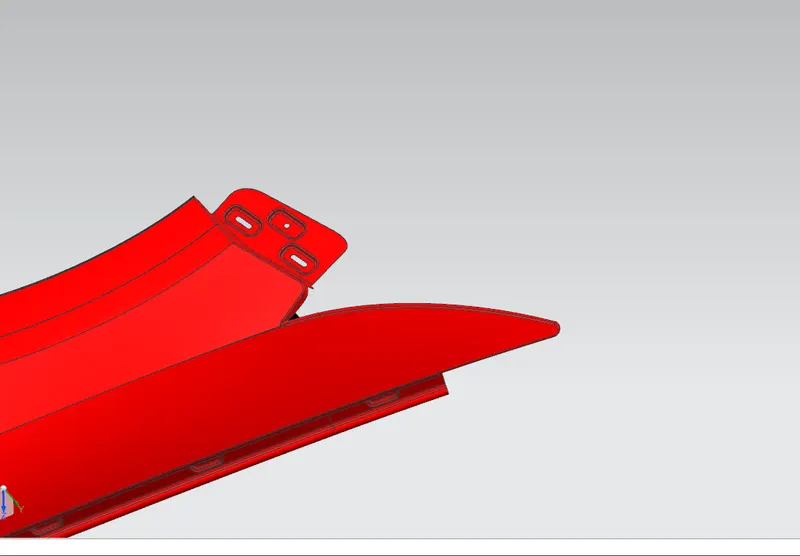
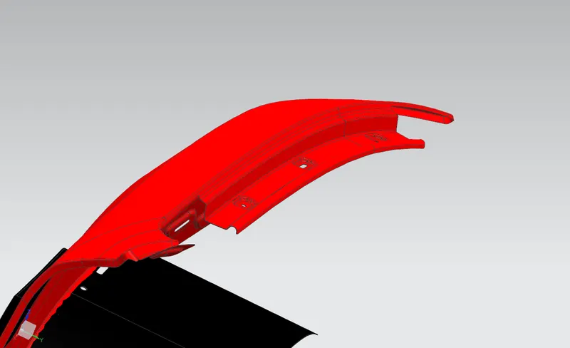
b. Drip area:- It is engine copartment mounting region. Master section is provided for designing of drip area. So it should be followed while designing of fender. 3 embosses are also provided whih adds strength to mounting region. It runs on upper side of fender. But it is not extended till ends of fender. It is offset at 150 mm from front side and 250 mm from rear side. For this reason we need offset planes from extreme ends of fender at mentioned distances.
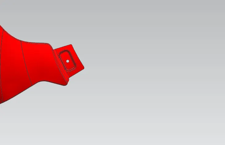
c. A- pillar mounting:- This mounting is present on rear upper side corner of fender. It's design is not much difficult. Corners of mounting region must be rounded. One emboss is provided to add strength to mounting region. FRom given skin data we need to offset a surface at 0mm then using flanges we need to create mounting plane.
d. Body Side and Sill mounting:- To design this mounting a plane is provided in skin data. We need to add flange upto that planes and embosses over that plane. In this step we create two mounting region. One is for body side, which is mounting point of fender to body side panel. While sill mpounting is provided for door. Embosses are also provided which adds strength the mounting.
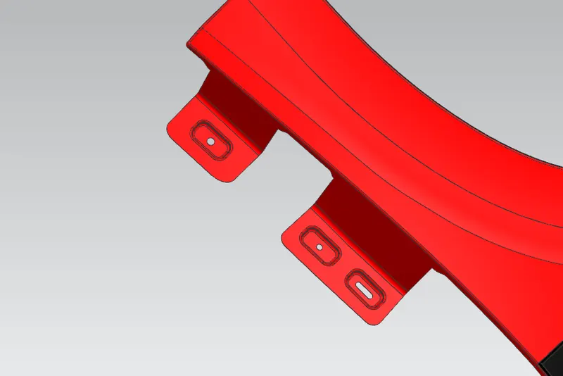
e Fender protection mounting:- Here we do not provide embosses for mounting region. Only a hole and a slotted hole is provided. Same sketch is used to extrude fender protection.
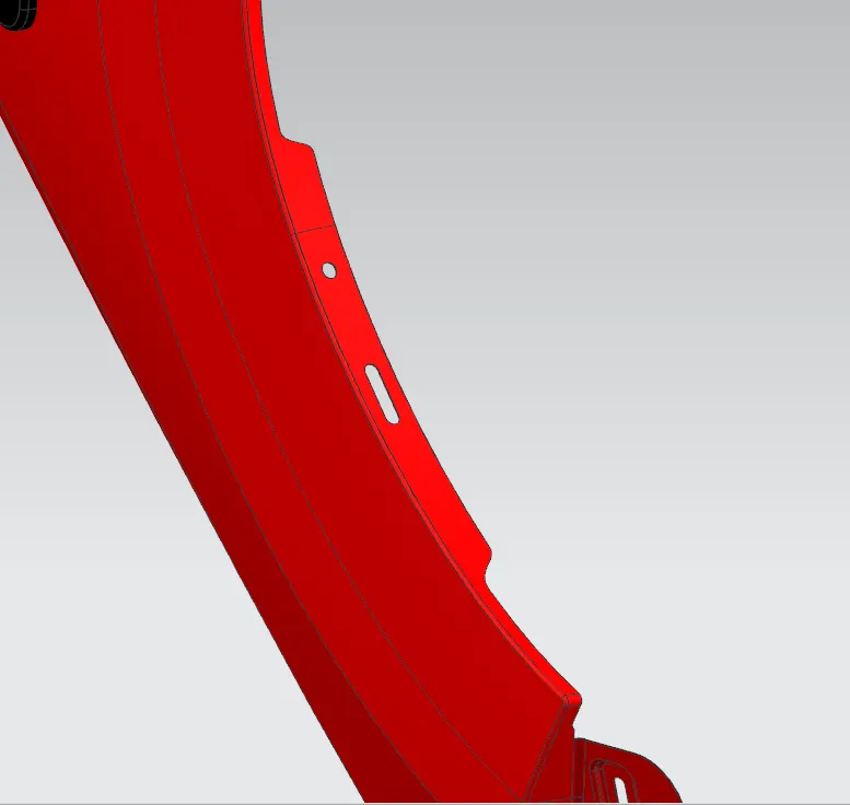
f. Cladding:- Fender cladding is 1 mm thick part present over fender at rear side. For it's designing surfaces are offset at 0 mm and then trimmed off extra surface. It is shwon with black colour.
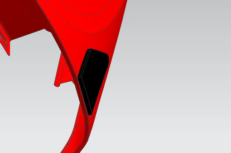
g. Fender protection:- It protects engine compartment from mud, dust. It is present over wheel attaching to the fender. For its design surface is offset at 0mm and thicken offset surface of 1mm. Bumper half of fender protection was not possible as skin data is provided in assembly and it was not possible to connect two assembly with bridge curve.
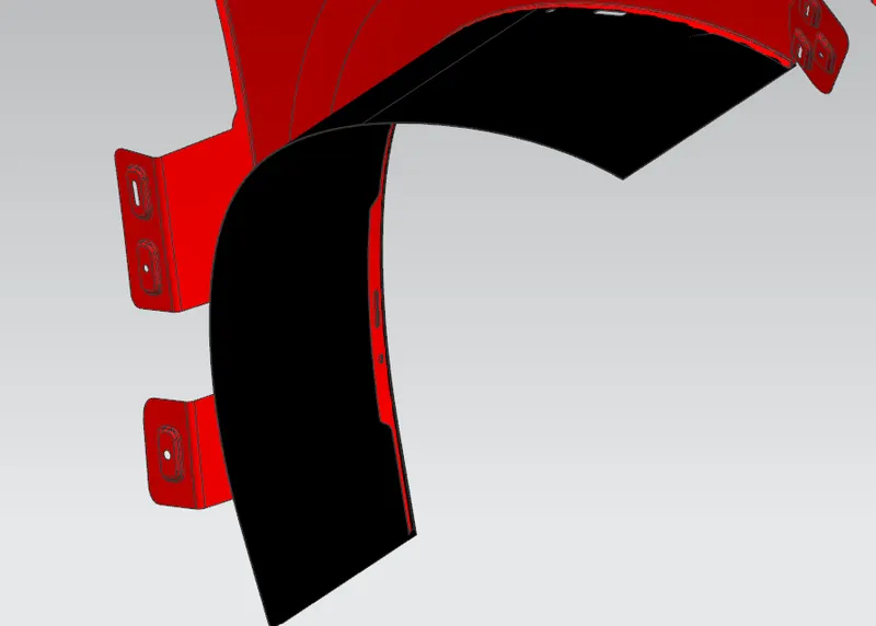
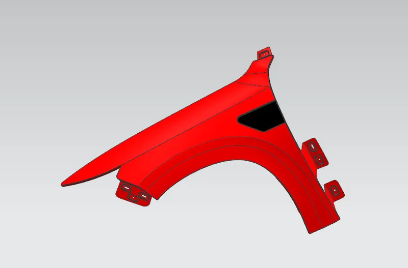
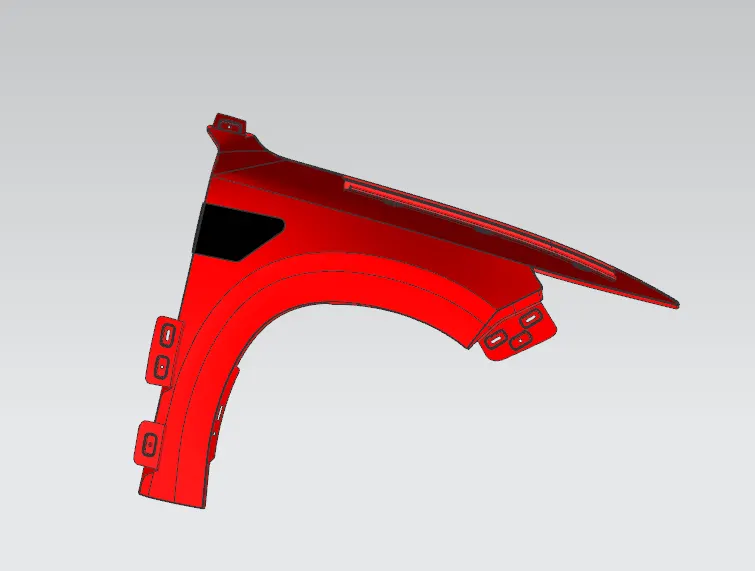
Conclusion:- As above all the mounting are designed. Master section is used for drip region. While other mounts are designed according to manufacturing and design considerations. Blends are provided at required locations. And finally fender of 0.75mm thickness is designed. Following are some pictures of designed fender.
Outside view
Inside view
Iso view