Project 2_Design & Analysis of a Hostel building at Guwahati, Assam
DESIGN & ANALYSIS OF A HOSTEL BUILDING AT GUWAHATI, ASSAM
AIM:
To model, amalyse and design of G+3 Hostel building in ETABS and Foundation in CSI SAFE.
INTRODUCTION:
- Location – Guwahati, Assam
- Function – Hostel block in an academic institute
- The walls will be made of AAC blocks. Other loadings are to be calculated as per the architectural drawings.
- The buildings rests on type 3 soil. Piles of length 10 meters and 500 mm diameter with a load-carrying capacity of 280 KN is to be used.
- The ground floor level will be at a height of 2 meters above the existing site level to avoid floodwater enter the building.
- M25 grade of concrete with Fe500 for longitudinal reinforcement and Fe 415 for shear reinforcement is to be used.
PROCEDURE:
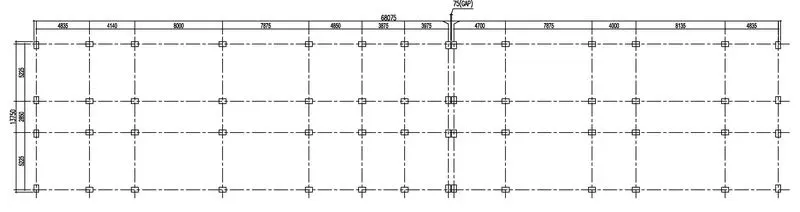
- Firstly before start modeling in etabs we nned to prepare grid drawinging for easy and fast modeling in ETABS
- Using the given architectural drawinf prepare rough grid lines with accurate measurements in AutoCAD
-
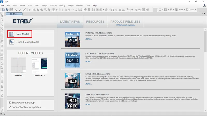
First we have open the etabs software.
-
Then click on the New model option at the left side to create the new model, as shown below.
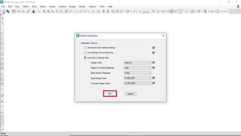
- After that model initialization window will peompt, we have to select 'Use Built-in Settings with' option, as shown below
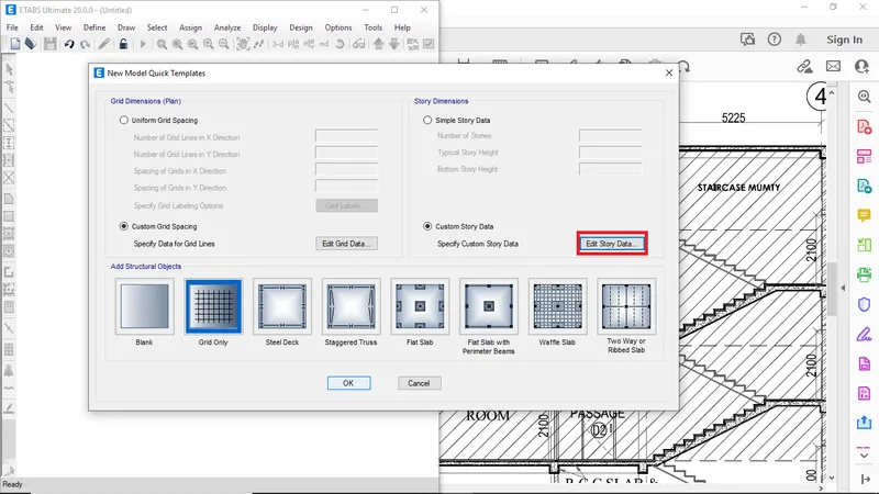
- Then choose grid only to create grids, to add grids click on edit grid data
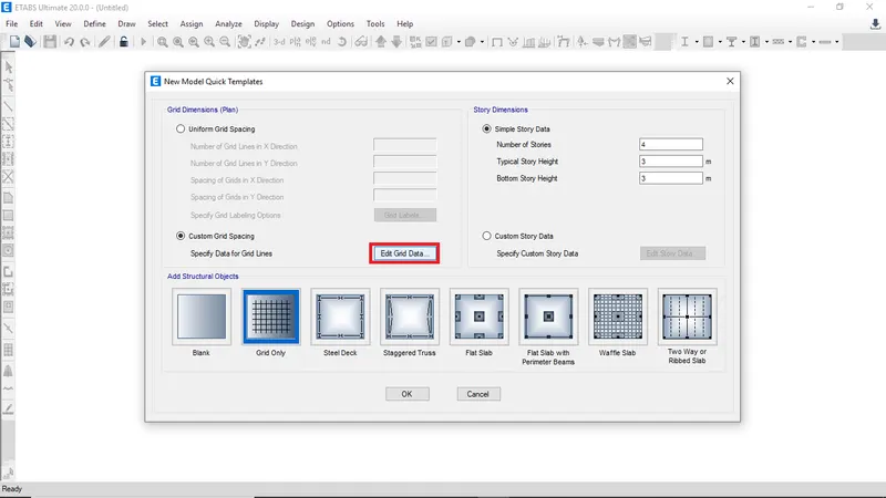
- Enter the X and Y grid data use add button to add extra grids and enter their respective distance
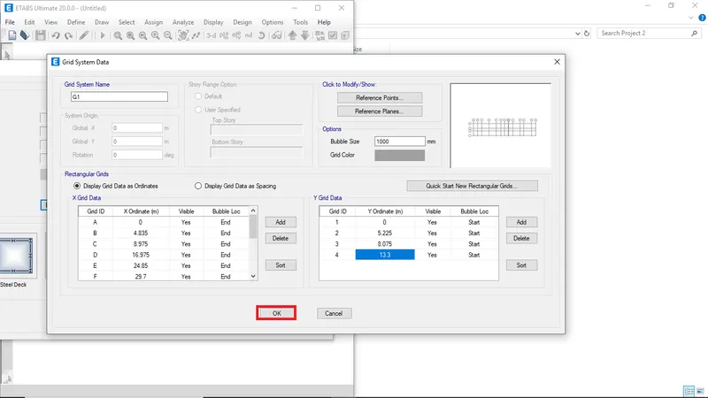
- Then click on edit storey data to add number of story and story height
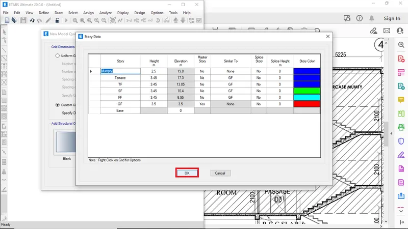
- Enter the required number of story and their height then click ok
- After entering all details and creating the requiries story then click ok
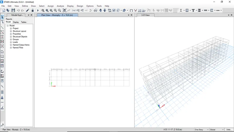
- This is the first etabs user interface. In the left side its the plan view and in the right side its 3d view
- Firstly need to define the material properties, so click on material properties to in define from menu bar to define the material properties
- To add new material property click on add new material
- Then in the opened window select the desired material properties and click ok to create the material
- Then it opens the detailed material property data
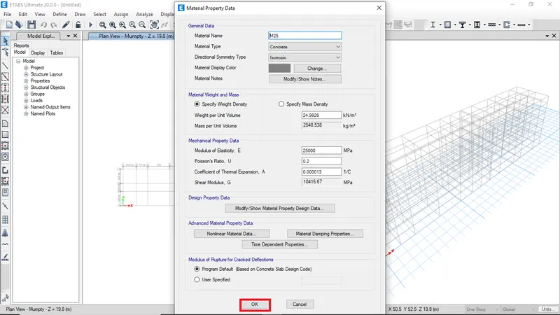
- In the similar way create rebar material and click ok
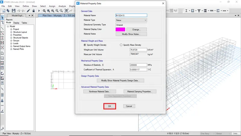
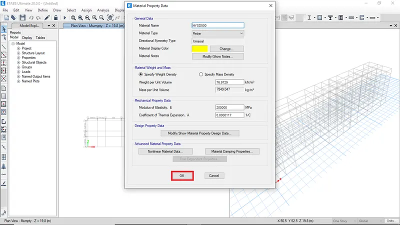
- After creating all the material properties click ok to finish
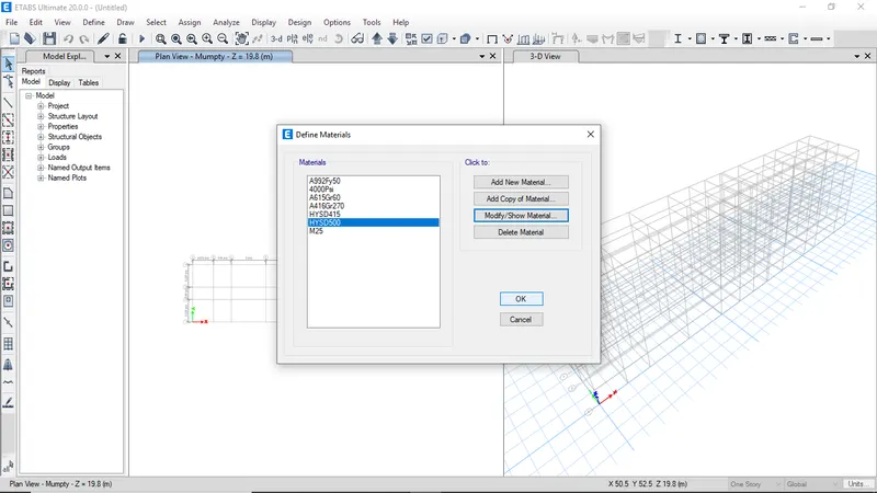
-
After creating the material properties need to define frame sections
-
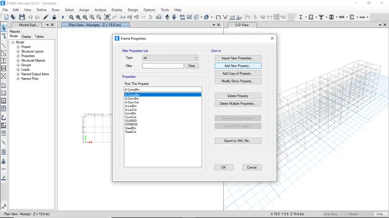
To create frame sections go to define and click on frame section in section properties
- To define new frame property click on add new property
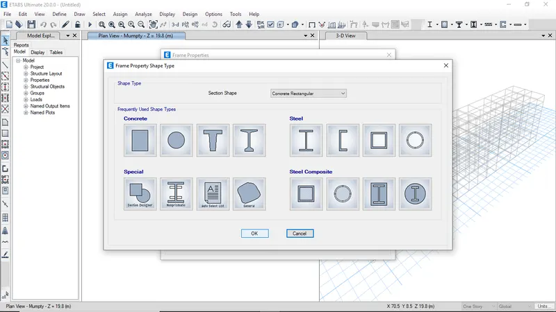
- Slect the rectangular section then click ok
-
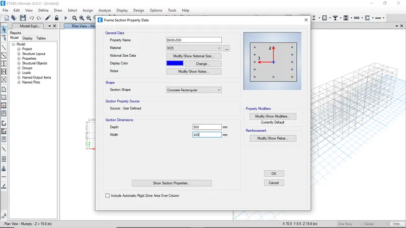
Enter the property name for each frame sections and choose the material grade
-
Enter the depth and widt of the sections
-
click on modify rebar data to specify the rebar data
-
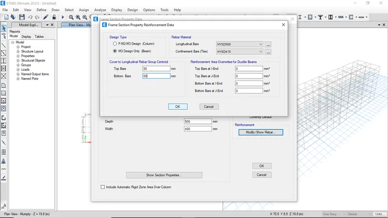
In that choose design for baem if its a column section then choose column
-
For this section its a beam so click on beam and enter cover details
-
Also specify the rebar materilal from the dropdown selection
-
After entering all the details click ok
-
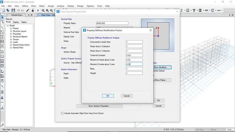
click on property modify to modify the beam peoprty
-
Enter the details as shown in below image
-
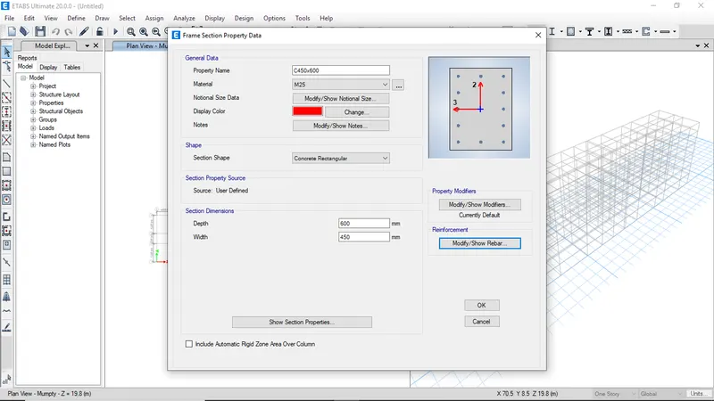
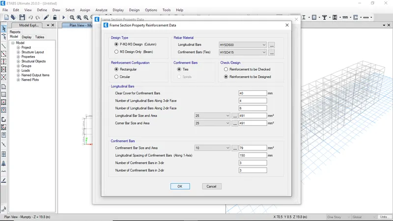
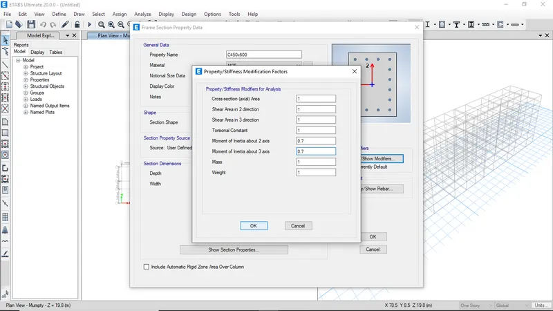
In the same way create another beam section with respective property name and all the details
-
After adding all the frame properties click ok to finish
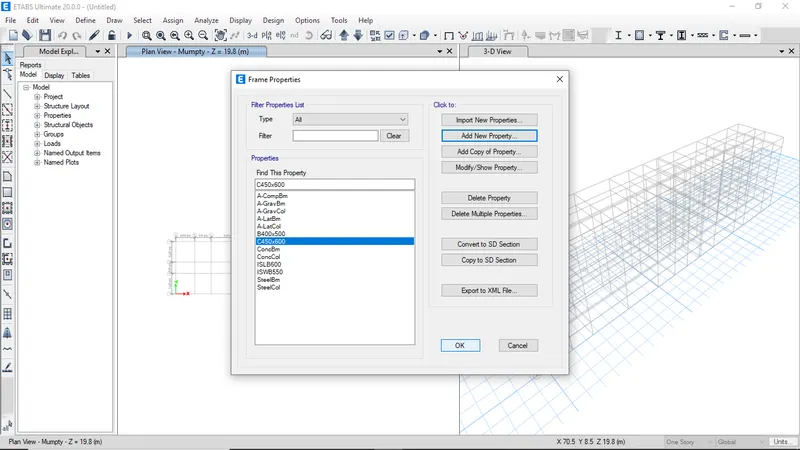
-
Then need to define slab sections
-
For that go to define and select slab sections in sections peroperties
-
click on add new property
-
Add peoperty name for slab
-
Select the slab material
-
And choose modeling type as membrane
-
Then enter the thickness of the slab
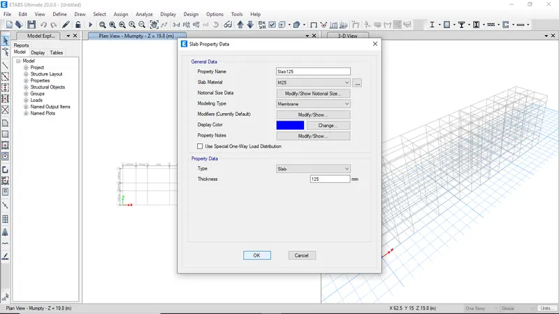
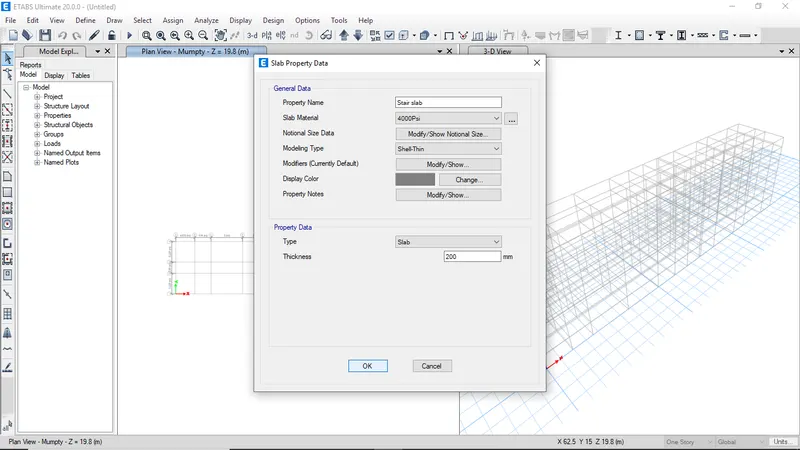
-
Create anothe slab by clicking add new property
-
Then click ok to to finish defining slab sections
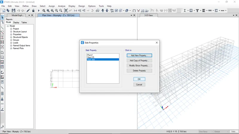
-
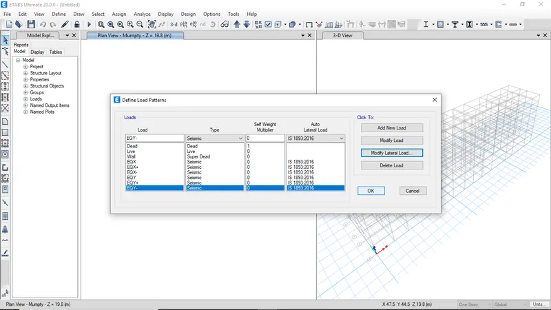
To define load pattern click on load pattern on in define in menu bar
-
click add to add the new loads
-
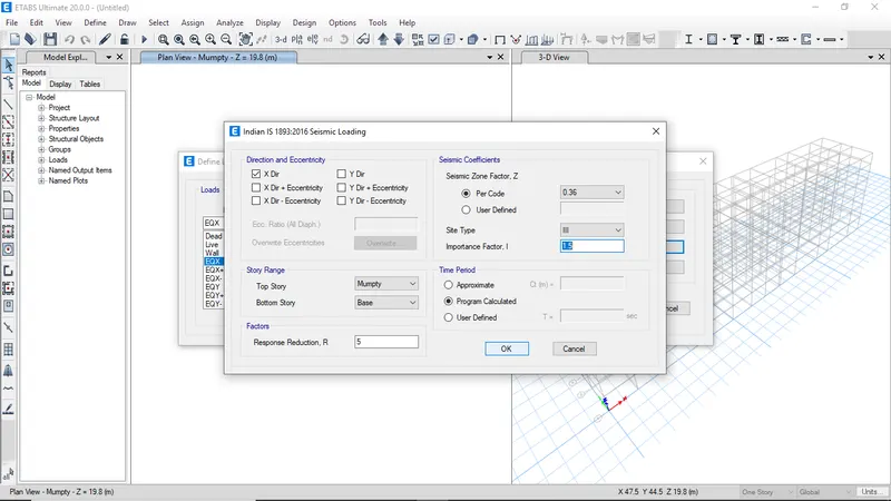
Select the type of load and code from the dropdown
-
After add all the load types click ok to finish
-
After defining all the sections, materials and load patterns need to start modeling
-
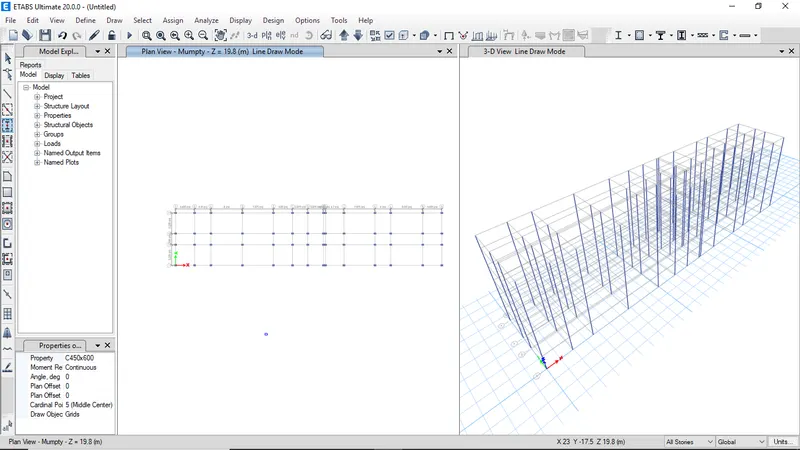
First to ceate columns click on quick draw column in the left side window
-
Befire that make sure the work mode is switched to all stories
-
Then select the column property to draw and draw the columns as per their respective positions
-
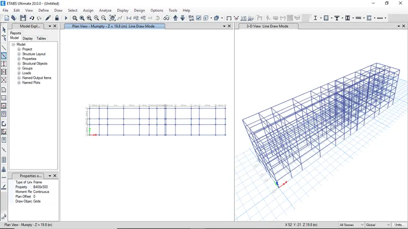
In the same manner create the beams by clicking quickdraw beams in left side panel
-
The beams need to draw in all stories mode
-
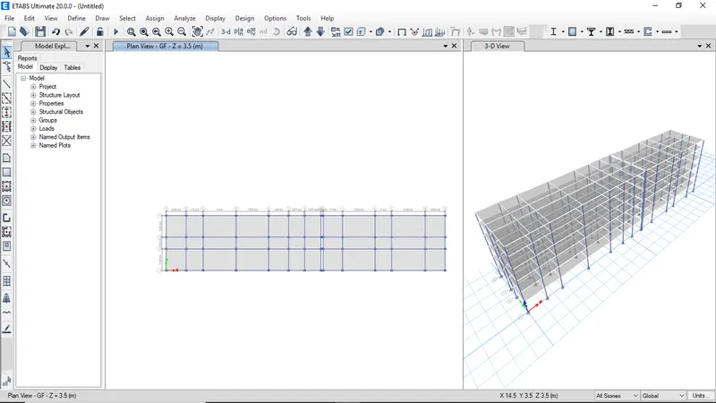
To rotate the columns select the columns in the window
-
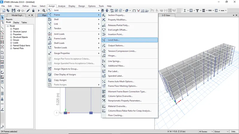
Then go to frame and click on local axes to rotate column
-
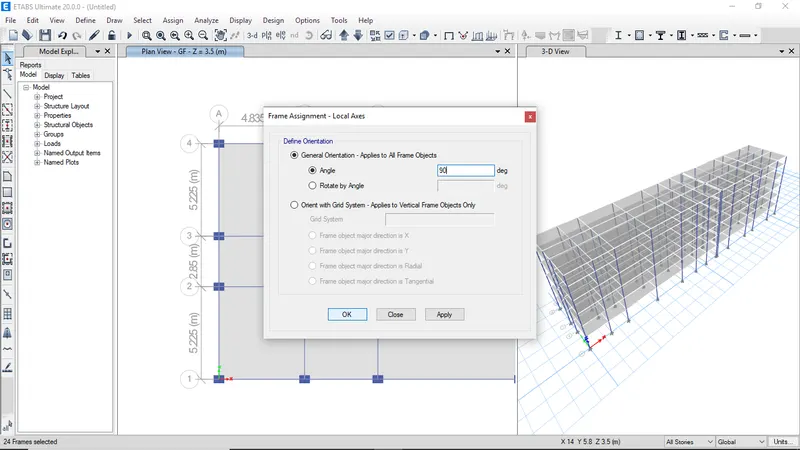
Enter the angle in degree to rotate
-
Then click ok to rotate the column
-
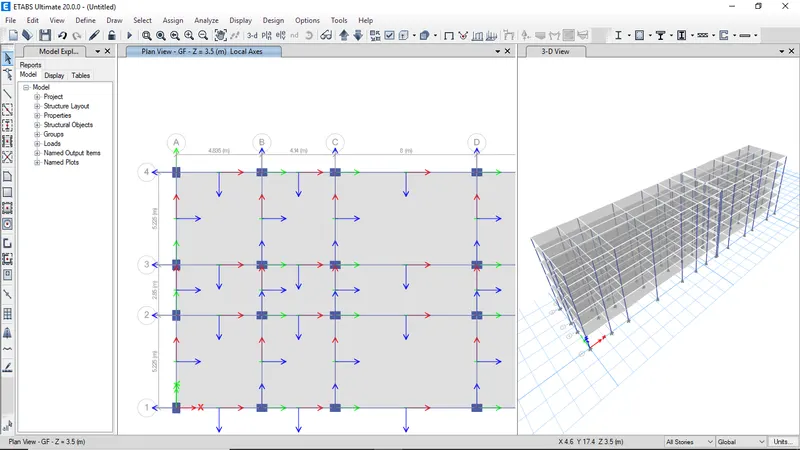
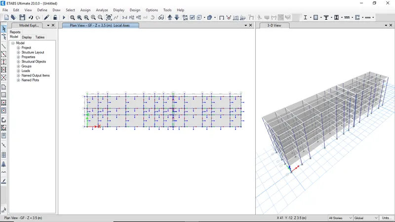
All the column orientation is updated
-
cross check again to confirm
-
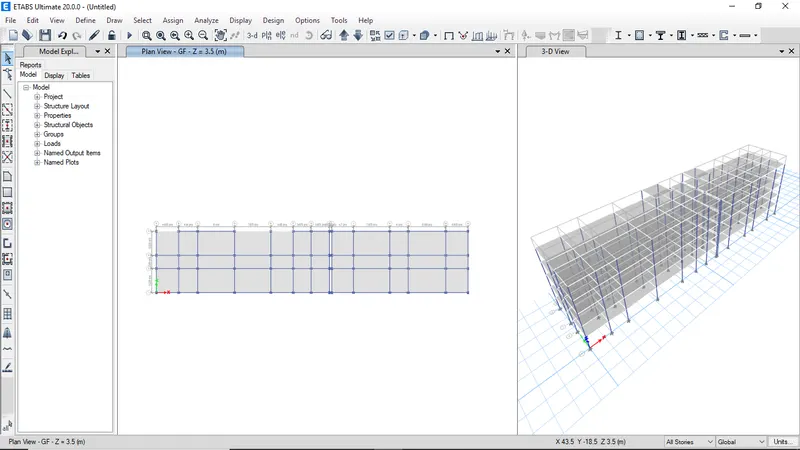
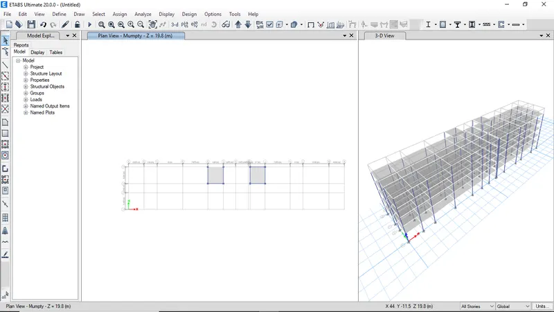
In the mumpty level draw the slab and assign one way load distribution on stair
-
Side vie and 3d view
-
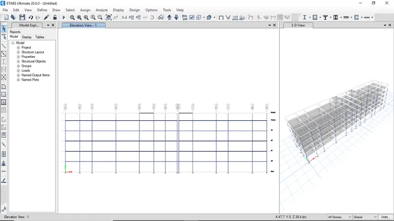
Elevation view
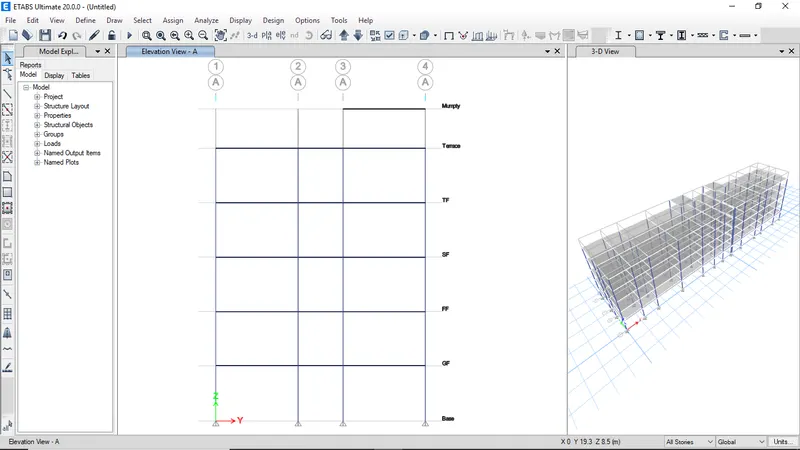
-
To assign the loads now need to select frames
-
The wall load is acting only on frames so selct the frames
-
The frames are selectes by using object type
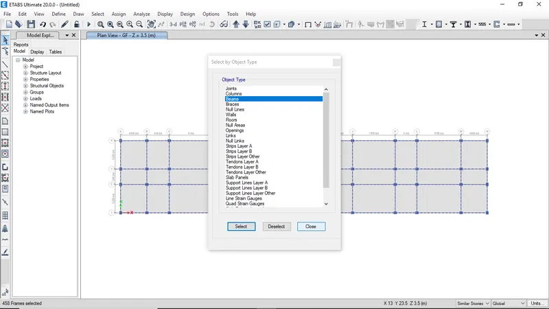
-
select beams and click select
-
Now all the beams are selected
-
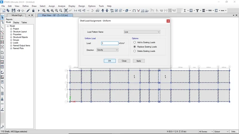
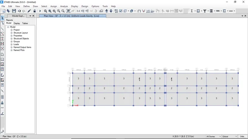
Go to assign, click on distributed load in frame loads in frame load
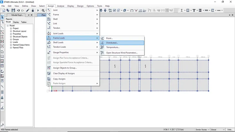
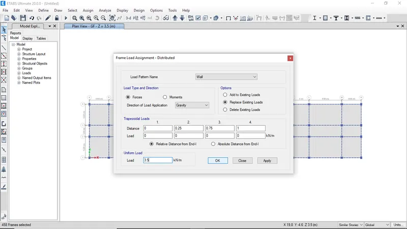
-
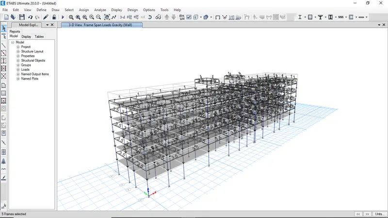
The assigned load will be visible in the given image
-
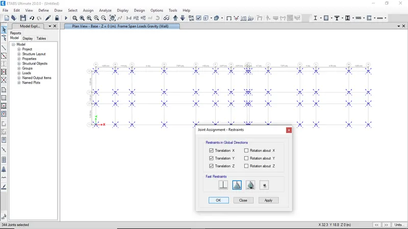
Select all the base joints and assign pinned connection
-
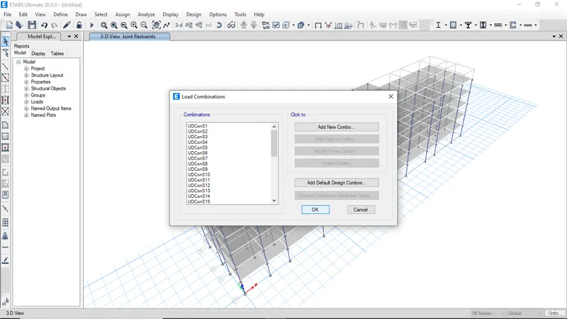
To define the load combination, go to define and click on load combinations
-
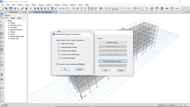
click on add default design combo
-
Then slect concrete frame design and shear wall design to add load combinations
-
Also click on convert to user combination to edit them
-
After creating all the load combinations click ok
-
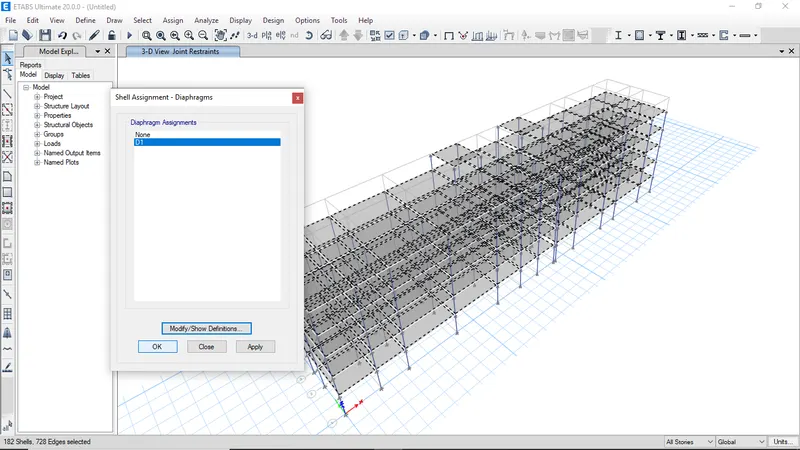
For slabs we need aggign the diaphragms
-
Select the slabs using object selection
-
Then go to assign shell and click on diaphragms
-
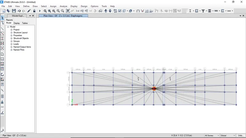
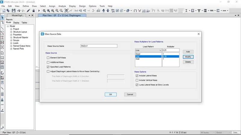
The assigned mass source is visible
-
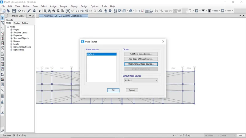
Create mass source data
-
Click ok to finish
-
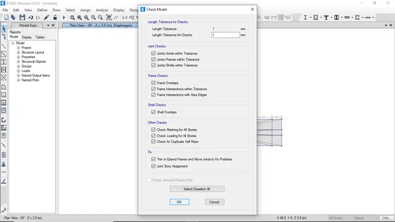
After assigning all the loads need to check the model for error
-
Click on Check model in analyse tab
-
Click on select alland click ok
-
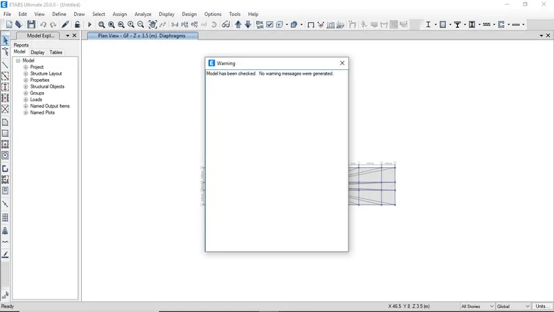
After checking it shows no error if error found then need to correct them
-
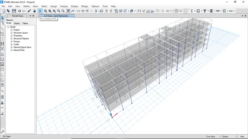
Then click on run analysis
-
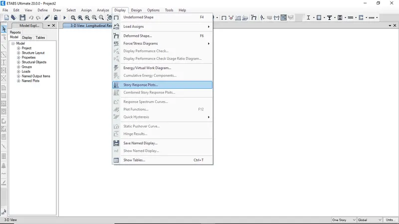
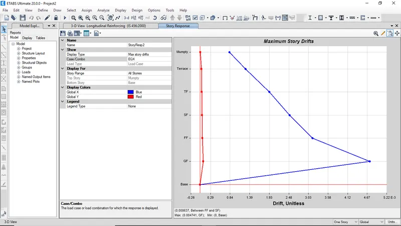
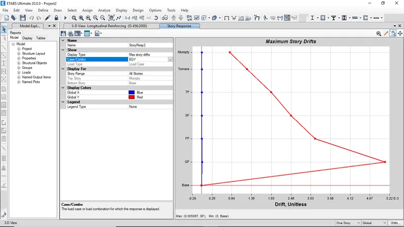
Check the storeydrift
-
Go to display and click on show tables to view results
-
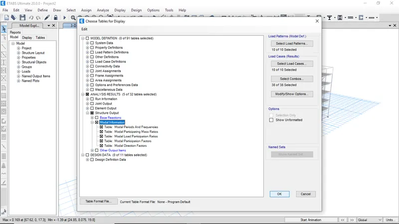
Select modal periods and frequencies to view results
-
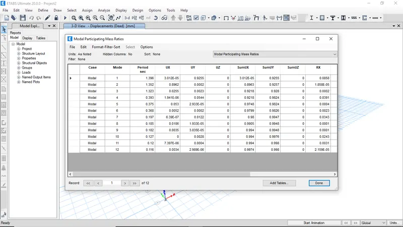
Now the Modal Participating Mass Ratios table will be visible, as shown below.
-
The building has no irregularity
-
The natural time period of building is 1.396 sec
-
After successful completion of analysis then click on concrete frame design.
-
In the concrete frame design click on start design/check.
-
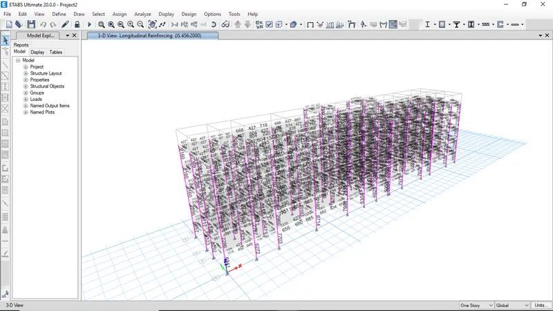
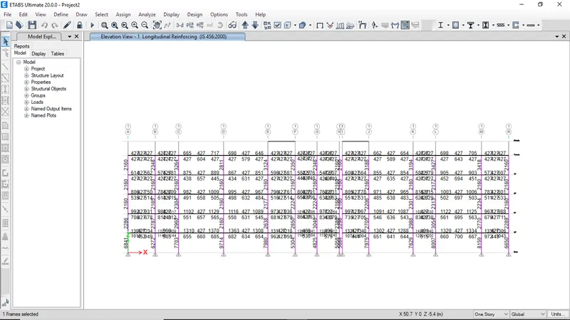
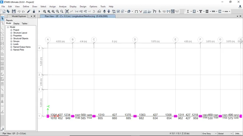
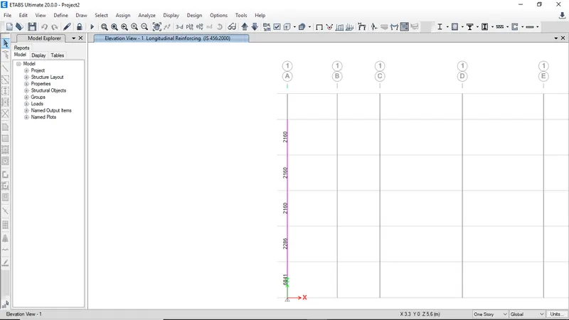
After completion of design check it will display the longitudinal reinforcement details.
-
Then Switch to First floor plan view to view the longitudinal reinforcement results.
-
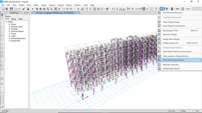
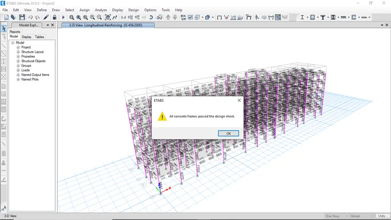
Verify all members passed in design
-
No members were failed so continue to produce detailing and drawing
-
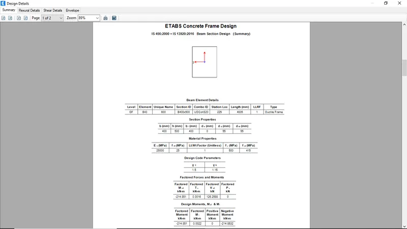
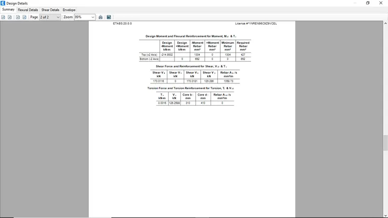
Selected span concrete frame design data
-
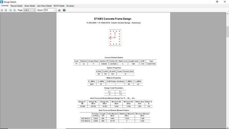
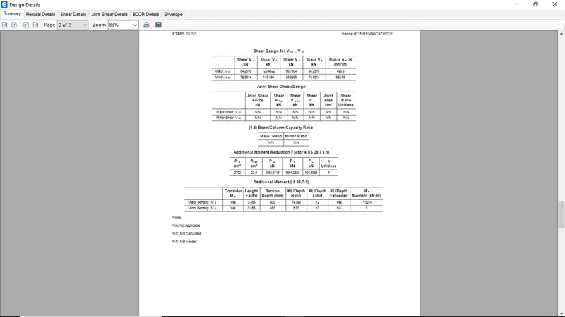
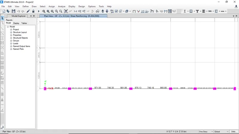
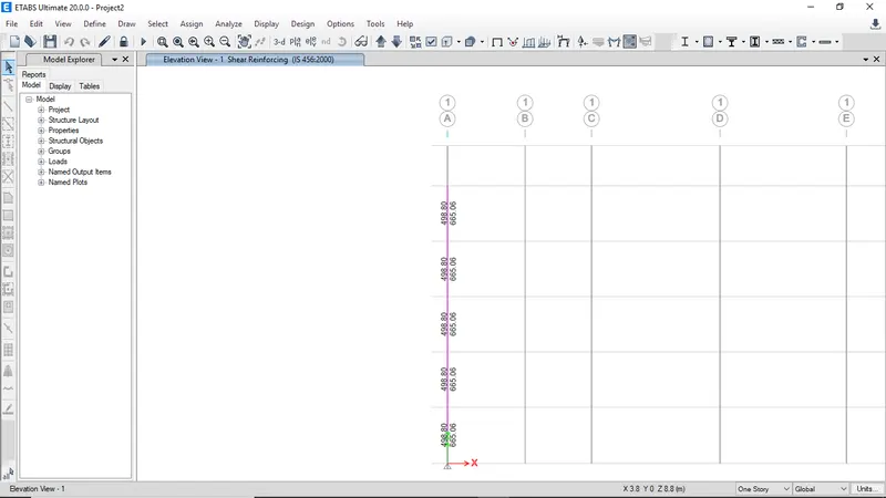
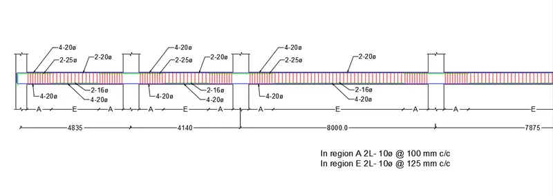
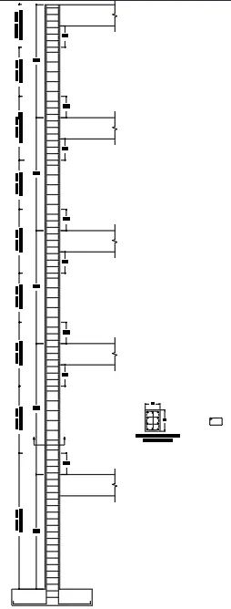
Longitudinal and Shear reinforcement details
-
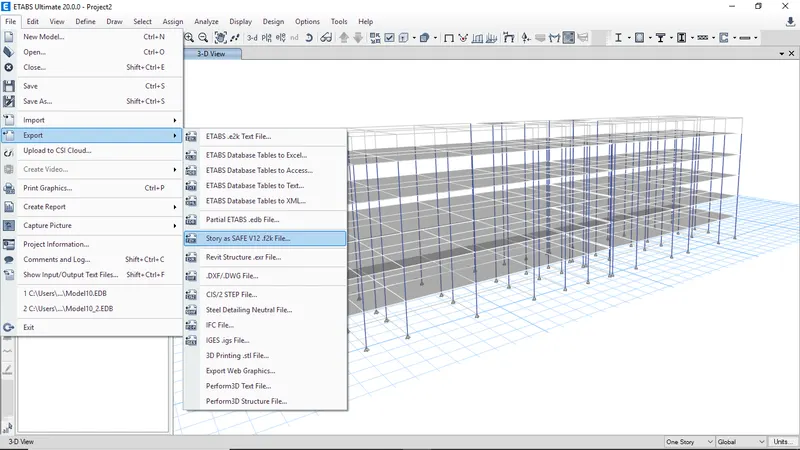
To export load data to safe click export and select .f2k
-
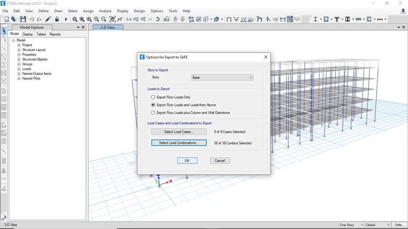
Select base story and check export floor loads and loads from above
-
Open the SAFE software and go to file menu and click on select New Model to create new file
-
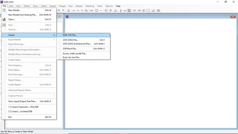
Then click on import to import .f2k file exported from ETABS
-
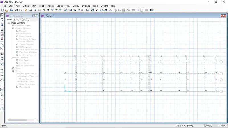
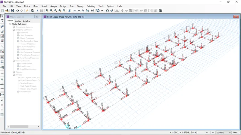
The imported file is now visible
-
Check the loads
-
Firstly need to define the materials
-
To define material properties go to define and click on materials
-
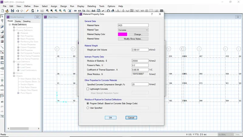
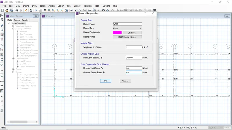
Click on add new materials to add materilas to the existind materials
-
Enter material name and data and click ok
-
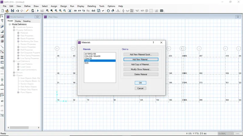
After finishing all material creation click oj to finish
-
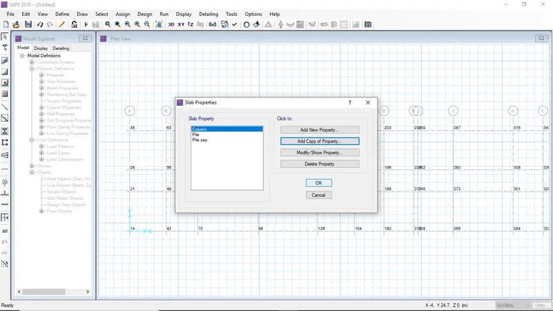
Then define slab properties
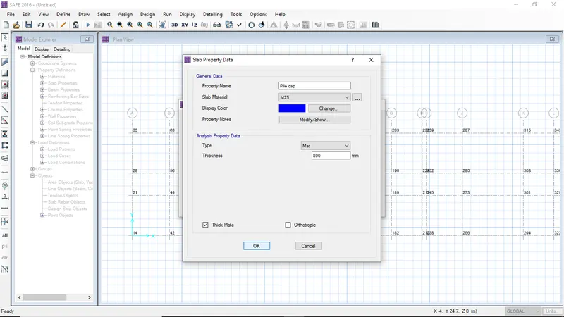
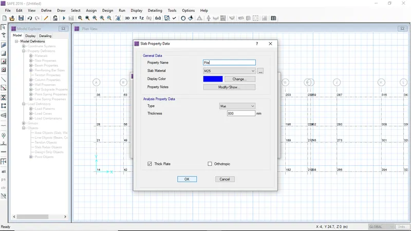
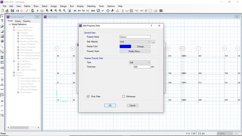
- After defining all click ok
To design pile cap -
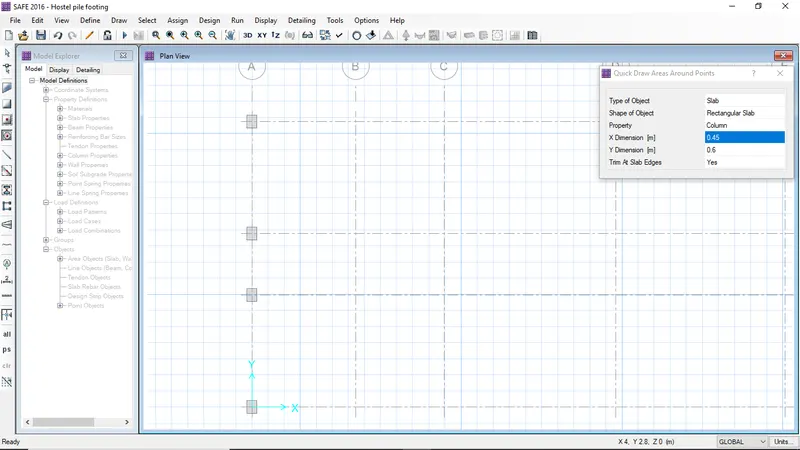
Column size = 450 x 600 mm
-
Pile length = 10 m
-
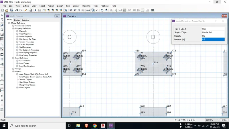
Pile diameter = 500 mm
-
Pile capacity = 280 kN
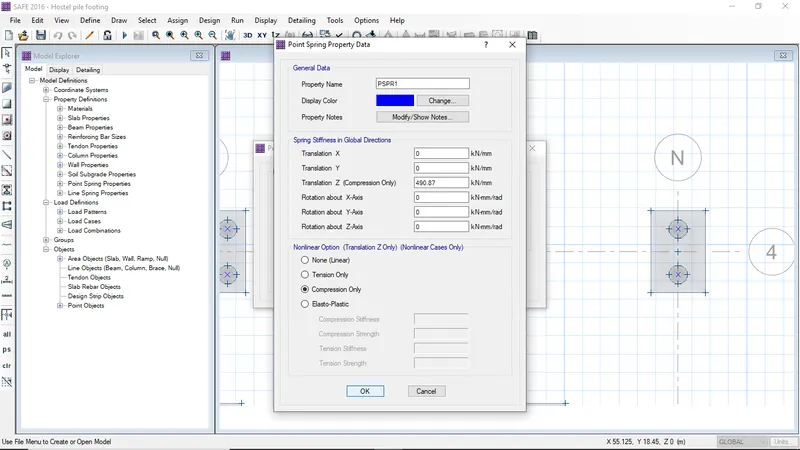
- Elastic modulus of M25 concrete = 25000 N/mm2
- Area of each pile = 196349.5 mm2
-
Spring constant = `(25000*196349.5)/10000 = 490.8` kN/mm2
-
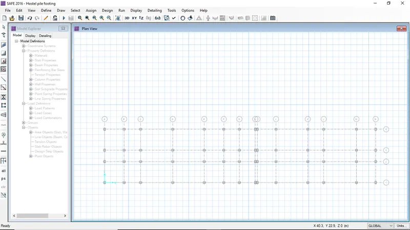
Click on draw slab and and select property to draw column, pile cap and pile
-
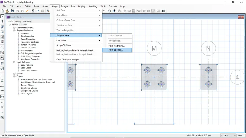
Select all pile points to assign point spring
-
Then click ok to assign
-
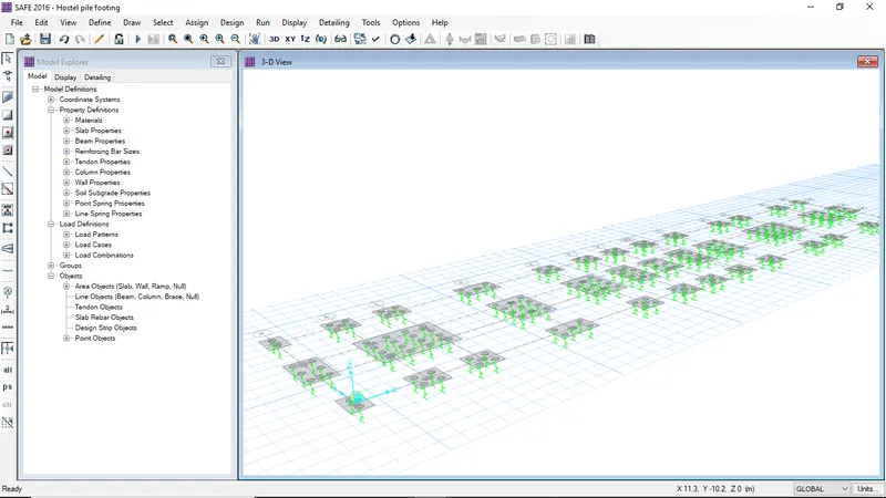
The assigned point spring is visible
-
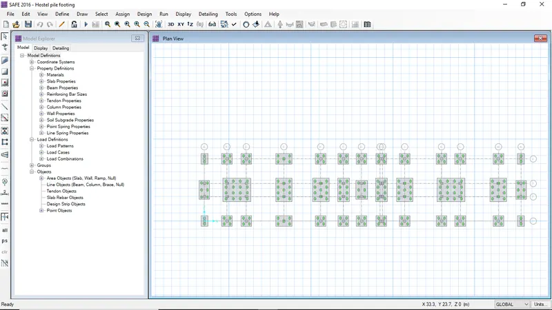
Plan view of pile group
-
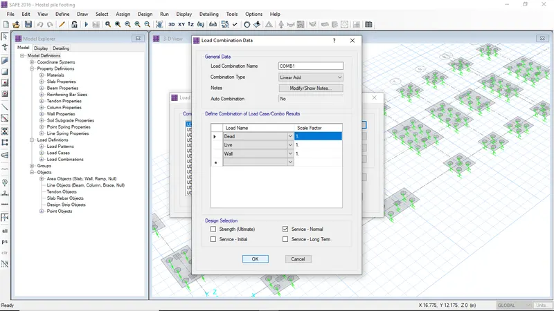
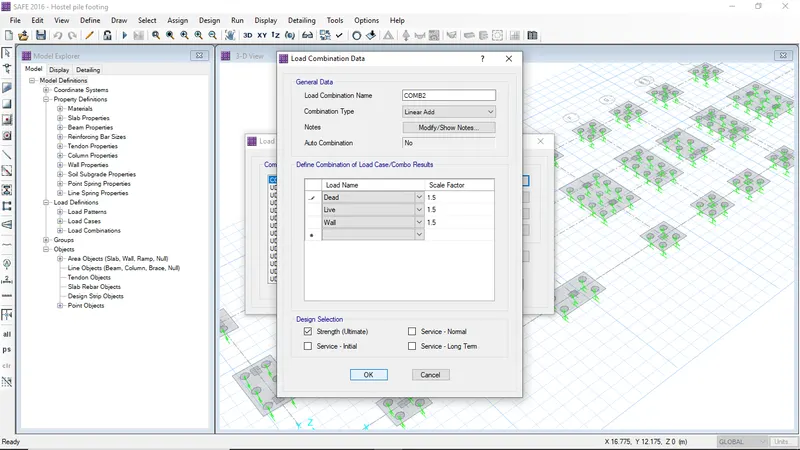
Create load combinations
-
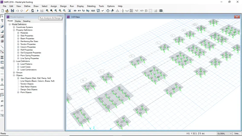
Click run analysis
-
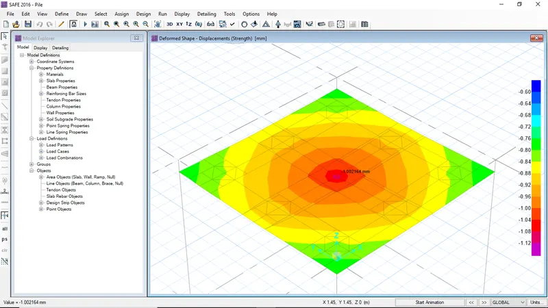
The deflection is within limit, hence safe
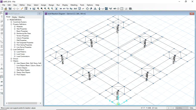
- As all the pile reaction forces are according within the limit.
- The pile reaction forces not exceeding 280 kN, Hence safe
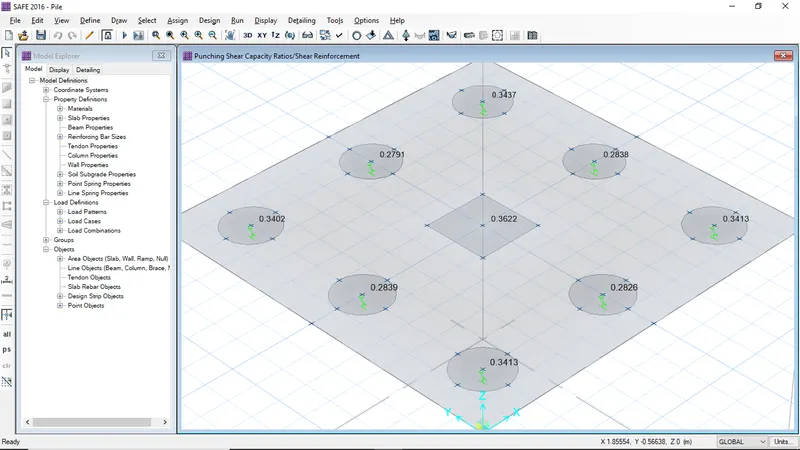
- Also, all the punching shear values are less than 1, So its safe
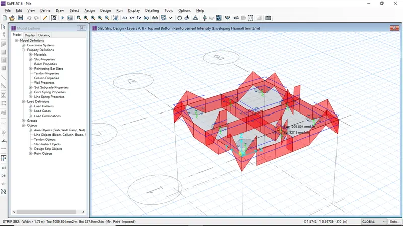
- Flexural reinforcement details
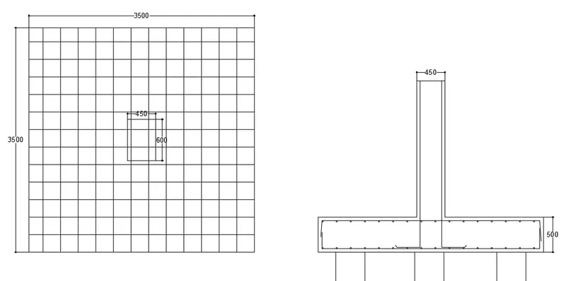
RESULT
The G+3 Hostel building is modeled, amalysed and designed using ETABS and Foundation in CSI SAFE.