Project 2 - Crush analysis of aluminium Tube
Setup:
Geometry:
-Open spaceclaim and create the geometry > create square section 40mm x40 mm using sketch > pull the section for 20 mm height.
-click top s/f and click on circle sketch > Create circular c/s with 30mm dia > Pull the perimeter of circle to get a hollow section.
- Now click on peeimeter and create another square section of 40mm x 40mm > Move it 1mm away from tube and pull it 0.95 mm in direction of tube.
-Rename S/f as Tube and new solid as Rwall
Material:
-Add aluminum Non Linear material to the Tube.
-Add structural steel material to rigid wall and block and switch the behaviour to rigid.
Mesh:
- Create a mesh using a face sizing of 3mm.
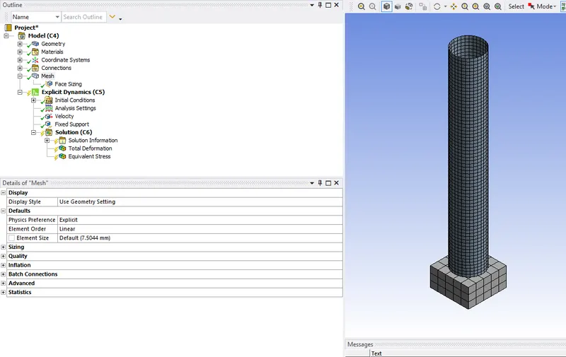
Analysis setting:
-Provide end time as 6e-03
-Provide fixed support to Rwall with body selection.
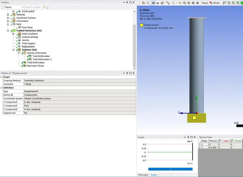
-Provide velocity to common face of rigid wall and tube in the direction of tube.
-Insert Displacement and Lock the movement of tube end perimeters in transverse directions.
-Insert anotherDisplacement and Lock the movement of block in transverse directions.
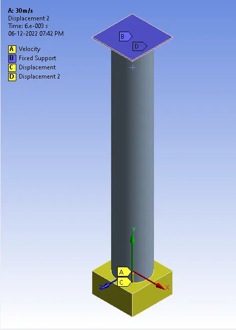
-Provide velocities in each case as 30, 40, 50 and 60 m/s respectively.
Results:
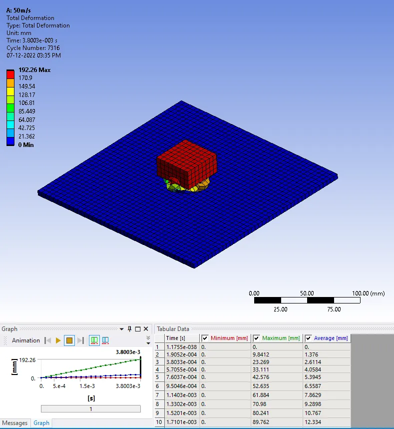
The Maximum deformation and stresses on the tube (comparing the results):
| Maximum deformation(mm)(Tube only) | Maximum stress(Mpa)(Tube only) | |
| Case 1=30m/s | 198.35 |
561.54 |
| Case 2=40m/s | 199.56 | 568.96 |
| Case 3=50m/s |
198.27 |
610.98 |
| Case 4=60m/s | 195.48 | 636.56 |