Week 1 Spur Gear Challenge
Objective 1: To carry out a static structural analysis to find out Equivalent stress, Total deformation and Stress intensity(Learn about what stress intensity is). Find location for possible fracture.
- Case 1: Using Cast Iron(ductile) as material
- Case 2: Using Cast Steel as material
- Case 3: Using Cast Bronze as material.
Objective 2: To write a detailed report comparing the results of the three cases and recommend a material based on these results.
CASE SETUP AND EXECUTION results:
Step 1: Engineering Data
- In this option you can find a list of generally used materials and you can add material of desired choice/specification. Look for Cast Iron, Cast Bronze & Cast Steel. Double check for mechanical properties and make sure you have valid data entered.
- You can also add custom materials and specify the mechanical properties of materials.
- Alternatively you can open Model, click on material and search for material name and then click the add sign to include this material into the drop down list of material assignment.
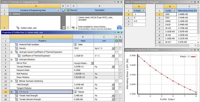
The Engineering data considered for the materials is depicted below:
Fig 1: Mechanical properties for Cast Iron (Nodular/Ductile):
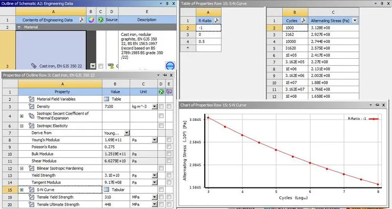
Fig 2: Mechanical properties for Cast Bronze:
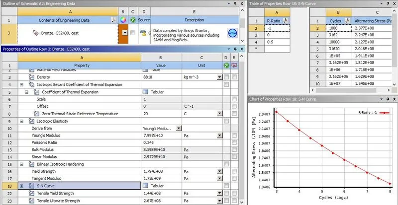
Fig 3: Mechanical properties for Cast Steel:
Step 2: Geometry
- Right click on geometry and Import the spur gear .stp extension file
- Rename the Static Structural tab as Case 1 and follow the similar process for Case 2
- Update the Static Structural tab and proceed to model.
Step 3: Connections
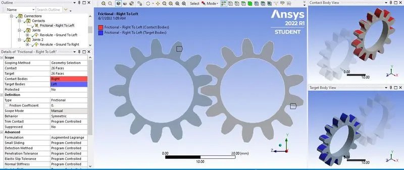
- Contacts:- Reselect all the faces of the Right and Left gear (26 for 13 Tooths) and properly define the contact and Target faces.
- Change the Type of contact to Frictional and Behavior to symmetric.
- Use augmented Lagrange in advanced formulation methods. This is used to avoid the effect of friction on gears and avoid its movement from its location. It increases the stiffness and avoids unnecessary chartering of models.
- Change the interface treatment to adjust to touch.
Fig 4: Showing contact settings
- Joints:- Insert Joint and specify the connection as Body to Ground
- Select the inner faces of gear geometry to scope accordingly and define the type of joint as revolute for both gears.
Fig 5: Showing assigning Joint with scoping geometry.
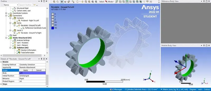
Fig 6: Showing other Joint settings
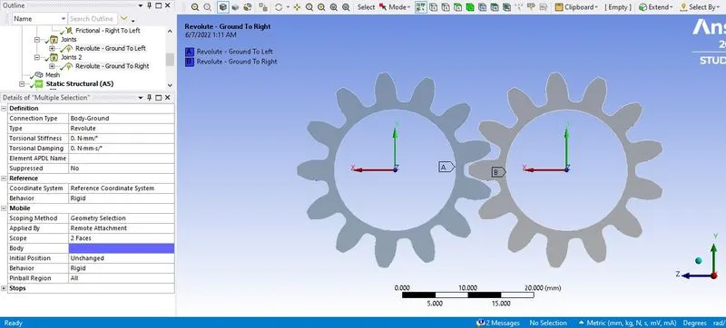
Step 4: Model
- In this step you can assign the material to geometry and generate mesh with desired accuracy of required solution.
- Within the Mesh option inside the Details of Mesh under default option you can specify Element size and see if the mesh quality is as per required standards. You can watch for aspect ratio less than 5 which is good but should not be more than 10.
Fig 7: Showing Mesh Quality using Aspect Ratio
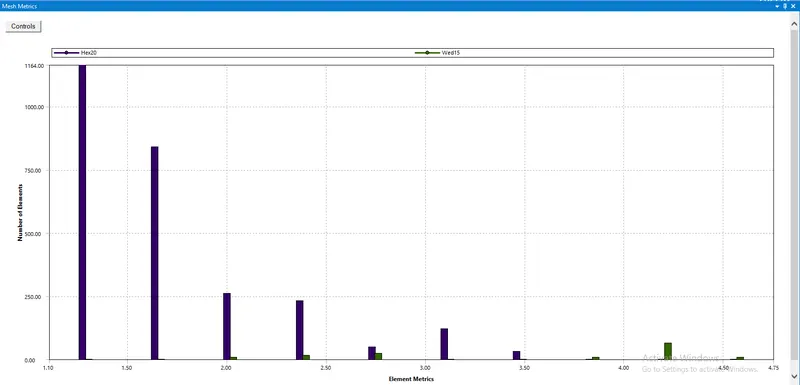
Step 5: Setup
- In analysis settings we are going to divide it in six steps and look at the stresses and forces developed during 180 deg rotation of gear.
- Enter 6 as the number of steps and select all the steps simultaneously and switch on the large deflection in solver controls.
- Turn on auto time stepping and define by time
- Put the initial time step as 0.2, minimum time step be 5e-2, and maximum step time be 0.5.
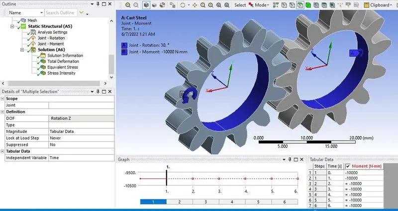
- Right click on static structural and insert joint load and assign scope to the joint and define its type by rotation and other by moment.
- Assign tabular data for rotation angle for one gear and tabular data with moment values for other gear in the opposite direction of first gear.
Fig 8: Showing Analysis Settings.
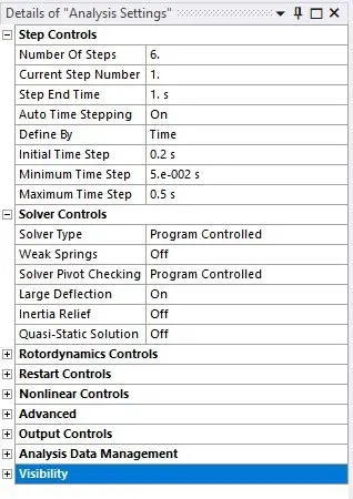
Fig 9: Depicting assignment of Joint Rotation and Joint Moment allocation.
Step 6: Solution
- Observe results for Equivalent Stress distribution, Total Deformation and Stress intensity to observe the values and data.
- Observe for probes which point out Maximum and Minimum values of corresponding data.
RESULTS OF CASE 1, CASE 2 & CASE 3 WITH IMAGES FROM SIMULATION:
Fig 10: Showing Analysis results for Equivalent stresses in material;
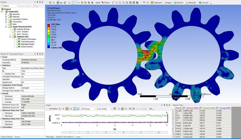
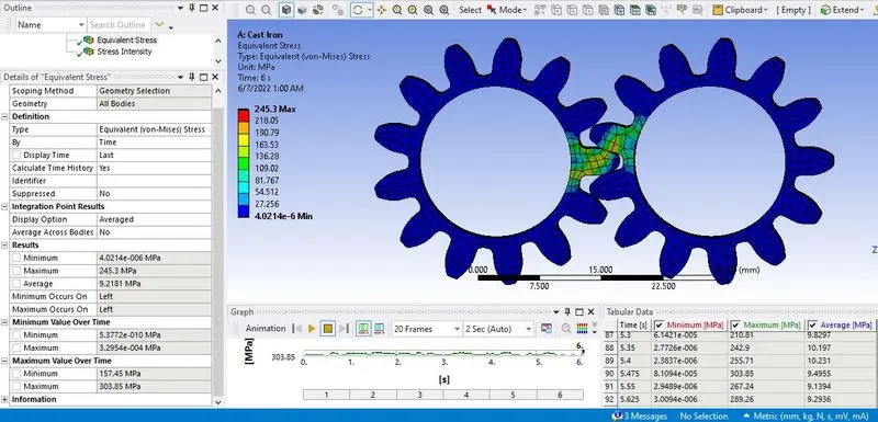
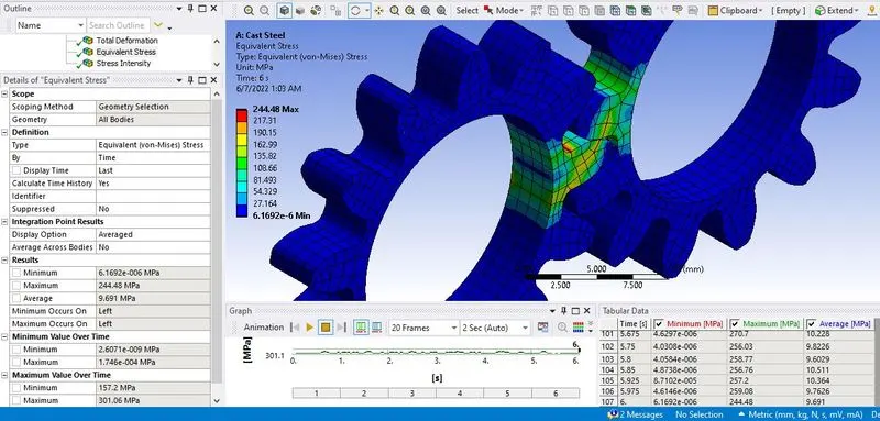
Fig 11: Showing Analysis results for Total Deformation in material;
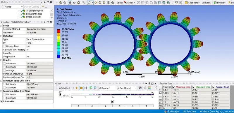
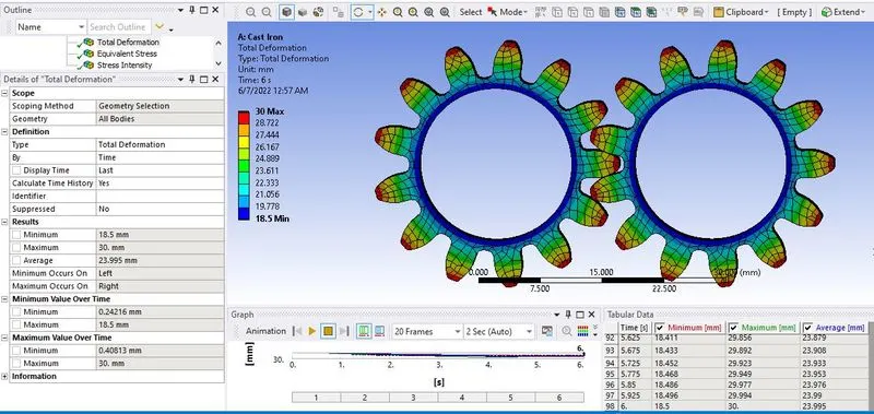
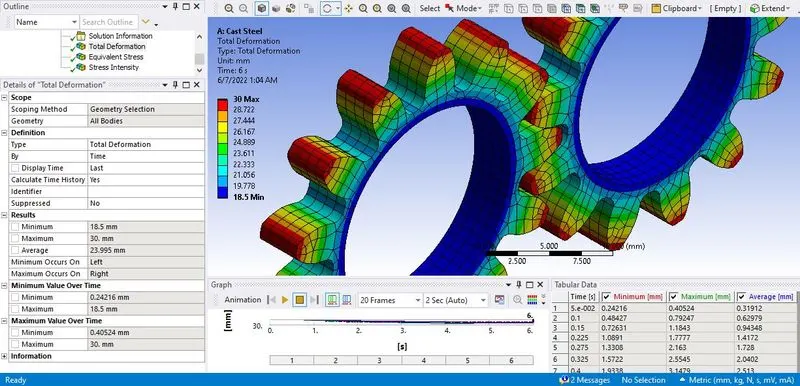
Fig 12: Showing Analysis results for Stress Intensity in material;
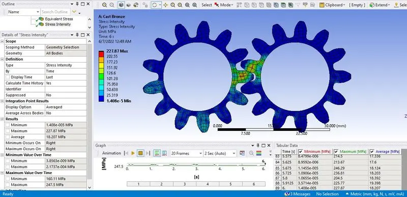
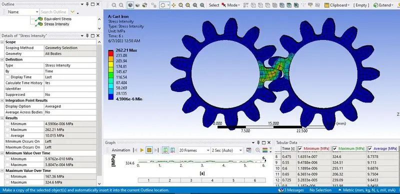
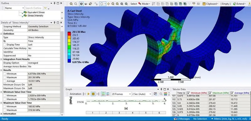
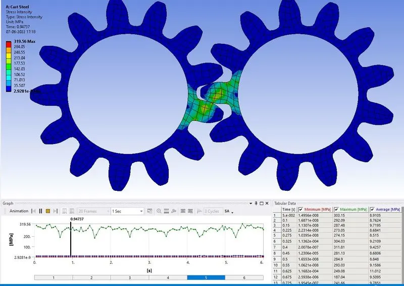
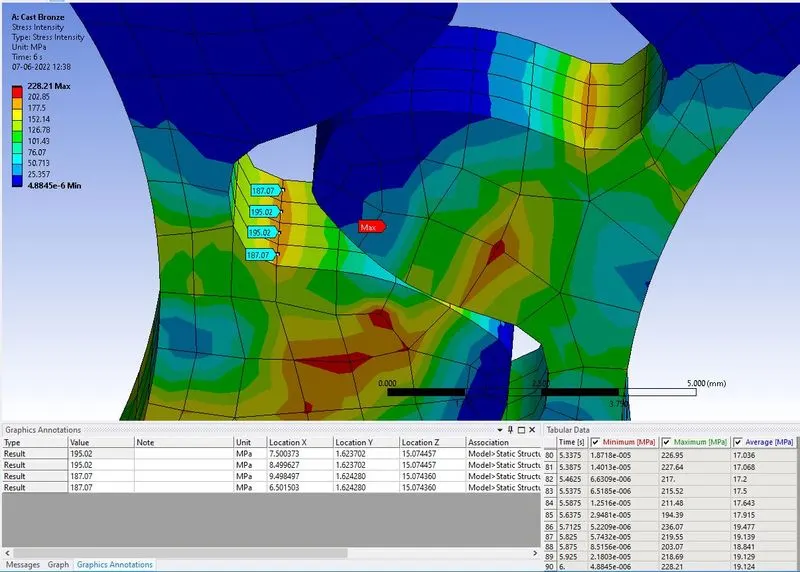
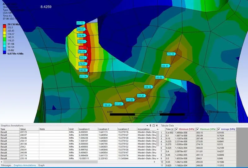
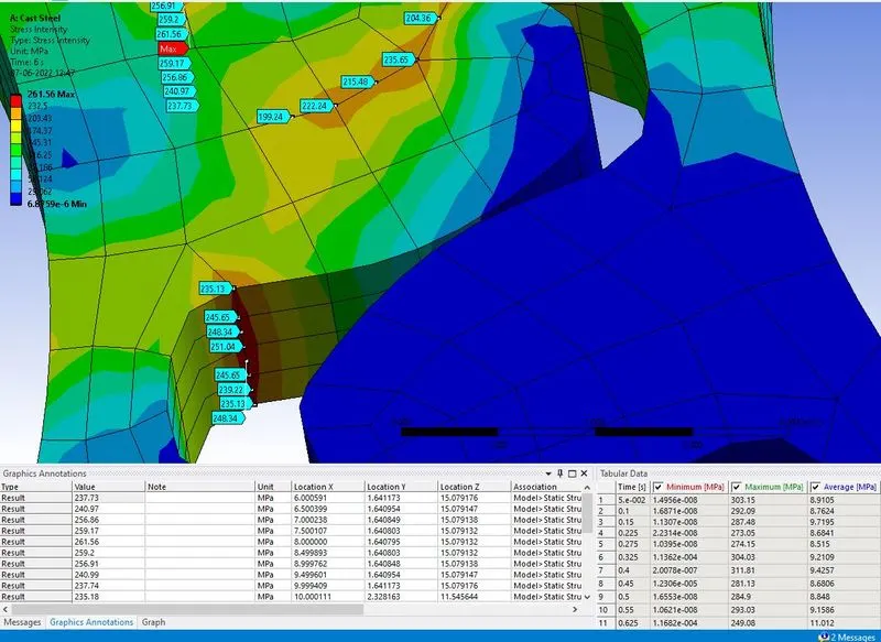
Simulation results for Max Stress intensity & Location for possible fracture in Materials:
Fig 12: Showing location for possible fracture in Materials:
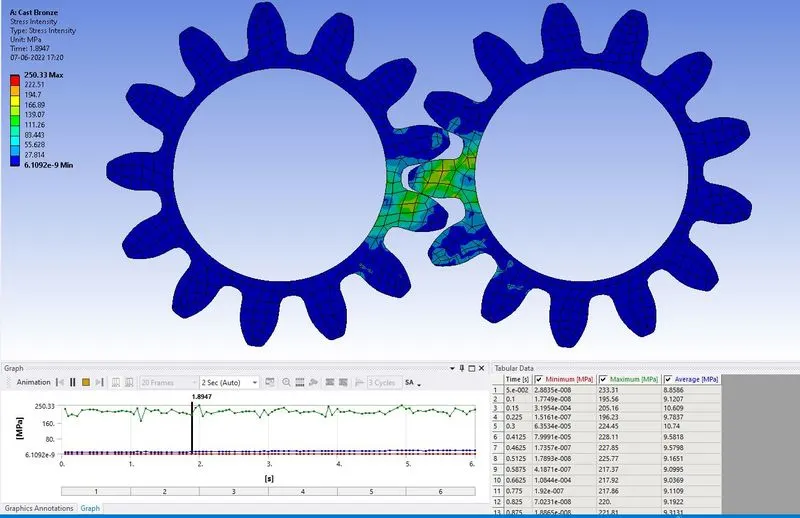
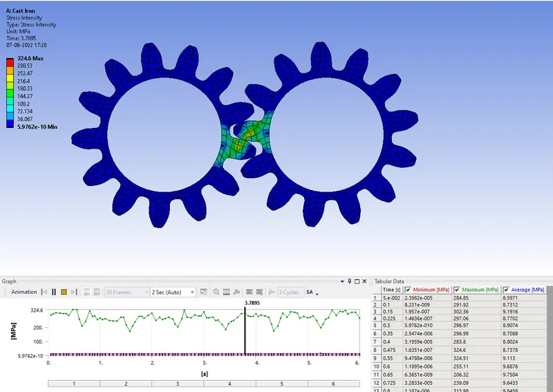
Results Comparison:
|
Material |
Total deformation (mm) |
Equivalent stress (Von-Mises MPa) |
Stress Intensity Max (MPa) |
Stress Intensity Avg (MPa) |
Tensile Yeild Strength (MPa) |
Y Modulus (GPa) |
UTS (MPa) |
|
Cast Steel |
30 | 244.48 | 319.56 | 261.56 | 349 | 203.4 | 505 |
|
Cast Iron |
30 | 245.3 | 324.6 | 262.21 | 310 | 169 | 448 |
|
Cast Bronze |
30 | 199.2 | 250.33 | 228.21 | 144 | 80 | 267 |
Report:
Based on Result comparison we can see that stress intensity in cast bronze has reached almost to its Ultimate Strength values and thus makes it less suitable for this application. Stress intensity limits reached in Ductile Cast Iron is better than Cast bronze but values are similar to that of Cast Steel. From analysis point of view it seems that Cast Steel has better metrics in suitability for this application. The Equivalent stress (Von-Mises), Stress Intensity (Avg and Max) reached in Cast steel is less than Cast iron. So from analysis point of view Cast steel is recommended material for this case.
**NOTE: These results are based on values of mechanical properties which are considered and selected for purposes of material comparison and analysis development.
But consider other factors of nodular iron which is also called ductile iron, the graphite is present as tiny balls or spheroids. Because the spheroids interrupt the matrix much less than graphite flakes, nodular cast iron has higher strength and toughness than gray cast iron. The formation of nodules or spheroids occurs when eutectic graphite separates from the molten iron during solidification. The separation of graphite in nodular form is similar to separation of graphite in gray cast iron except that the additives facilitate the graphite to take nodular shape. The Ultimate Stress values range from 450 Mpa upwards. This will provide different results and might suggest cast iron as better material for this case.