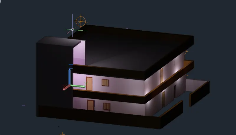
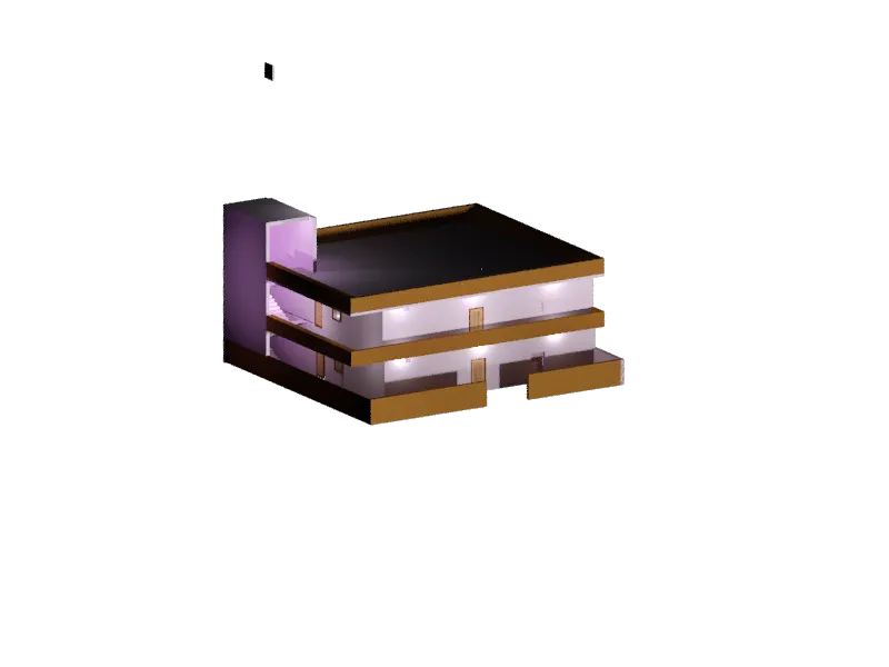
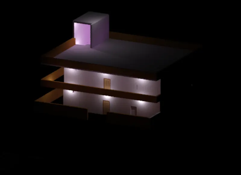
Project 2_Creating a 3D rendered model for a Residential Building in AutoCad
AIM & INTRODUCTION: To creating a 3D rendered model for a Residential Building in AutoCad
PROCEDURE:
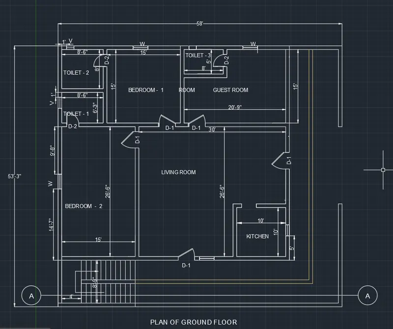
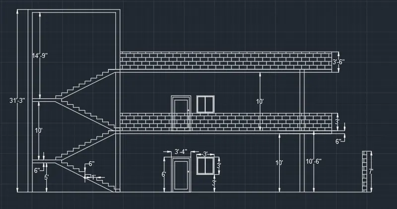
1)TO CREATE PLAN AND SECTION:
COMMANDS USED :
- Layer
- Line
- PL
- XL
- Offset
- Rectangle
- Tool pallet
- Array
- Mirror
- Copy
- Trim
- Extend
- Dimension linear
- Hatch
1.Create a layer as per requirement
- Layer > new layer > specify name > set layer as current.
- Do the above step for creating the layers.
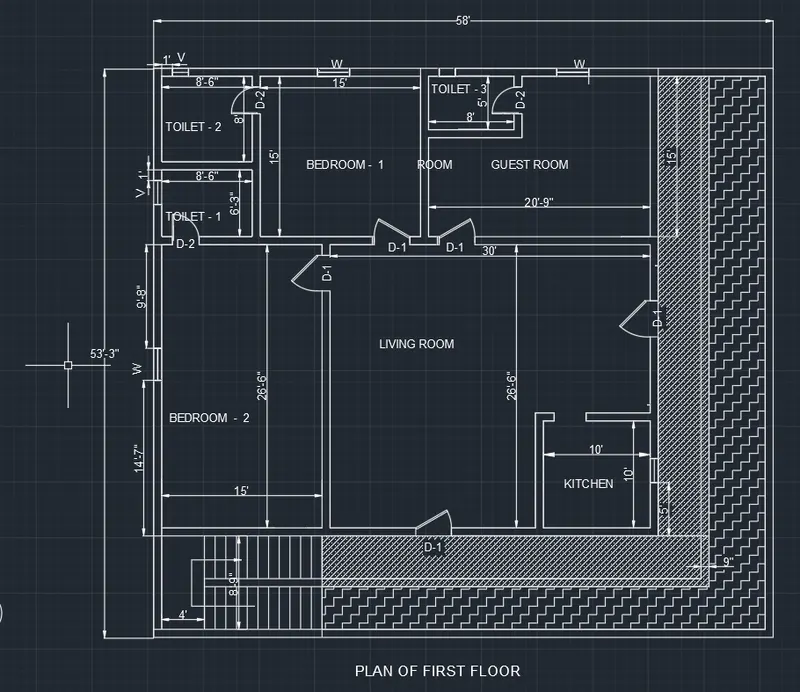
2.Create a rooms like bedrooms,guest,kitchen, toiles and living
- xl> v> specify point
- offset > 9” >select line >specify direction
- The above Offset step is used to create wall thickness for all walls
- Provide openings and remove the lines which are not required by using TRIM command
- Click view tab > goto TOOL PALLET > select door imperial > specify location
- Repeate the above similar steps for window opening
- Assign names for the doors, window and ventilation
- Provide dimension wherever is necessary by using DIMENSION LINEAR command
- Apply HATCH for necessary areas
3.TO CREATE A 3D MODULE WITH REFRANCE TO PLAN AND SECTION:
COMMANDS USED :
- REGION
- BOUNDARY
- 3DORBIT
- UCS
- DYNAMIC INPUT
- EXTRUDE
- SOLID EDIT
- UNION
- SUBTRACT
- SLICE
- ALIGN
- LIGHTS
- RMAT
- RR
- 3D ROTATE
- VIEW
- Turn on the wall layer
- Set the view in any isometric direction
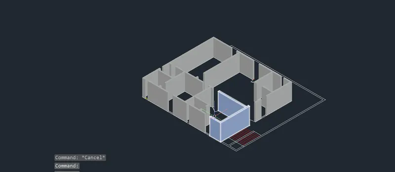
A)Create a region for the walls
- Boundary >pick points >specify wall areas > select region from the options > select OK
- Extrude the walls upto 10’
- Extrude > select the region to extrude > specify length :10’
B)Create the group of section A-A
- Group > select the entire section A-A > enter
C)Align the section with reference of plan
- Align > select object: select the group > specify the point refrances 1,2&3 > enter
- Ungroup >select the group section A-A to ungroup
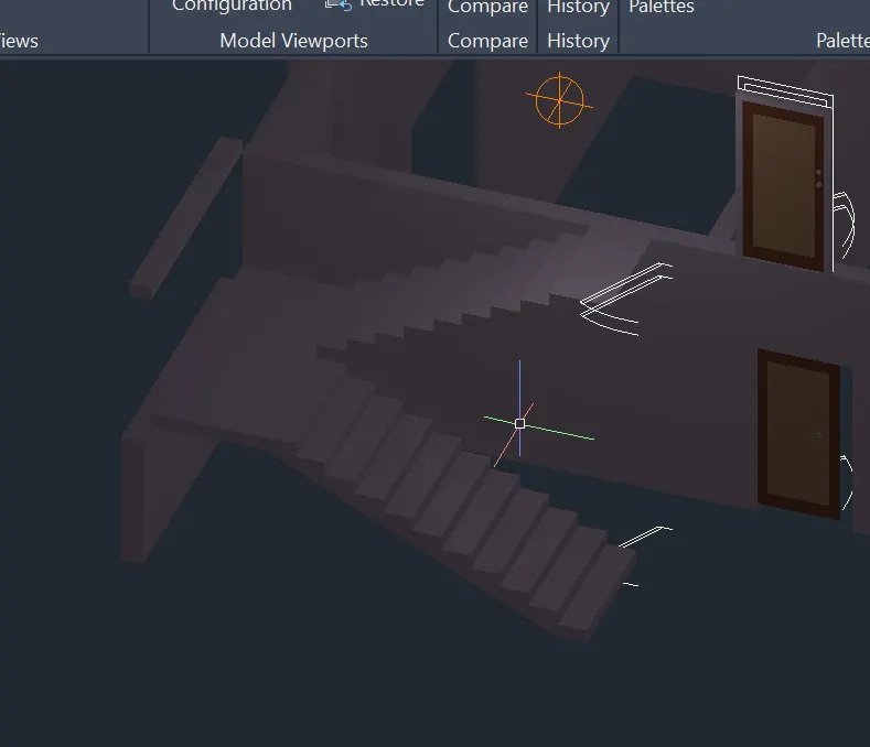
- Region> select the stair case to region > enter
D)Create a stair case
- Extrude > select staircase region > specify distance :4’
- Repeat the above extrude step for stair case landing.
4.Creating windows ,doors , ventilators
- Region the area of frame, mullion, glass of door
- Subtract > select the frame region> select the mullion region > enter.
- Repeat the same procedure for glass
- Extrude > select the frame region > specify the distance :3”
- Extrude > select the mullion region > specify the distance :2”
- Extrude > select the glass region > specify the distance :0.5”
- Specify the colour for all three materials in properties
- Repeats for doors and ventilators
5.Creating a slab
- Create the slab with thickness
- UCS > face >select the top face of wall
- Create rectangle with current UCS
- Extrude > select rectangle >enter height :6”
- Create gallery of first floor
- Solid edit > face> extrude > select the slab face > enter the distance : 4’-9”
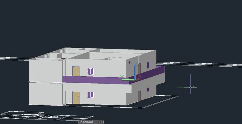
- repeat the same step for another side of the gallery
- Remove unnecessary parts by using SLICE
- Copy the ground floor module with reference point to create first floor.
- Create the parapet walls for 3’
6.Assign the materials
- RMAT > choose the category: wall covering > select walls > right click> assign material to selected object
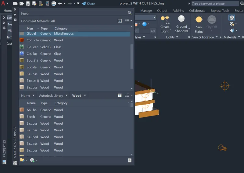
- Repeate RMAT command for door, windows and stair case materials
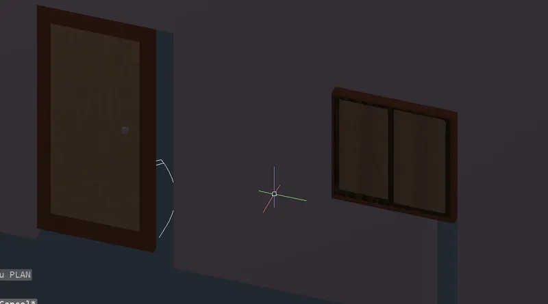
7.Create lights
- Select light > specify points of light or create a solid object at specific height > assign lights
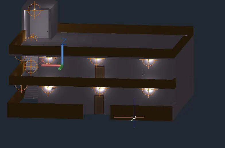
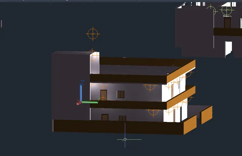
- Select RR command for rendering.
- set render level > 3
- Result: