Project 2_Creating a 3D rendered model for a Residential Building in AutoCad
3D MODEL OF THE RESIDENTIAL BUILDING
Aim: To create a 3D rendered model for a residential building in the AutoCAD.
Introduction:
3D modeling refers to the process of creating a mathematical representation of a 3-dimensional object or shape. This is done using software. 3D models are now widely used in a variety of industries. Motion pictures, video games, architecture, construction, product development, medical, all these industries are using 3D models for visualizing, simulating and rendering graphic designs. 3D modeling in construction is widely gaining popularity due to the plethora of benefits it offers.
Types of 3D modeling
The common types of 3D modeling include simple polygons, 3-D primitives – simple polygon-based shapes, such as pyramids, cubes, spheres, cylinders and cones, spline curves and NURBS (non-uniform rational b-spline) – smooth shapes defined by bezel curves. These are relatively complex, computationally.
3D modeling in construction
Technological advancements are making every task easier and better. We are now able to do more with less in almost every sphere of our lives. Every sector is riding the technology bandwagon for better outcomes and the construction industry follows suit. Be it BIM or 3D modeling, technology is enabling the construction industry to achieve more in lesser time with reduced cost. 3D modeling is changing the presentation world of architectural designs. 3D modeling is enabling architects and designers to be more creative and experimental.
With technologies like reality modeling getting intrinsically weaved into the construction lifecycle, the construction process no longer involves rolling out blueprints of building designs. Construction has largely gone digital. Architectural presentations have moved from draft tables to desktops and tablets.
The adoption of 3D modeling in construction has brought in numerous benefits. 3D or reality modeling, not only speeds up the design process but also enables architects and designers play around with different ideas and identify potential design problems before they become actual issues. 3D modeling in construction, by putting all the pieces together, provides a real-view of the finished project. Amazingly! 3D modeling brings a project to life without even moving a single speck of dust!
3D modeling in construction also allows animation. Naturally, the client can visualize so much more about an upcoming project that a flat drawing could ever provide. Clients can literally have a virtual walkthrough of the proposed building. Just like a 3D movie, a 3D model enables the client to get a feel of how things will be laid out. They can walk through the entry of their future home, reach the lobby and even visualize guests having dinner at the dining area. They can see all this even before a brick has been laid out!
With 3D modeling, it also becomes easy to understand a structure in the context of the surrounding space. Transforming a building into a dream home by virtually surrounding it with lush landscaping is the power 3D modeling provides to an architect or designer. 3D architectural modeling provides a degree of realism that 2D images don’t. Using 3D modeling one can even visualize the texture of the tile that will be put up on a room’s floor. Interesting!
Realistic lighting can be used to demonstrate the warm energy emanating from a kitchen or dining area. It is also possible to fill the space with appropriate furniture and decor choices to understand fully what we have in store.
There is no doubt that use of 3D modeling in construction results in better designing and material utilization. 3D models can be rotated for different perspectives and gather additional views. The advantages of 3D modeling include; checking the errors which might occur in the drawing process, gaining better insight for surface patterns, having virtual tours through walkthroughs, getting renderings with customized interiors, achieving more in lesser cost, enhanced collaboration between teams involved in the construction process.
Commands Used:
Units
Limits
Line
Polyline
Circle
Arc
Rectangle
Trim
Extend
Offset
Mirror
Rectangular Array
Hatch
Move
Rotate
Dimlinear
Dimstyle
Fillet
Linetype
Lineweight
Layers
Mtext
Multileader
UCS
Region
Extrude
Subtract
Box
3Dface
3Dorbit
Hide
Explode
Solid edit
Union
Boundary
3Dmirror
3Drotate
Plan
Render
Procedure:
Creating 2D Architectural Plan
Create the AutoCAD new drawing and set type of unit as Engineering and precision as 0’0”
In insertion scale set unit as Inches.
Create new layers as per requirement
First, draw the plot area of size 60’x20’ with building area using the rectangle and line command with respect to the orientation of site.
Draw a rectangle of dimensions 60’x20’
Provide front side offset of 14’ and all other side offset of 1.5’
And draw the exterior and interior walls for the respective rooms
Draw staircase with the room size of 10.5’ x 6’, the tread is 10” riser is 6.6” in ground floor
Trim the extra lines
Place columns of 9”x18” for the respective positions
Provide the doors and windows for the respective dimensions and trim the extra lines
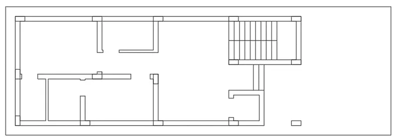
Hatch the necessary area, draw chejja
Indicate the rooms using the single text command.
Provide dimensions for the given floor plan using the dimlinear command.
Using hatch command, dimension command and text command complete the floor plan
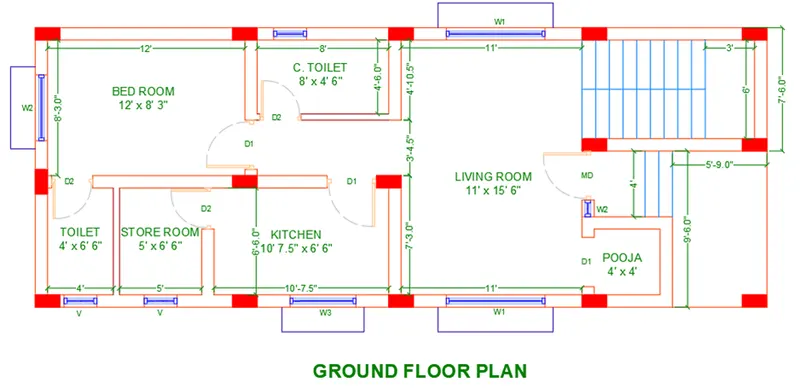
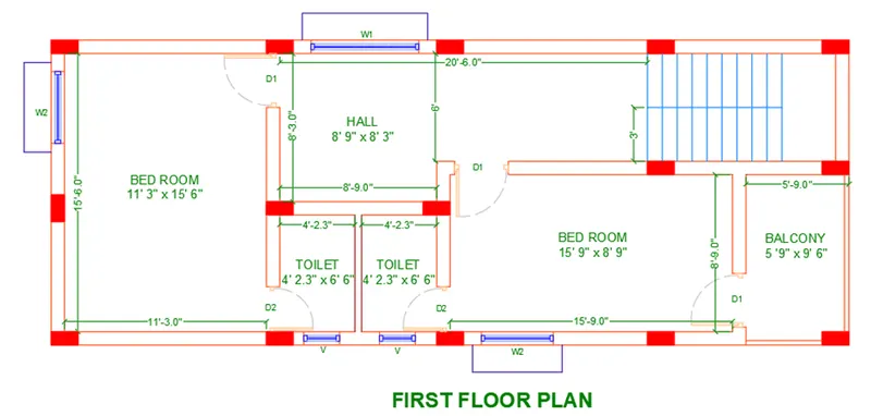
Creating 3D model
To project walls to convert the ground floor plan from AutoCAD 2d to AutoCAD 3D switch the workspace to 3D modelling from the status bar.
Change the view to 3D by clicking on home button of view cube
Set UCS as world
Use Press pull tool to extrude boundaries to total height of 10’
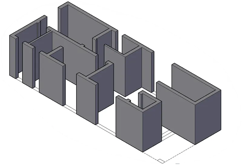
At all the openings like window and doors draw rectangle and use extrude tool to provided required opening.
Select the 2D wireframe and create the rectangle at the windows and doors
Using the REC command rectangle was drawn across all the window portion at the plinth level.
Select all the rectangles just formed and move rectangle and extrude them to create solid till respective sill
Create rectangle again across all the window portion at the plinth level and move them to lintel level then extrude them by 3’ at Lintel level to roof.
By using the union command combine all walls.
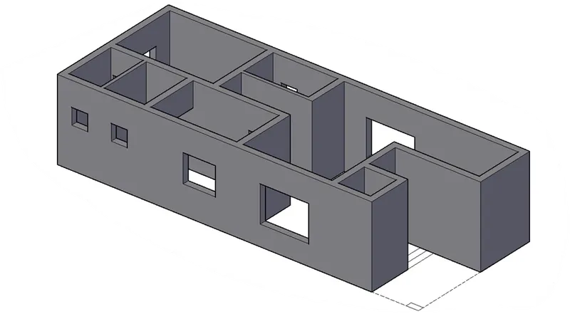
All the main windows openings were provided according to the schedule of windows
Windows
Windows in Living/Dining/Hall are taken as 6’x4’
Windows in all bedrooms are 4’x4’
Windows in Kitchen are taken as 4’x3’ 6”
Ventilators are taken as 2’x2’
Floor
Using the polyline draw lines connecting the outer wall of the building.
Using the extrude command extrude the polyline by 2’ to create the floor.
Create steps by drawing rectangle and extrude them respectively.
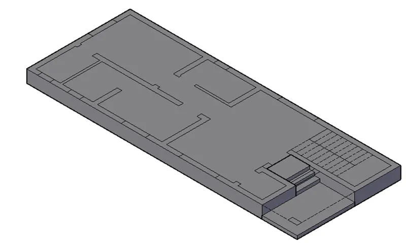
Staircase
Use polyline draw stair tread of 1’ and riser of 6”
Create a region from the side view of the stairs
Provide 3’ landing
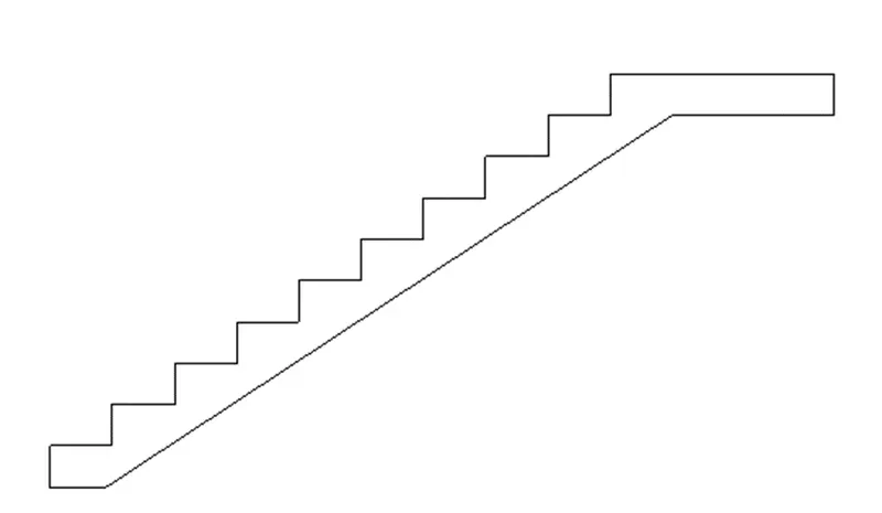
Now extrude the side view to a distance of 3’ as shown in figure
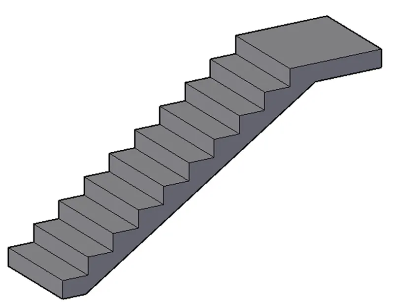
Create another stair flight by following same procedure and use union tool to create single unit
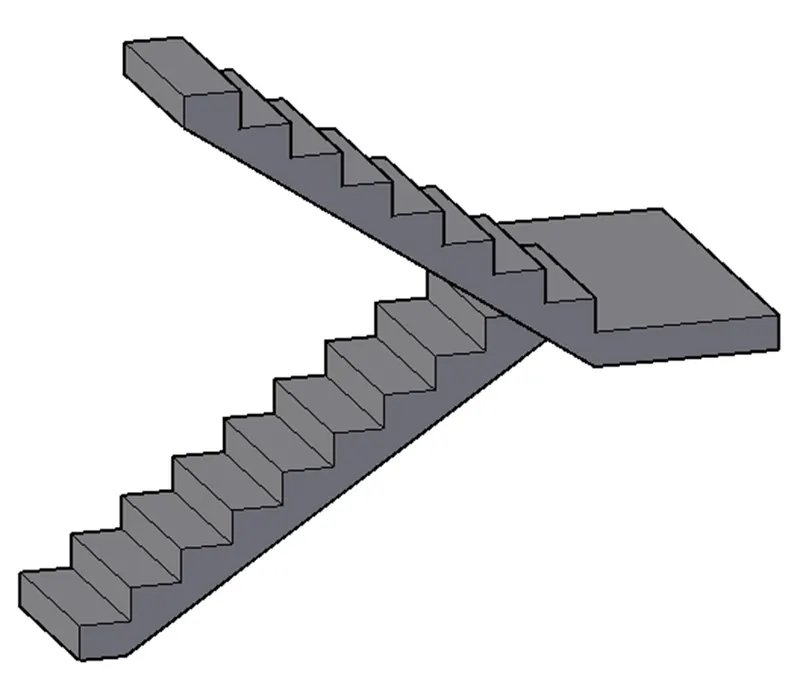
Using the polyline draw lines connecting the outer wall of the building. And don’t include stair area for first floor slab
Using the extrude command extrude the polyline by 6” to create the first floor.
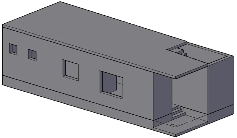
Follow the same procedure and create 3D for first floor plan
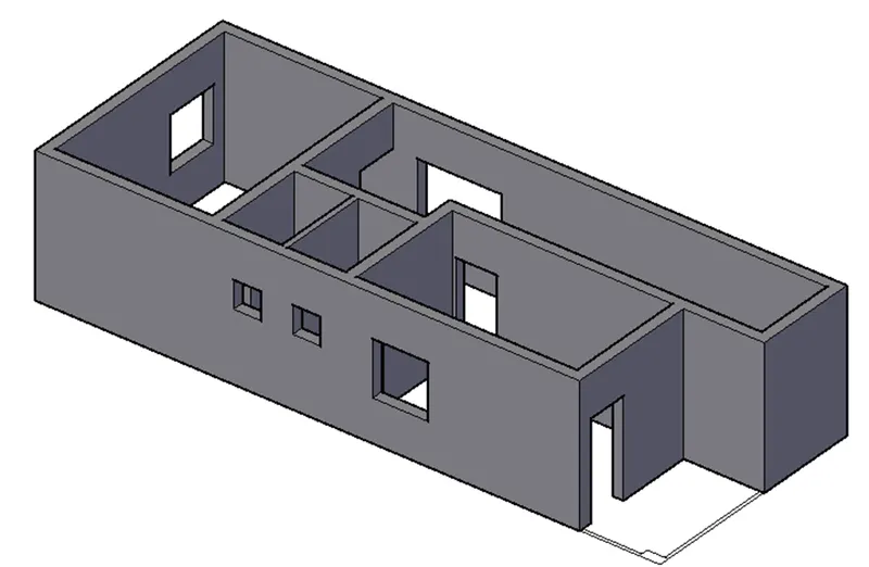
At all the openings like window and doors draw rectangle and use extrude tool to provided required opening.
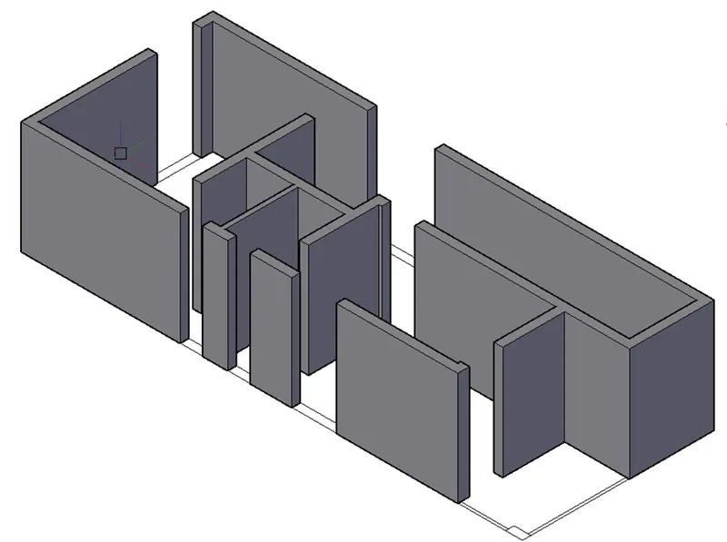
Select the 2D wireframe and create the rectangle at the windows and doors
Using the REC command rectangle was drawn across all the window portion at the plinth level.
Select all the rectangles just formed and move rectangle and extrude them to create solid till respective sill
Create rectangle again across all the window portion at the plinth level and move them to lintel level then extrude them by 3’ at Lintel level to roof.
By using the union command combine all walls.
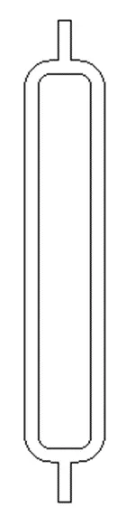
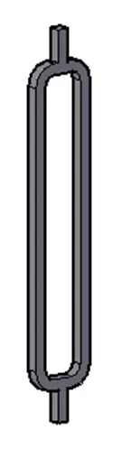
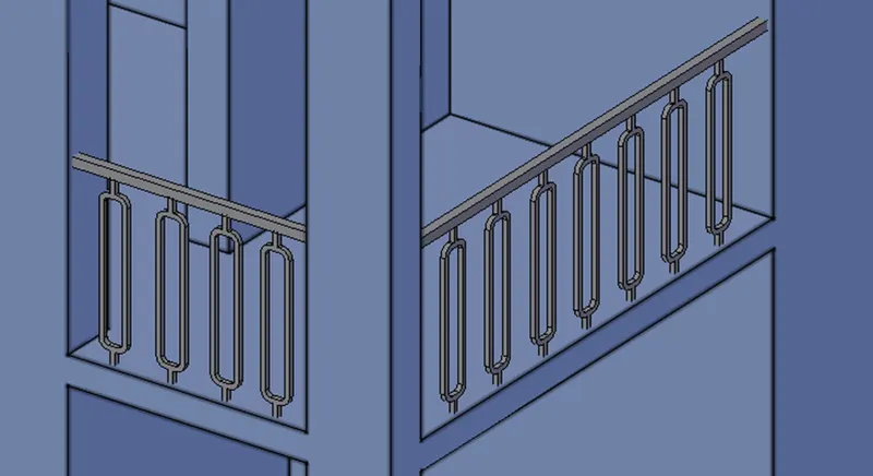
The balcony is provided with railing of the particular design given below
The design is created in using line, fillet and offset tool
Then extrude both and subtract to het the solid shape
Place the shapes along the railing in the balcony
Apply chrome material from the autodesk library
The front parapet wall is designed by subtracting shapes
Draw box and subtract them in parapet
The 3d model was applied with different materials from Autodesk material library respectively for individual parts like railing, doors, windows and parapet etc.
Select the faces carefully and after selecting faces press enter and select the color of our choice and click ok.
Keep repeating this process until completion.
Using the materials library in visualization tab the flooring was also applied.
In the similar manner the corridor, steps and staircase were also applied with materials.
Adjust the texture mapping if it’s not right
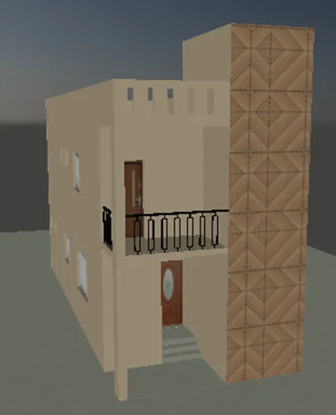
Now place the camera and put it in the required position and then press enter.
Enable sky background and turn on Sun for lighting and shadows
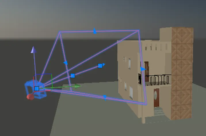
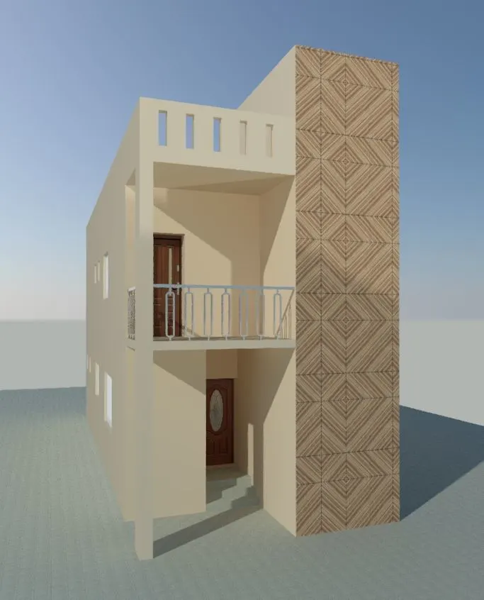
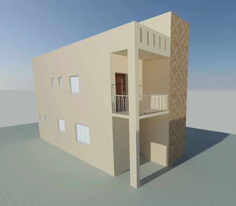
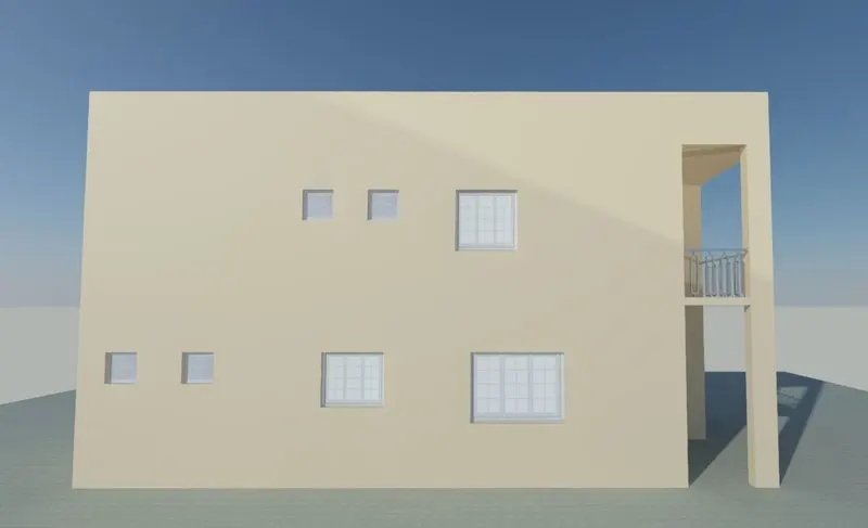
Finally, we select the render option and then slowly it changes to the rendering view as shown in the below figure.
Save the image after completion of rendering
RESULT
The 3D view of a residential building is created and rendered view of the model with materials is attached