Project 2_Creating a 3D rendered model for a Residential Building in AutoCad
AIM: To Create a 3 dimensional model of the residential building with a rendered view.
INTRODUCTION:
- Use of the 2d workspace with commands such as line command, rectangle command, offset command and other drafting tools like trim, move, copy , rotate and such various commands.
- In order to move the 2 dimensional to 3 dimensional, Switching the WSCURRENT( work space setting) from >> STATUS BAR>> 3D modeling>>ok.
- Use of UCS and working with user co-ordinate systems, from command prompt or from status bar, For easy acess of tools in all directions
- Use of various visual style control from QUICK ACESS TOOL BAR such as view port control, view controls and visual styles and view manager.
- Some of the various Sketcing and Drafting tools in 3D modeling are BOX , EXTRUDE , PRESSFULL, SWEEP, LOFT, 3D ROTATE,POLYSOLID, 3D POLY LINE, MIRROR3D, SUBTRACT, UNION, INTERSECT AND UCS manager are the comands which are different some 2D, and can used from RIBBON TAB or from COMMAND PROMPT.
- Use of Layer command, Creating the layers and attcating materials by layers.
- Creataion of RENDERING, rendering which means Assigning materials.
- Creating and Assigning selected material by objects.
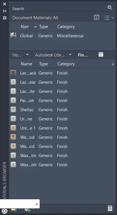
- In order to Browse the material; RIBBON:Render> Material>Materials Browser; TOOL BAR:Render;COMMAND:Mat or MaterialBrowser.
- To define the various ways of Basic Rendering are;TOOL BAR:Render;COMMAND:Render.
- Creating a 3D model of the Residential Building of 2BHK of assumed dimensions.
PROCEDURE:
- First set the units of the sheet of the type Engineering type such as feets and inches.
- Then, set the limits of the sheet as required to the drawing space in the sheet( 0'-0",0'-0';65'-0,74'-5'')assumed values.
- From visual style control>select>Top View>ok, start sketching the plan.
- Sketch the plan with line command of dimensions length 50feets and width 40feets respectively.
- Using Offset commands , provide offset of 9inches for exterior wall and 4inches for interior wall.
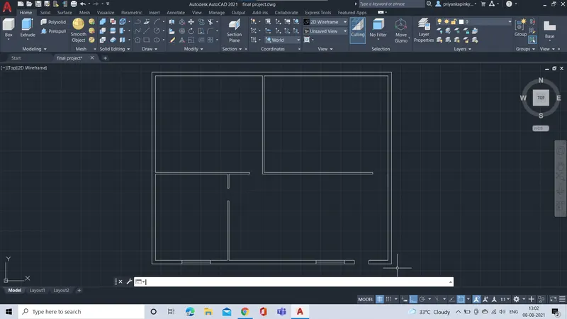
- Using Line command, Create the partian wall in between two rooms.
- Create the elevation plan, using the line command and other drafting tools for creating doors and windows.
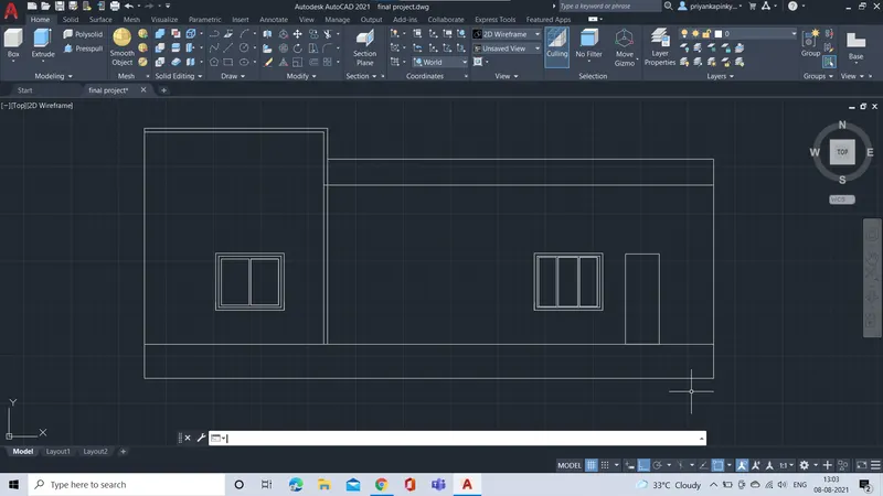
- Provide the plinth of 3feets below the floor level, in the elevation plan.
- Then switch to 3D modelling through working space from status bar.
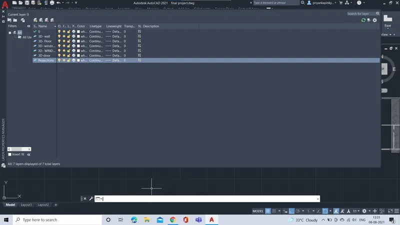
- Create the layers of the drawing from command prompt:LA,create the new layers and name the layers;such as 3D wall, 3D window, 3D Door.. etc;assign different colours for different layers.
- Then copy the plan and elevation to a side, using copy command from Top view.
- Then, using Boundary command>> region>> pick a point>> click on the internal surface>>ok, create the region of the wall in the plan.
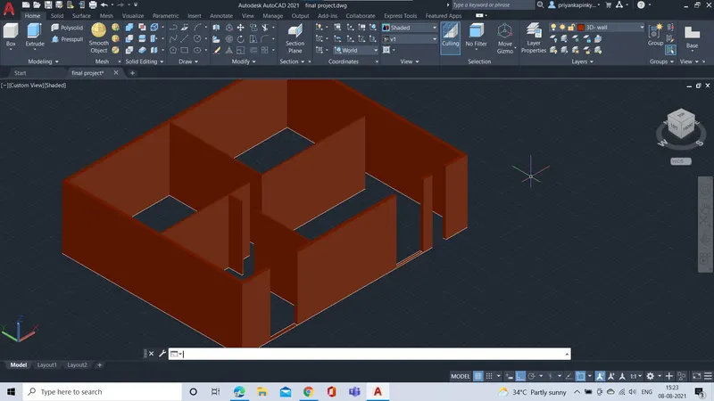
- Using extrude command, Extrude walls to a height of 14 feets in z- axis.
- Then, Create the elevation plan into the Group, from command prompt>Group> select the object(elevation plan)>ok.
- From Isometric ISW, Using rotate command> select the object(elevation plan)>specify the axis line>enter angle as:90>Ok.
- Using the Move command,move the elevation plan to plan of the residential building.
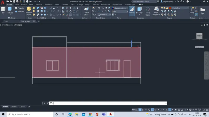
- Then Draft the windows and doors from the copied elevation plan.
- Create window of height 5 feets and length 6 feets with window frame and glass and door of height 7 feets and width 3 feets with door frame and pannel with layers.
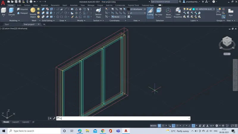
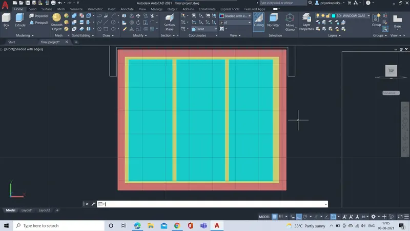
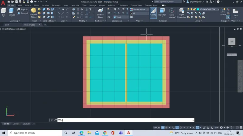
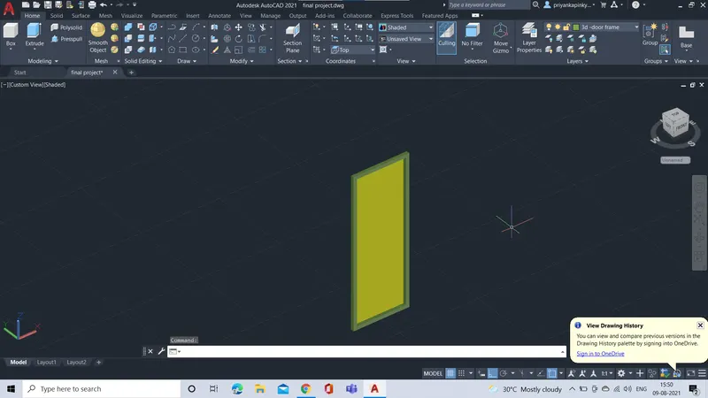
- After creating windows and doors make group both window and door separately.
- Using copy command, copy the window and place in the wall and copy the door and place in the place of door.
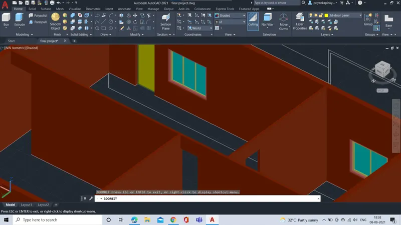
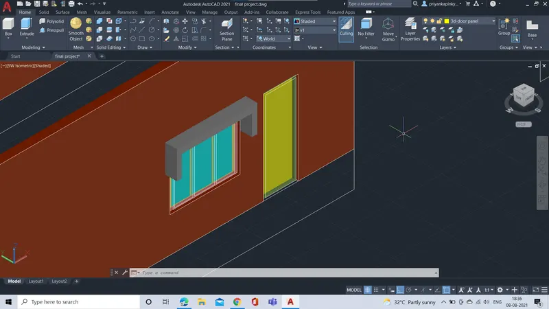
- Then using extrude command fix and place the window and door properly.
- Then,changing the visual style to 2d wire frame,use rectangle command and create the plinth as floor and create the region and extrude with 3 feets below ground level.
- Then,using rectangle command,create the rectangle on the top of the walls as slab, create the as region and extrude with 9inches thickness of the slab.
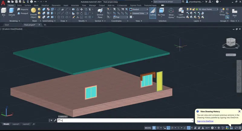
- Then move the slab portion a part from the walls and create the parapet wall of height of 3 feets thickness 9 inches around the wall and replace the slab with parapet wall using move command.
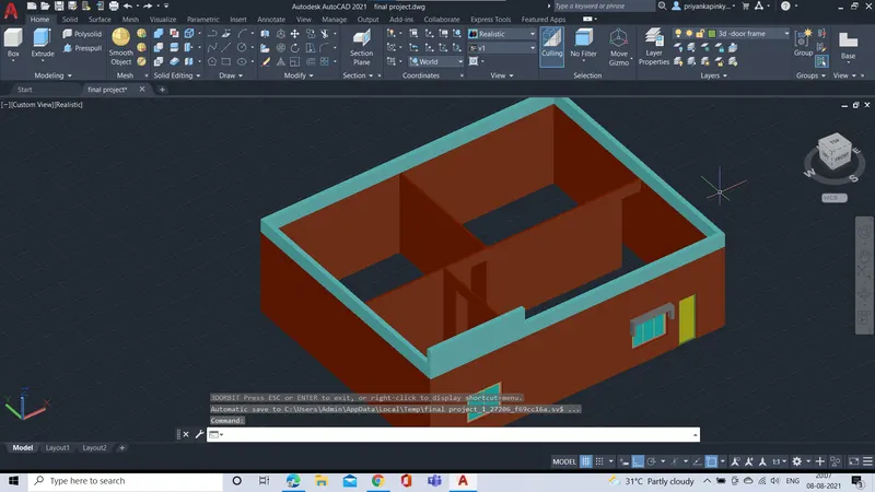
- Later, assign materials to the objects from command prompt: mat,browse from autodesklibrary and select the type and assign the material to the selected object.
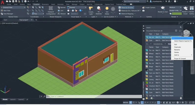
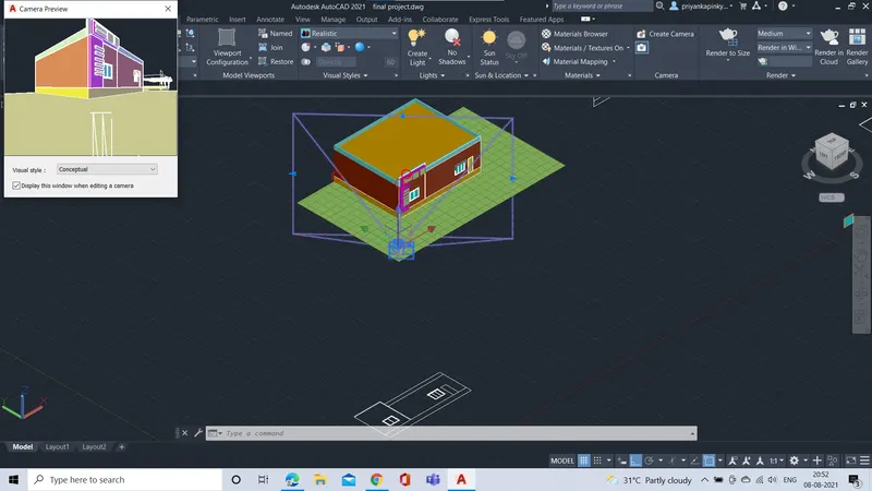
- Then, from visualiazarion tab>create cam>specify:location,height,lens,name,target>>enter>ok.
- Then preview the visual from camera and save the views.
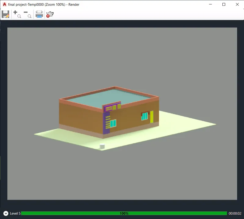
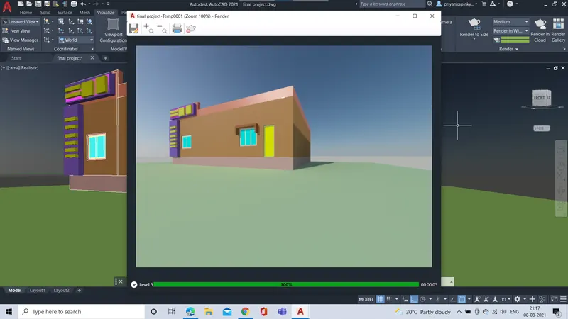
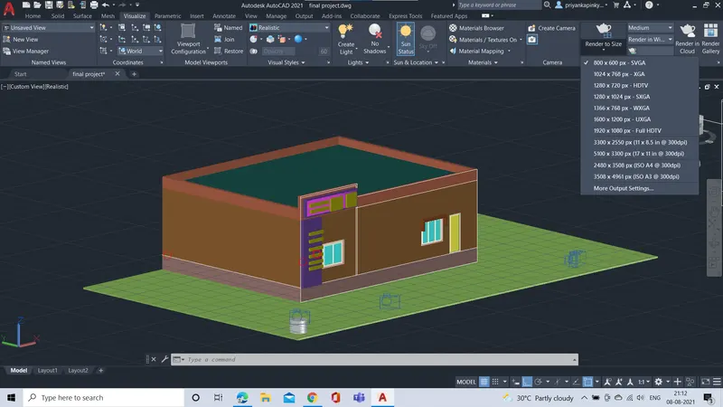
- Finally, create the render of the of the model from saved views and cam or directly, from command prompt:render, and create the render view of the residential model.
RESULT:
Plan and Elevation of the Residential Building
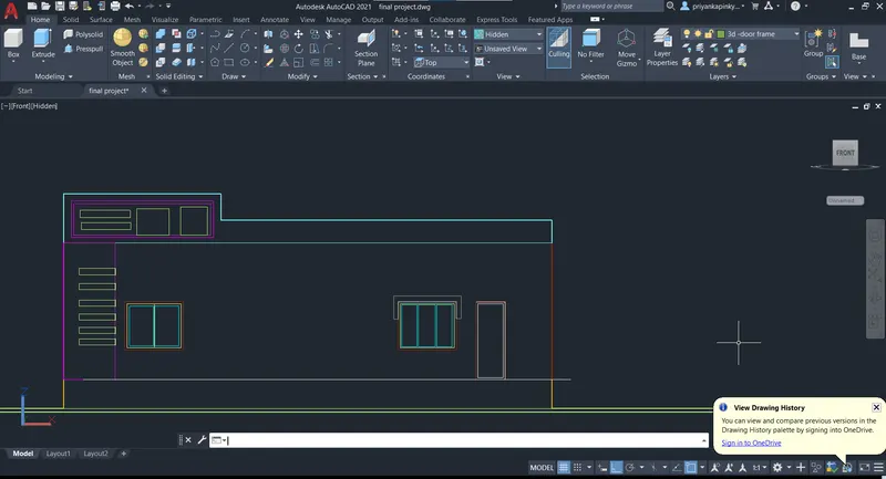
3D model of the residential building before assigning materials.
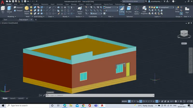
Resiendital Building with Hidden view.
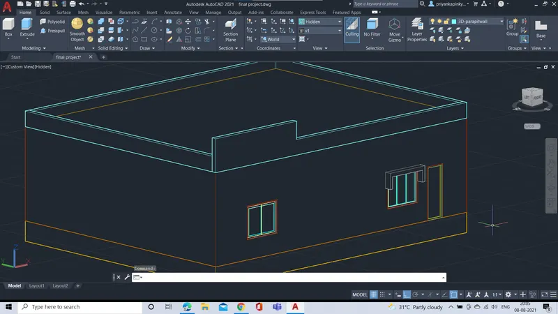
Door and Window in Isometric View.
3D Residential Building in Rendered View