Project 2 Adaptive Cruise Control
EMD BATCH 08
Project 2 Adaptive Cruise Control
Objective of Mini Project:
1. Development of MATLAB Simulink model as per requirement.
- Below is shown our main subsystem which is based on three given requirements. This main subsystem consists of nine inputs and four outputs.
- Inputs are as follows: RadarInput_
LeadVehicle, CameraInput_ LeadVehicle, RadarInput_ DriveVehicle, CameraInput_ DriveVehicle, Time_Gap, Set_ Speed, Set_Gap, CruiseSwitch, SetSwitch. - Outputs are as follows: LeadVehicle_Speed,
DriveVehicle_Speed, LeadVehicle_Detected, Acceleration_Mode.
Requirement 1– Lead Vehicle:
- Requirement-1 consists of two inputs and one output.
- Below is shown the image of same, where CameraInput_LeadVehicle and RadarInput_LeadVehicle are added and give output as LeadVehicle_Speed.
Requirement 2 – Drive Vehicle:
- Requirement-2 consists of three inputs and two outputs.
- Below is shown the image of the same, where CameraInput_DriveVehicle,
RadarInput_DriveVehicle and Acceleration_Mode are added and give output as DriveVehicle_Speed. - Another output LeadVehicle_Detected comes from the signal conversion of input RadarInput_DriveVehicle.
- Here input Acceleration_Mode is feedback through the output of the main subsystem through a unit delay.
Requirement 3 – Adaptive Cruise Control Algorithm:
- Adaptive Cruise Control feature has 3 major modes of operation: OFF Mode, STANDBY Mode & ON Mode. This particular requirement has to be implemented as state machine logic in Simulink.
- The input signals to this state machine system are (Signal Name: Time_Gap, Set_Speed, Set_Gap, CruiseSwitch, SetSwitch).
- Also, the output signals (Signal Name: DriveVehicle_Speed & LeadVehicle_Detected) from requirement-2 is fed back as an input signal into this state machine block.
- Additionally, output signal (Signal Name: LeadVehicle_Speed) from requirement-1 is given as an input signal to this state machine block as well.
- Output from this subsystem is a signal (Signal Name: Acceleration_Mode) which governs the vehicular speed of the drive vehicle which automatically adjusts its speed & velocity to match the lead vehicle.
A. Requirement 3a – ACC OFF MODE state logic:
- This is the default state inside state machine logic. Output signal Acceleration_Mode is at value 0 in this state.
- This state is governed by input signal CruiseSwitch.
- If CruiseSwitch is equal to 1, state ACC STANDBY mode will get activated. If CruiseSwitch is equal to 0, state ACC OFF mode will get activated, from either ACC ON mode or ACC STANDBY mode
Requirement 3b – ACC STANDBY MODE state logic:
- This is the second activated state inside state machine logic. Output signal Acceleration_Mode is at value 1 in this state.
- This state is governed by both input signals CruiseSwitch & SetSwitch.
- If CruiseSwitch is equal to 1, state ACC STANDBY mode will get activated. If CruiseSwitch is equal to 0, state ACC OFF mode will get activated, from either ACC ON mode or ACC STANDBY mode
- If SetSwitch is equal to 1, state ACC ON mode will get activated. If SetSwitch is equal to 0, state ACC STANDBY mode will get activated.
Requirement 3c – ACC ON MODE state logic:
This state will be activated when input signal SetSwitch is equal to 1. There are 6 sub states to this state logic: They are:
- LeadVehicle_Detected_Follow (Default)
- LeadVehicle_Not_Detected
- LeadVehicle_Detected_Resume
- LeadVehicle_Not_Detected_
Resume - LeadVehicle_Speed_lessthan_
Set_Speed - LeadVehicle_Speed_equal_Set_
Speed
2. Requirement Tagging and Traceability report.
A. For Tagging
- Create a word file shown above containing details of all three requirements and save this file in the same folder of your MATLAB model.
- Select the desired requirement in the file shown above and minimise the word file, Right click on subsystem whose tagging is to be done -> Requirements -> Link to selection in Word.
- As we can see above in requirement,Tagging is done for selected subsystem.when we click on that the same word file will open what we created.
- Tagging will be done and by selecting subsystems it will appear with a coloured background shown Above.
B. Traceability Report:-
- On Title bar -> Apps -> Requirements Manager. New window will show up in which Layout -> Requirements browser.
- Image is show below for the above mentioned steps.
- Clicking on the Requirements will colour the respective block background as shown below.
- To generatethe report click on Shrare -> Generate Model Traceability Report.
- Report is shown below.
3. MBD compliant changes, Data Dictionary creation, S function generation and code generation
(a) MBD compliant changes
- Click on Modelling -> Model settings -> Solver
- In solver selection -> Type: Fixed-step and Solver: discrete (no continuous states)
- Under Solver details set Fixed step size: 0.01
- In code generation -> Browse system target file for Embedded coder
- Code generation -> Interface -> Under Software environment Tick mark the "floating-point numbers"
- Apply and OK
(b) Data Dictionary creation
- In simulink model -> modelling -> design -> Link to Data Dictionary
- Window of model properties will pop up -> New -> Create a file name -> Apply OK -> Symbol will appear on the left bottom side shown below.
- Click on External Data and new window will pop up with a file name written on left side, selecting that will show down a object with "Design data"
- To add any signal click on Simulink Signal and for adding any constant click on Simulink Parameter
- Below is shown the list of required signals and parameters to be used in this project.
(c) Creation of S block and code generation.
- To create S block -> Right click on subsystem -> C/C++ code -> Generate S function
- New window will appear -> Tick mark the block of SIL at bottom and then select Build option.
- A model file of S block will be created, which is shown below.
- To generate the code on Title bar -> Apps -> Embedded coder -> Build
- Multiple code will be generated with extension of .c and .h files. Below is shown the list of generated codes
4. Model Advisor
- On Title bar -> Modelling -> Model advisor -> Window with model name will appear Click OK -> New window will appear having options of By product and By Task
- Tick mark the following options shown below and run the model advisor.
- The report generated by this function is supposed to have errors less than 15. To reduce errors, go through the report and solve the possible errors and generate the report again.
5. Result
- Result is shown below with display and scope which is showing active for Straight drive because of the condition selection made inside the logic. These results are dependent on the initial values of signals created in Data dictionary.
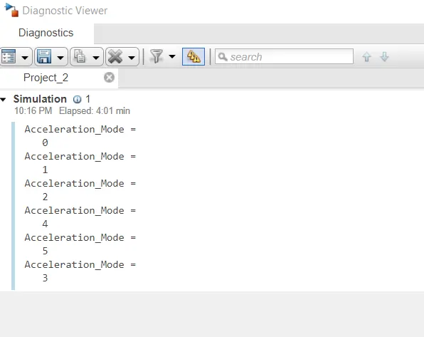
- Acceleration modes are shown in diagnostic viewer.