Project 2 Adaptive Cruise Control
Aim-
The aim of the project is to understand and implement the Adaptive Cruise Control feature model using Model Based Development technique and Generate autocode in Matlab environment by following MAAB guidlines.
Adaptive Cruise Control (ACC)
Adaptive cruise control is an ADAS feature which is resposible for controlling of vehicle and give some comfort to the driver in mainly Highways and countryroads. Adaptive Cruise Control (ACC) mainly uses radar sensors to check the position related information of the Lead vehicle. ACC is resposible to sense and control speed of the drive vehicle according to the lead vehicle, Since Adaptive Cruise Control is a comfort and convenience system, brake interventions and vehicle acceleration only take place within defined limits. Even with Adaptive Cruise Control switched on, it remains the driver’s responsibility to monitor the speed and distance from the vehicle in front.
Radar semsor can be Sensor fused with camera sensor to improve the precision of the measurement and an mathematical model is created to extract the Lead/Drive vehicle speed. these informations are further fed to the controlling alorithm which is modeled using Stateflow technique based on the requirements. This controlling algorithm will pass the Acceleration mode information such that the vehicle speed can be controlled automatically.
In this project we try to model maily the control stretagy using Model Based development environment and by following MAAB guidlines we auto generate "C-code" in the Matlab environment.
Objective of Main Project:
- Developing Adaptive Cruise Control feature as per the Requirement Document using MATLAB Simulink.
- Follow all the MBD related processes: Requirement Tagging & Traceability, SLDD creation, Configuration Parameter changes, Model Advisor check & Code Generation.
- In Configuration Parameters: enable “Support Floating Numbers” under Code Generation settings.
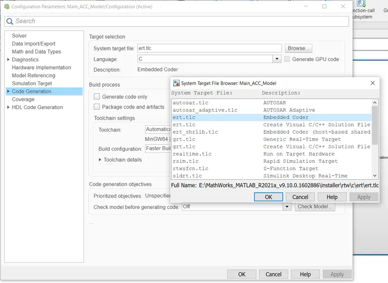
- Use Embedded Coder to generate the code.
- If choosing code generation, Storage class for Input signals: ImportedExtern; Storage class for Output signal: Export to File; Storage class for local signals: localizable; Storage class for calibration signals: Const.
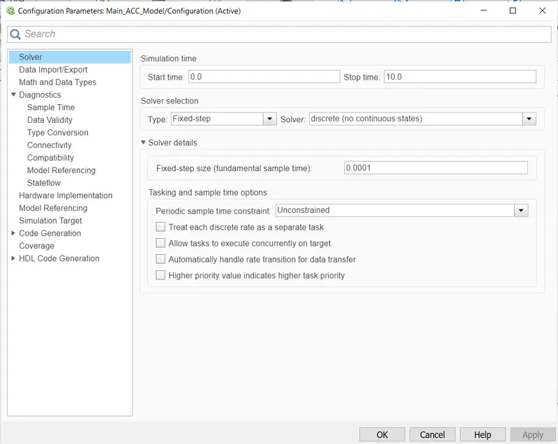
- Choose sample time for all signals as 0.01s
The requirement of the projects are to Link the requirement in the word file and can be Tagged using the Requirements option "Link to selection word". I followed the right procedure to develop the model and for code generation, I followed below steps to achileve the Aim of the project.
Step1- To create subsystem and Give signal names as per requirements. (we'll resolve all signals after creation of SLDD)
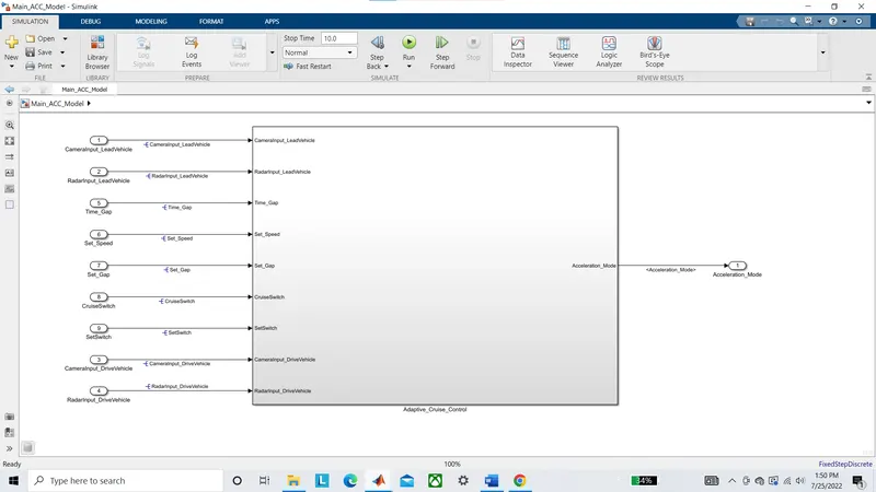
Here is the Input signals required for the ACC purpose....
1. CameraInput_LeadVehicle
2. RadarInput_LeadVehicle
3. CameraInput_DriveVehicle
4. RadarInput_DriveVehicle
5. Time_Gap
6. Set_Speed
7. Set_Gap
8. CruiseSwitch
9. SetSwitch
and the output of the subsystem is
1. Acceleration_Mode
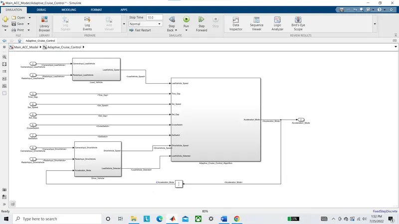
Now look under the main subsystem we have three subsystems for implementing three Requirement from the Requirement document namely...
1. Lead_Vehicle
2. Drive_Vehicle
3. Adaptive_Cruise_Control_Algorithm
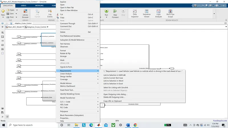
Step2- Link the subsytems by selecting text in the word file (requirement document).{MainProject.doc}
Step3- Now we implement the logic for the Requiement 1.
Requirement 1– Lead Vehicle:
- Lead Vehicle is a vehicle which is driving in the road ahead of our drive vehicle. Two input signals (Signal Name: CameraInput_LeadVehicle & RadarInput_LeadVehicle).
- Ideally sensor fusion techniques will be deployed to process & analyze data from camera & radar. For complexity reasons, let’s not adapt to any such algorithms.
- We can simply add both the radar & camera inputs & the corresponding output is read as Speed profile output (Signal Name: LeadVehicle_Speed).
- Speed data of the lead vehicle is critical in implementing the Adaptive Cruise Control algorithm.
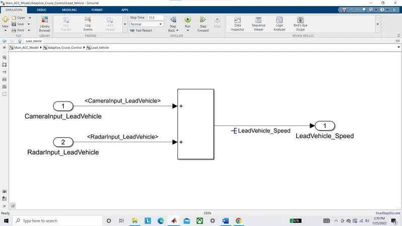
In this requirement we take two inputs to detect the lead vehicle mainly camera and Radar inputs and for complexity reasons we will replace the computationaal algorithm of vehicle speed detection with a simple add block. The output of the subsytem gives the Lead vehicle speed.
Step4- Now we implement the logic for the Requiement 2.
Requirement 2 – Drive Vehicle:
- Drive Vehicle is the vehicle driven by the user & this is the vehicle which has ACC algorithm in it.
- Like the Lead Vehicle, Drive Vehicle algorithm also has 2 input signals (Signal Name: CameraInput_DriveVehicle, RadarInput_DriveVehicle) & one signal coming as an Input to this subsystem (Signal Name: Acceleration_Mode) – three inputs into this requirement in total.
- Like the above requirement, sensor fusion techniques will also be deployed here, for complexity reasons we are ignoring them.
- Two output signals come from this subsystem (Signal Name: DriveVehicle_Speed & LeadVehicle_Detected).
- Signal DriveVehicle_Speed is summation of three input signals mentioned above & LeadVehicle_Detected is renamed from Input Signal RadarInput_DriveVehicle by mere use of Signal Conversion block.
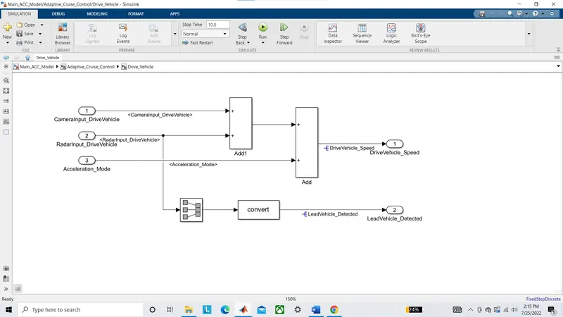
In this subsystem I added all three inputs ie. camera input and Radar input and Acceleration mode to calculate Drive vehicle speed. although it is not the same as the original algorithm but due to complexity reasons and as per requirement we simply add all three input signals to calculate drive vehicle speed and use signal converter block to convert the Radar input to the lead vehicle detected.
Step5- Now we implement the logic for the Requiement 3.
Requirement 3 – Adaptive Cruise Control Algorithm:
- Adaptive Cruise Control feature has 3 major modes of operation: OFF Mode, STANDBY Mode & ON Mode. This particular requirement has to be implemented as state machine logic in Simulink.
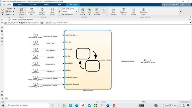
- The input signals to this state machine system are (Signal Name: Time_Gap, Set_Speed, Set_Gap, CruiseSwitch, SetSwitch).
- Also, the output signals (Signal Name: DriveVehicle_Speed & LeadVehicle_Detected) from requirement-2 is fed back as an input signal into this state machine block.
- Additionally, output signal (Signal Name: LeadVehicle_Speed) from requirement-1 is given as an input signal to this state machine block as well.
- Output from this subsystem is a signal (Signal Name: Acceleration_Mode) which governs the vehicular speed of the drive vehicle which automatically adjusts its speed & velocity to match the lead vehicle.
Requirement 3a – ACC OFF MODE state logic:
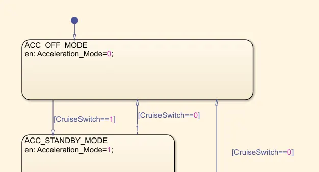
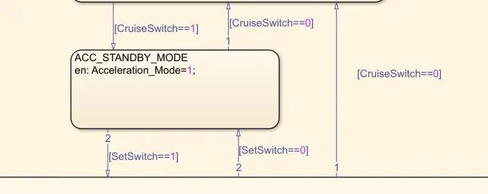
- This is the default state inside state machine logic. Output signal Acceleration_Mode is at value 0 in this state.
- This state is governed by input signal CruiseSwitch.
- If CruiseSwitch is equal to 1, state ACC STANDBY mode will get activated. If CruiseSwitch is equal to 0, state ACC OFF mode will get activated, from either ACC ON mode or ACC STANDBY mode
Requirement 3b – ACC STANDBY MODE state logic:
- This is the second activated state inside state machine logic. Output signal Acceleration_Mode is at value 1 in this state.
- This state is governed by both input signals CruiseSwitch & SetSwitch.
- If CruiseSwitch is equal to 1, state ACC STANDBY mode will get activated. If CruiseSwitch is equal to 0, state ACC OFF mode will get activated, from either ACC ON mode or ACC STANDBY mode
- If SetSwitch is equal to 1, state ACC ON mode will get activated. If SetSwitch is equal to 0, state ACC STANDBY mode will get activated.
Requirement 3c – ACC ON MODE state logic:
This state will be activated when input signal SetSwitch is equal to 1. There are 6 sub states to this state logic: They are:
- LeadVehicle_Detected_Follow (Default)
- LeadVehicle_Not_Detected
- LeadVehicle_Detected_Resume
- LeadVehicle_Not_Detected_Resume
- LeadVehicle_Speed_lessthan_Set_Speed
- LeadVehicle_Speed_equal_Set_Speed

Requirement 3c (i) – LeadVehicle_Detected_Follow (ACC ON MODE):
- This is the default sub state inside ACC ON MODE state. Output signal Acceleration_Mode is equal to 2.
- Condition to transit from LeadVehicle_Detected_Follow to LeadVehicle_Not_Detected; Input signal condition LeadVehicle_Detected == 0.
- Condition to transit from LeadVehicle_Detected_Follow to LeadVehicle_Speed_lessthan_Set_Speed; Input Signals condition (LeadVehicle_Detected == 1) && (LeadVehicle_Speed < Set_Speed) || (Time_Gap < Set_Gap).
Requirement 3c (ii) – LeadVehicle_Not_Detected (ACC ON MODE):
- Output signal Acceleration_Mode is equal to 1.
- Condition to transit from LeadVehicle_Not_Detected to LeadVehicle_Detected_Follow; Input signals condition [(LeadVehicle_Detected==1) && (DriveVehicle_Speed == Set_Speed) && (LeadVehicle_Speed >= Set_Speed) && (Time_Gap >= Set_Gap)]
- Condition to transit from LeadVehicle_Not_Detected to LeadVehicle_Speed_lessthan_Set_Speed; Input signals condition [(LeadVehicle_Detected == 1) && (LeadVehicle_Speed < Set_Speed) || (Time_Gap < Set_Gap)]
Requirement 3c (iii) – LeadVehicle_Detected_Resume (ACC ON MODE):
- Output signal Acceleration_Mode is equal to 3.
- Condition to transit from LeadVehicle_Detected_Resume to LeadVehicle_Detected_Follow; Input signals condition [(DriveVehicle_Speed == Set_Speed) && (LeadVehicle_Speed >= Set_Speed) && (Time_Gap >= Set_Gap)]
- Condition to transit from LeadVehicle_Detected_Resume to LeadVehicle_Not_Detected_Resume; Input signal condition LeadVehicle_Detected==0.
- Condition to transit from LeadVehicle_Detected_Resume to LeadVehicle_Speed_equal_Set_Speed; Input Signal condition [(DriveVehicle_Speed < Set_Speed) && (LeadVehicle_Speed > DriveVehicle_Speed) && (Time_Gap >= Set_Gap)]
Requirement 3c (iv) - LeadVehicle_Not_Detected_Resume (ACC ON MODE):
- Output signal Acceleration_Mode is equal to 1.
Requirement 3c (v) - LeadVehicle_Speed_lessthan_Set_Speed (ACC ON MODE):
- Output signal Acceleration_Mode is equal to 4.
- Condition to transit from LeadVehicle_Speed_lessthan_Set_Speed to LeadVehicle_Not_Detected; Input signal condition [(LeadVehicle_Detected == 0) && (DriveVehicle_Speed == Set_Speed)]
- Condition to transit from LeadVehicle_Speed_lessthan_Set_Speed to LeadVehicle_Speed_equal_Set_Speed; Input signals condition [((LeadVehicle_Speed*1.25>=DriveVehicle_Speed) && (LeadVehicle_Speed * 0.75<=DriveVehicle_Speed)) && (DriveVehicle_Speed < Set_Speed) && ((Time_Gap<=1.25*Set_Gap) && (Time_Gap >=0.75*Set_Gap))]
Requirement 3c (vi) - LeadVehicle_Speed_equal_Set_Speed (ACC ON MODE):
- Output signal Acceleration_Mode is equal to 5.
- Condition to transit from LeadVehicle_Speed_equal_Set_Speed to LeadVehicle_Not_Detected_Resume; Input signal conditions is [(LeadVehicle_Detected == 0) || (DriveVehicle_Speed <= Set_Speed)]
- Condition to transit from LeadVehicle_Speed_equal_Set_Speed to LeadVehicle_Detected_Resume; Input signal conditions [(DriveVehicle_Speed < Set_Speed) && (LeadVehicle_Speed > DriveVehicle_Speed) || (Time_Gap >= Set_Gap)]
- Condition to transit from LeadVehicle_Speed_equal_Set_Speed to LeadVehicle_Speed_lessthan_Set_Speed; Input signals conditions [(LeadVehicle_Speed
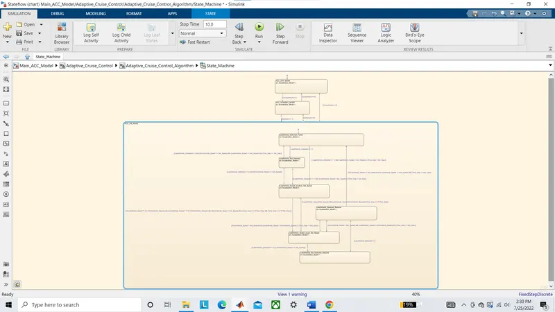
In this requirement we implement a state machine exactly as per the requirement given above and take output as Acceleration_Mode this chart logic is then consider as the main control algorithm for the ACC operation.
Step6- Make SLDD by creating new DD in the model property. then add all variables and signals and parameters according to the data given in the requirement and save the changes.
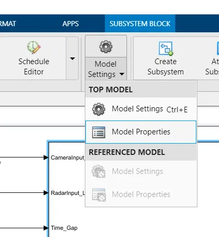
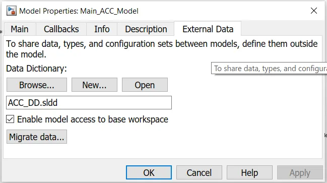
For the output variables define the header file and main source file to save the data related to the variables when the code generation is executed.(ACC_func.h, ACC_func_RAM.c)
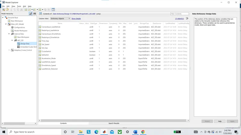
Step7- Now try to modify the configuration parameters from the model setting as per MAAB guidlines (basic functional details which totally depends on the engineers experience).
we uses embedded coder for generating code in this project.
Step8- After manually updating model setting we go for rechecks all the required configuration using model advisor tests. Go to the Model Advisor tool and select the model and run tests for "Modeling Standards for MAB" under By Task tests.
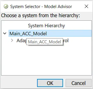
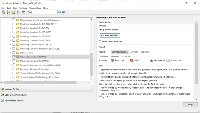
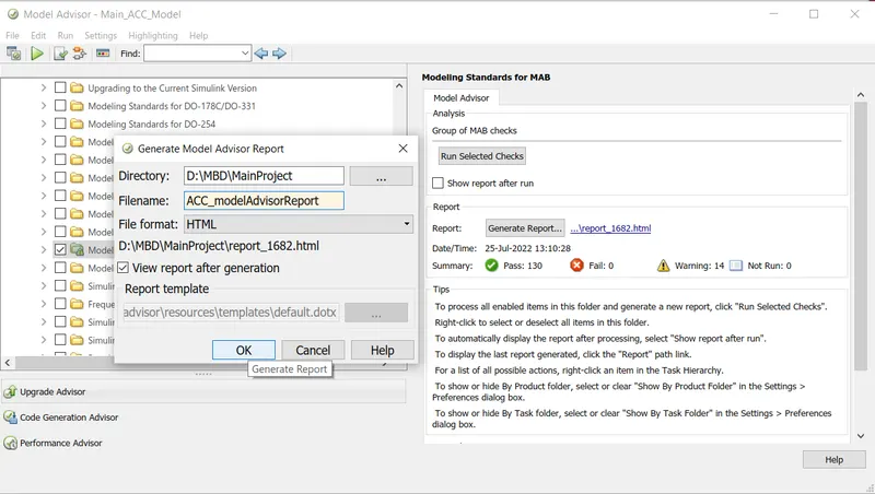
Now try to remove all the errors and reduce the warning to less than 15 (14 in my case) and save the test report at the same folder where the main model is saved.
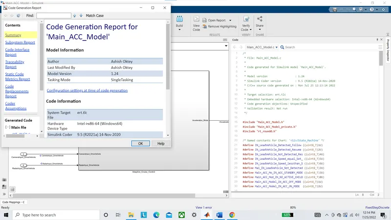
Step9- Now try to update model by {Ctrl+D} and after successful compilation we go for code generation by clicking {Ctrl+B}. The model files and supprting SLDD header files are saved in the current directory automatically and Code generation report will be generated.