Adaptive Cruise Control
Aim: To Develop The Model for Adaptive Cruise Control System for Changing its Modes Based on Lead Vehicle Speed , Drive Vehicle Speed and Operation Set by Driver with the use of Simulink.
Objective:
- To develop the model as per the requirement.
- To Generate the C code from the model.
Introduction:
Adaptive Cruise Control(ACC) system is one of the Advanced Driver Assistance Features which slows down or speed up the vehicle automatically to keep in the pace with the vehicle infornt of it. Adaptive Cruise control system is also known as Radar Cruise Control , Intelligence Cruise Control , Autonomous Cruise Control etc.The driver sets the maximum speed , than a radar sensor which is mounted either under the bumper or at front grille looks up the traffic infront of the driver car and adjust the speed and gap(distance or time ) based on the front vehicle. If front vehicle is not detected it works like a cruise control system. If there is front vehicle than it adjust the speed of the driver vehicle accordingly. So it called as apdative cruise control. ACC is the cruical system for autonomous /self driving vehicle which helps to maintain the distance and speed based on the front vehicle.Figure 1 shows the typical illustration seen on the dashboard of a vehicle which have the adaptive cruise control system.
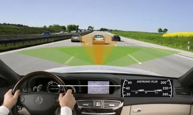
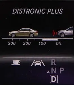
Figure 1: Adaptive Cruise Control System
In this project , the adaptive cruise control model is develop which have three main modes which are:
- ACC OFF
- Stand By
- ACC ON
ACC OFF mode is the default mode for the vehicle. When the driver presses/activate the cruise switch than the model is change to Stand By mode. If driver set the speed and time gap than ACC On mode is activated. Further ACC ON Mode have 6 different Modes which are as follow:
- Lead Vehicle Detected Follow(Default Mode)
- Lead Vehicle Not Detected
- Lead Vehicle Detected Resume
- Lead Vehicle Not Detected Resume
- Lead Vehicle Speed less than Set Speed
- Lead Vehicle Speed is equal to Set Speed
List of Signal:
| Signal Name | Type | Data Type | Dimension | Minimum Value | Maximum Value |
| CameraInput_LeadVehicle | Input | Uint8 | 1 | 0 | 255 |
| RadarInput_LeadVehicle | Input | uint8 | 1 | 0 | 255 |
| CameraInput_DriveVehicle | Input | uint8 | 1 | 0 | 255 |
| RadarInput_DriveVehicle | Input | uint8 | 1 | 0 | 255 |
| Time_Gap | Input | uint8 | 1 | 0 | 255 |
| Set_Speed | Input | uint8 | 1 | 0 | 255 |
| CruiseSwitch | Input | boolean | 1 | 0 | 1 |
| SetSwitch | Input | boolean | 1 | 0 | 1 |
| Accleration_Mode | Output | uint8 | 1 | 0 | 255 |
| LeadVehicle_Speed | Output | uint8 | 1 | 0 | 255 |
| DriveVehicle_Speed | Output | uint8 | 1 | 0 | 255 |
| LeadVehicle_Detected | Output | uint8 | 1 | 0 | 255 |
Simulink Model As Per the Requirement.
a. Requirement 1: Lead Vehicle
It has 2 input signal which is CameraInput_LeadVehicle and RadarInput_LeadVehicle.Output signal from the subsystem is the LeadVehicle_Speed. The LeadVehicle_Speed is the summation of CameraInput_LeadVehicle and RadarInput_LeadVehicle.Figure 2 shows the simulink model for Lead vehicle subsytem.
LeadVehicle_Speed=CameraInput_LeadVehicle+RadarInput_LeadVehicle
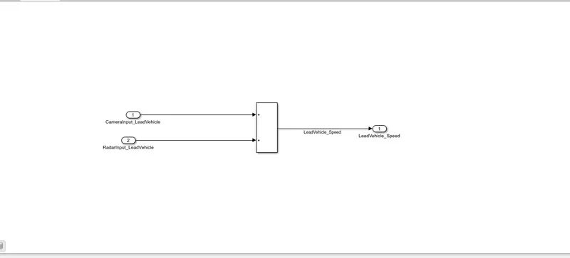
Figure 2: Simulink Model arrangement for Requirement 1 i.e Lead Vehicle
b.Requirement 2: Drive Vehicle
It has 3 input Signal i.e CameraInput_DriveVehicle ,RadarInput_DriveVehicle and Accleration_Mode. It has 2 output signal which are DriveVehicle_Speed and LeadVehicle_Detected. DriveVehicle_Speed is the summation of all the above mentioned input signal while the LeadVehicle_Detected is the signal conversion of RadarInput_DriveVehicle.Figure 3 shows the simulink block arrangement for Requirement 2.
DriveVehicle_Speed=CameraInput_DriveVehicle+RadarInput_DriveVehicle+Accleration_Mode
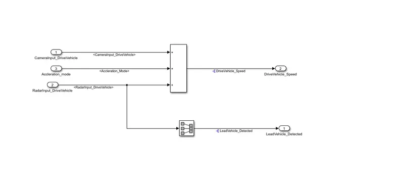
Figure 3: Simulink Block Arrangement for Requirement 2 i.e. Drive Vehicle.
c.Requirement 3: Cruise Control Main Algorithm
Cruise control control algorithm subsystem have 3 features which is ACC OFF Stand By and ACC ON Mode. It has 8 input signal and one output signal. Input signals are Time_Gap, Set_Gap, Cruise_Switch,Set_Switch,LeadVehicle_Speed,DriveVehicle_Speed,LeadVehicle_Detected and Set_Speed.And the output from the subsystem is the Accleration_mode. The transition from the one mode to another mode can be implemented by the concept of state machine.Figure 4 shows the Cruise control main algorithm by the concept of state machine.The transition from one mode to another is discussed further.
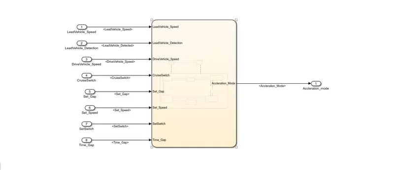
Figure 4: Adaptive Cruise Control Mode Change Main Alogorithm
Condition for Transition From one Mode to Another Mode
1. ACC OFF
ACC OFF mode is the default mode where the Accleration_Mode output will be 0.
Output: Accleration_Mode=1
2. STAND BY
The system will go to the Stand By mode when the value of CruiseSwitch is equal to 1 and which gives the the value for Accleration_mode to be 1. If the CruiseSwitch is 0 than again the system will return to ACC OFF mode. When the SetSwitch is equal to one than the system will goes to ACC ON mode.
Condition:
ACC OFF `->`STAND BY
CruiseSwitch=1, and the Output i.e Accleration_Mode=1
STAND BY `->`ACC OFF
CruiseSwitch=0 and output i.e. Accleration Mode=0
STAND BY `->` ACC ON
SetSwitch=1, and output depend on the condition of ACC ON mode
ACC ON `->` STAND BY
SetSwitch=0,Output,i.e Accleration_Mode=1.
3. ACC ON
ACC ON mode contains 6 substate and the Accleration_Mode for th different states is shown in the Table 2. In ACC ON Mode, Lead Vehicle Detected Follow is the default mode.The transition from the default mode happens as per the input provided to the system.
Table 2: Accleration_Mode for different Substates in the ACC ON Mode
| States | Accleration_Mode |
| Lead Vehicle Detected Follow | 2 |
| Lead Vehicle Not Detected | 1 |
| Lead Vehicle Detected Resume | 3 |
| Lead Vehicle Not Detected Resume | 1 |
| Lead Vehicle Speed Less than Set Speed | 4 |
| Lead Vehicle Speed is equal to Set Speed | 5 |
Condition:
ACC ON`->`STAND BY
SetSwitch=0, Output,i.e Accleration_Mode=1.
ACC ON`->`ACC OFF
CruiseSwitch=0, Output i.e Accleration_Mode=0.
Condition for transition of Substates
The Value of Accleration_Mode is given in the table and based on the state of the system, the value of Accleration_Mode changes.
3.1 LeadVehicle_Detected_Follow:
Transition:
a) LeadVehicle_Detected_Follow`->`LeadVehicle_Not_Detected
Condn:
LeadVehicle_Detection=0
b)LeadVehicle_Detected_Follow`->`LeadVehicle_Speed_lessthan_Set_Speed
Condn:
LeadVehicle_Detection==1&&LeadVehicle_Speed<Set_Speed||Time_Gap<Set_Gap
3.2 LeadVehicle_Not_Detected
a) LeadVehicle_Not_Detected`->`LeadVehicle_Detected_Follow
Condn:
LeadVehicle_Detection==1&&DriveVehicle_Speed==Set_Speed&&LeadVehicle_Speed>=Set_Speed&&Time_Gap>=Set_Gap
b) LeadVehicle_Not_Detected`->`LeadVehicle_Speed_lessthan_Set_Speed
Condn:
LeadVehicle_Detection==1&&LeadVehicle_Speed<Set_Speed||Time_Gap<Set_Gap
3.3 LeadVehicle_Detected_Resume
a) LeadVehicle_Detected_Resume`->`LeadVehicle_Detected_Follow
Condn:
DriveVehicle_Speed==Set_Speed&&LeadVehicle_Speed>=Set_Speed&&Time_Gap>=Set_Gap
b)LeadVehicle_Detected_Resume`->`LeadVehicle_Not_Detected_Resume
Condn:
LeadVehicle_Detection==0
c) LeadVehicle_Detected_Resume`->`LeadVehicle_Speed_equal_Set_Speed
Condn:
DriveVehicle_Speed<Set_Speed&&LeadVehicle_Speed>DriveVehicle_Speed&&Time_Gap>=Set_Gap
3.4 LeadVehicle_Speed_equal_Set_Speed
a) LeadVehicle_Speed_equal_Set_Speed`->`LeadVehicle_Detected_Resume
Condn:
DriveVehicle_Speed<Set_Speed&&LeadVehicle_Speed>DriveVehicle_Speed||Time_Gap>=Set_Gap
b) LeadVehicle_Speed_equal_Set_Speed`->`LeadVehicle_Not_Detected_Resume
Condn:
LeadVehicle_Detection==0||DriveVehicle_Speed<=Set_Speed
c)LeadVehicle_Speed_equal_Set_Speed`->`LeadVehicle_Speed_lessthan_Set_Speed
Condn:
LeadVehicle_Speed<Set_Speed&&LeadVehicle_Speed<DriveVehicle_Speed||Time_Gap==0.75*Set_Gap
3.5 LeadVehicle_Speed_lessthan_Set_Speed
a) LeadVehicle_Speed_lessthan_Set_Speed`->`LeadVehicle_Speed_equal_Set_Speed
Condn:
LeadVehicle_Speed*1.25>=DriveVehicle_Speed&&LeadVehicle_Speed*0.75<=DriveVehicle_Speed&&DriveVehicle_Speed<Set_Speed&&Time_Gap<=1.25&&Time_Gap>=0.75*Set_Gap
b)LeadVehicle_Speed_lessthan_Set_Speed`->`LeadVehicle_Not_Detected
Condn:
LeadVehicle_Detection==0&&DriveVehicle_Speed==Set_Speed
3.6 LeadVehicle_Not_Detected_Resume
There is not transition from LeadVehicle_Not_Detected_Resume state to other and the Accleration_Mode is 1 for this state.
By combining all the transition we end to the the chart as shown in the figure 4. Figure 4 shows the adaptive Cruise control state logic.
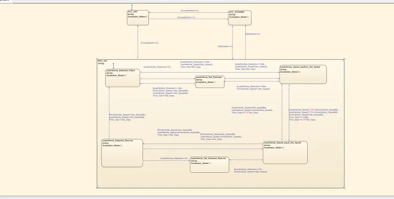
Figure 4: State logic for ACC system.
Simulink Top Level Model:
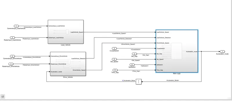
Figure 5 shows the top level model for adaptive cruise control system.
Steps followed during Modelling:
1.Create the model as per the given requirement 1,2,3.
2.Now, create a SLDD file as per the table 1 variable .Select the proper datatype . Figure 7 shows the screenshot for SLDD created for the above project.
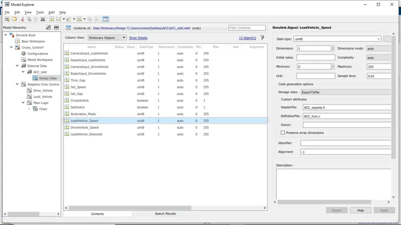
Figure 7: Screenshot for SLDD used for above project
3. Resolve the input and output signal.
4. In chart section also , change the datatype of the variable which are used in the stateflow chart. Figure 8 shows the changes done for chart(stateflow).
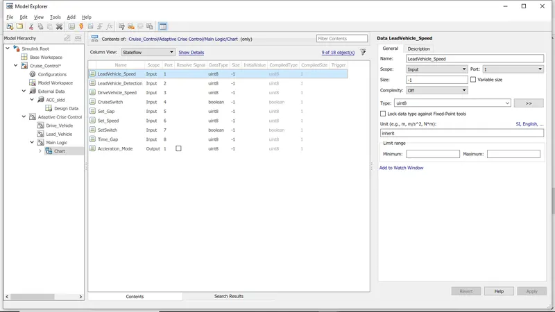
Figure 8: Changes done on the datatype for stateflow/chart
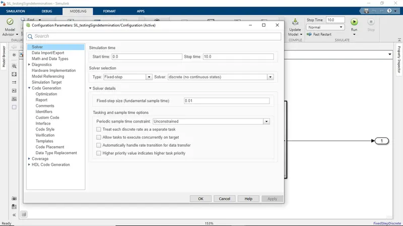
5.Now change the model configuration properties as illustrated in the figure 9.
 `->`
`->`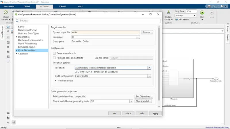
Figure 9: Changes done in Model configuration.
6. Now, run the model.if no error was shown , then the model works fine but if it throws some error than check the model and make the necessary correction.
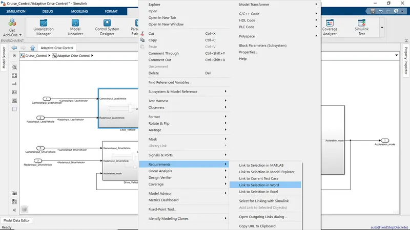
7. Now do the requirement tragging and tracability as per the figure 10.
Generated C code:
*
 * File: Cruise_Control.c
 *
 * Code generated for Simulink model 'Cruise_Control'.
 *
 * Model version                  : 1.23
 * Simulink Coder version         : 9.3 (R2020a) 18-Nov-2019
 * C/C++ source code generated on : Sat Mar  5 14:32:13 2022
 *
 * Target selection: ert.tlc
 * Embedded hardware selection: Intel->x86-64 (Windows64)
 * Code generation objectives: Unspecified
 * Validation result: Not run
 */

#include "Cruise_Control.h"
#include "Cruise_Control_private.h"

/* Named constants for Chart: '/Chart' */
#define Cru_IN_LeadVehicle_Not_Detected ((uint8_T)3U)
#define Cruise_Contr_IN_NO_ACTIVE_CHILD ((uint8_T)0U)
#define Cruise_Control_IN_ACC_OFF      ((uint8_T)1U)
#define Cruise_Control_IN_ACC_ON       ((uint8_T)2U)
#define Cruise_Control_IN_ACC_STANDBY  ((uint8_T)3U)
#define IN_LeadVehicle_Detected_Follow ((uint8_T)1U)
#define IN_LeadVehicle_Detected_Resume ((uint8_T)2U)
#define IN_LeadVehicle_Not_Detected_Res ((uint8_T)4U)
#define IN_LeadVehicle_Speed_equal_Set_ ((uint8_T)5U)
#define IN_LeadVehicle_Speed_lessthan_S ((uint8_T)6U)

/* Block states (default storage) */
DW_Cruise_Control_T Cruise_Control_DW;

/* External outputs (root outports fed by signals with default storage) */
ExtY_Cruise_Control_T Cruise_Control_Y;

/* Real-time model */
RT_MODEL_Cruise_Control_T Cruise_Control_M_;
RT_MODEL_Cruise_Control_T *const Cruise_Control_M = &Cruise_Control_M_;

/* Forward declaration for local functions */
static void Cruise_Control_ACC_ON(void);
real_T rt_roundd_snf(real_T u)
{
  real_T y;
  if (fabs(u) < 4.503599627370496E+15) {
    if (u >= 0.5) {
      y = floor(u + 0.5);
    } else if (u > -0.5) {
      y = u * 0.0;
    } else {
      y = ceil(u - 0.5);
    }
  } else {
    y = u;
  }

  return y;
}

/* Function for Chart: '/Chart' */
static void Cruise_Control_ACC_ON(void)
{
  int32_T tmp;
  uint8_T tmp_0;

  /* Inport: '/SetSwitch' incorporates:
   *  Inport: '/CruiseSwitch'
   *  Inport: '/Set_Gap'
   *  Inport: '/Set_Speed'
   *  Inport: '/Time_Gap'
   */
  if (!SetSwitch) {
    Cruise_Control_DW.is_ACC_ON = Cruise_Contr_IN_NO_ACTIVE_CHILD;
    Cruise_Control_DW.is_c3_Cruise_Control = Cruise_Control_IN_ACC_STANDBY;
  } else if (!CruiseSwitch) {
    Cruise_Control_DW.is_ACC_ON = Cruise_Contr_IN_NO_ACTIVE_CHILD;
    Cruise_Control_DW.is_c3_Cruise_Control = Cruise_Control_IN_ACC_OFF;
  } else {
    switch (Cruise_Control_DW.is_ACC_ON) {
     case IN_LeadVehicle_Detected_Follow:
      if (LeadVehicle_Detected == 0) {
        Cruise_Control_DW.is_ACC_ON = Cru_IN_LeadVehicle_Not_Detected;
      } else if (((LeadVehicle_Detected == 1) && (LeadVehicle_Speed < Set_Speed))
                 || (Time_Gap < Set_Gap)) {
        Cruise_Control_DW.is_ACC_ON = IN_LeadVehicle_Speed_lessthan_S;
      } else {
        /* Update for Outport: '/Accleration_mode' */
        Cruise_Control_Y.Accleration_mode = 2U;
      }
      break;

     case IN_LeadVehicle_Detected_Resume:
      /* Inport: '/Set_Speed' incorporates:
       *  Inport: '/Set_Gap'
       *  Inport: '/Time_Gap'
       */
      if ((DriveVehicle_Speed == Set_Speed) && (LeadVehicle_Speed >= Set_Speed) &&
          (Time_Gap >= Set_Gap)) {
        Cruise_Control_DW.is_ACC_ON = IN_LeadVehicle_Detected_Follow;
      } else if (LeadVehicle_Detected == 0) {
        Cruise_Control_DW.is_ACC_ON = IN_LeadVehicle_Not_Detected_Res;
      } else if ((DriveVehicle_Speed < Set_Speed) && (LeadVehicle_Speed >
                  DriveVehicle_Speed) && (Time_Gap >= Set_Gap)) {
        Cruise_Control_DW.is_ACC_ON = IN_LeadVehicle_Speed_equal_Set_;
      } else {
        /* Update for Outport: '/Accleration_mode' */
        Cruise_Control_Y.Accleration_mode = 3U;
      }
      break;

     case Cru_IN_LeadVehicle_Not_Detected:
      /* Inport: '/Set_Speed' incorporates:
       *  Inport: '/Set_Gap'
       *  Inport: '/Time_Gap'
       */
      if ((LeadVehicle_Detected == 1) && (DriveVehicle_Speed == Set_Speed) &&
          (LeadVehicle_Speed >= Set_Speed) && (Time_Gap >= Set_Gap)) {
        Cruise_Control_DW.is_ACC_ON = IN_LeadVehicle_Detected_Follow;
      } else if (((LeadVehicle_Detected == 1) && (LeadVehicle_Speed < Set_Speed))
                 || (Time_Gap < Set_Gap)) {
        Cruise_Control_DW.is_ACC_ON = IN_LeadVehicle_Speed_lessthan_S;
      } else {
        /* Update for Outport: '/Accleration_mode' */
        Cruise_Control_Y.Accleration_mode = 1U;
      }
      break;

     case IN_LeadVehicle_Not_Detected_Res:
      /* Update for Outport: '/Accleration_mode' */
      Cruise_Control_Y.Accleration_mode = 1U;
      break;

     case IN_LeadVehicle_Speed_equal_Set_:
      /* Inport: '/Set_Speed' incorporates:
       *  Inport: '/Set_Gap'
       *  Inport: '/Time_Gap'
       */
      if (((DriveVehicle_Speed < Set_Speed) && (LeadVehicle_Speed >
            DriveVehicle_Speed)) || (Time_Gap >= Set_Gap)) {
        Cruise_Control_DW.is_ACC_ON = IN_LeadVehicle_Detected_Resume;
      } else if (((LeadVehicle_Speed < Set_Speed) && (LeadVehicle_Speed <
                   DriveVehicle_Speed)) || ((int32_T)rt_roundd_snf(0.75 *
                   (real_T)Set_Gap) == Time_Gap)) {
        Cruise_Control_DW.is_ACC_ON = IN_LeadVehicle_Speed_lessthan_S;
      } else if ((LeadVehicle_Detected == 0) || (DriveVehicle_Speed <= Set_Speed))
      {
        Cruise_Control_DW.is_ACC_ON = IN_LeadVehicle_Not_Detected_Res;
      } else {
        /* Update for Outport: '/Accleration_mode' */
        Cruise_Control_Y.Accleration_mode = 5U;
      }
      break;

     default:
      /* Inport: '/Set_Speed' */
      /* case IN_LeadVehicle_Speed_lessthan_Set_Speed: */
      if ((LeadVehicle_Detected == 0) && (DriveVehicle_Speed == Set_Speed)) {
        Cruise_Control_DW.is_ACC_ON = Cru_IN_LeadVehicle_Not_Detected;
      } else {
        tmp = (int32_T)rt_roundd_snf((real_T)LeadVehicle_Speed * 1.25);
        if (tmp < 256) {
          tmp_0 = (uint8_T)tmp;
        } else {
          tmp_0 = MAX_uint8_T;
        }

        /* Inport: '/Time_Gap' incorporates:
         *  Inport: '/Set_Gap'
         */
        if ((tmp_0 >= DriveVehicle_Speed) && ((int32_T)rt_roundd_snf((real_T)
              LeadVehicle_Speed * 0.75) <= DriveVehicle_Speed) &&
            (DriveVehicle_Speed < Set_Speed) && (Time_Gap <= 1.25) && (Time_Gap >=
             (int32_T)rt_roundd_snf(0.75 * (real_T)Set_Gap))) {
          Cruise_Control_DW.is_ACC_ON = IN_LeadVehicle_Speed_equal_Set_;
        } else {
          /* Update for Outport: '/Accleration_mode' */
          Cruise_Control_Y.Accleration_mode = 4U;
        }
      }
      break;
    }
  }

  /* End of Inport: '/SetSwitch' */
}

/* Model step function */
void Cruise_Control_step(void)
{
  /* Sum: '/Add' incorporates:
   *  Inport: '/CameraInput_LeadVehicle'
   *  Inport: '/RadarInput_LeadVehicle'
   */
  LeadVehicle_Speed = (uint8_T)((uint32_T)CameraInput_LeadVehicle +
    RadarInput_LeadVehicle);

  /* SignalConversion: '/Signal Conversion' incorporates:
   *  Inport: '/RadarInput_DriveVehicle'
   */
  LeadVehicle_Detected = RadarInput_DriveVehicle;

  /* UnitDelay: '/Unit Delay' */
  Accleration_Mode = Cruise_Control_DW.UnitDelay_DSTATE;

  /* Sum: '/Add' incorporates:
   *  Inport: '/CameraInput_DriveVehicle'
   *  Inport: '/RadarInput_DriveVehicle'
   */
  DriveVehicle_Speed = (uint8_T)((uint32_T)(uint8_T)((uint32_T)
    CameraInput_DriveVehicle + Accleration_Mode) + RadarInput_DriveVehicle);

  /* Chart: '/Chart' incorporates:
   *  Inport: '/CruiseSwitch'
   *  Inport: '/SetSwitch'
   */
  if (Cruise_Control_DW.is_active_c3_Cruise_Control == 0U) {
    Cruise_Control_DW.is_active_c3_Cruise_Control = 1U;
    Cruise_Control_DW.is_c3_Cruise_Control = Cruise_Control_IN_ACC_OFF;
  } else {
    switch (Cruise_Control_DW.is_c3_Cruise_Control) {
     case Cruise_Control_IN_ACC_OFF:
      if (CruiseSwitch) {
        Cruise_Control_DW.is_c3_Cruise_Control = Cruise_Control_IN_ACC_STANDBY;
      } else {
        /* Outport: '/Accleration_mode' */
        Cruise_Control_Y.Accleration_mode = 0U;
      }
      break;

     case Cruise_Control_IN_ACC_ON:
      Cruise_Control_ACC_ON();
      break;

     default:
      /* case IN_ACC_STANDBY: */
      if (!CruiseSwitch) {
        Cruise_Control_DW.is_c3_Cruise_Control = Cruise_Control_IN_ACC_OFF;
      } else if (SetSwitch) {
        Cruise_Control_DW.is_c3_Cruise_Control = Cruise_Control_IN_ACC_ON;
        Cruise_Control_DW.is_ACC_ON = IN_LeadVehicle_Detected_Follow;
      } else {
        /* Outport: '/Accleration_mode' */
        Cruise_Control_Y.Accleration_mode = 1U;
      }
      break;
    }
  }

  /* End of Chart: '/Chart' */

  /* Update for UnitDelay: '/Unit Delay' incorporates:
   *  Outport: '/Accleration_mode'
   */
  Cruise_Control_DW.UnitDelay_DSTATE = Cruise_Control_Y.Accleration_mode;
}

/* Model initialize function */
void Cruise_Control_initialize(void)
{
  /* (no initialization code required) */
}

/* Model terminate function */
void Cruise_Control_terminate(void)
{
  /* (no terminate code required) */
}

/*
 * File trailer for generated code.
 *
 * [EOF]
 */
Conclusion:
The model has been developed as per the given requirement and the C code is generated from the model. The model has run successfully and no error was thrown.
Reference:
https://www.extremetech.com/extreme/157172-what-is-adaptive-cruise-control-and-how-does-it-work