Project 2
WIRING HARNESS ROUTING OF BACKDOOR USING CATIA V5
OBJECTIVE: The objectives of this challenge are as given below,
- To Define the mechanical components electrically and prepare a catalog for the same.
- To Provide proper bundle routing without any interference and support parts like clips and clamps.
- To Prepare a report with all the required images required for the challenge.
- Attach all the files required for the challenge.
The first step involved in the Wiring harness design process is "Input Collection".
All the required data like Physical Architecture (gives the location of the components), BOM(Bill of Materials), Vehicle Specification (Assembly sequence and Wet/Dry Zones), and ROX(Return on Experience) from past learning.
The next step is "Data Study". The data from the input collection is studied to understand the assembly sequence and component location, which helps build the "Harness Topology".
The Wiring harness topology is reviewed with the cross-functional teams it is modified if any changes are required. if the topology is approved then the "concept routing" is prepared and it is again reviewed with the cross-functional teams to check manufacturing & service feasibility.
After finalizing the concept routing, the packaging requirement is published to the design team and then the proto Harness drawing is reviewed for supplier feasibility. upon completion, the drawing and prototype are built and it is reviewed with all Cross-functional teams for validation before releasing the harness drawing to production.
Download all the relevant CAD data like Back Door, Connectors and clips & clamps, etc., for Back Door Harness routing(from Grabcad, TE.com & HellermannTyton, etc).
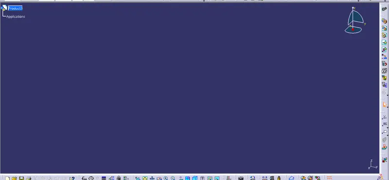
To create the context assembly for routing. Go to File > New > Product and click on OK. Right-click on the product and select properties. Name it "Back Door Wiring Harness Context Assembly" as shown in the below image.
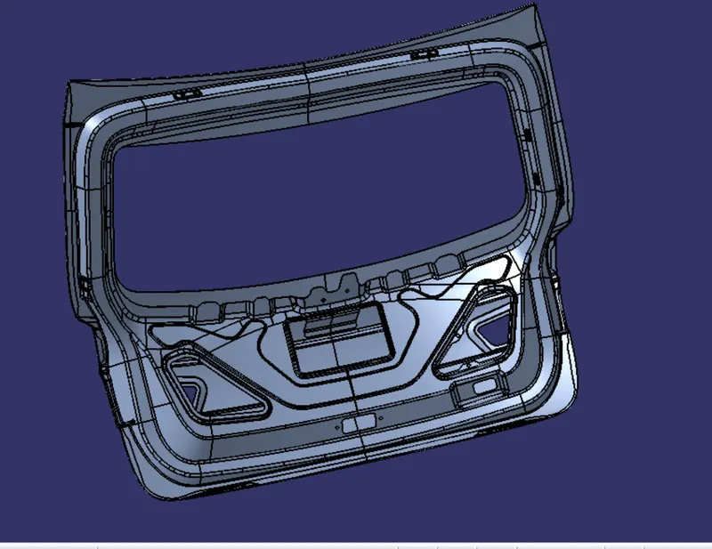
Now add the Back Door 3D Model to the product by right-clicking on the development and going to components and selecting existing components. select the Back Door cad file and click on open.
Since there are two subsystems in our case(Tail tight system and Number plate system) create one Main product named "Back Door_Wiring Harness Assembly" to add the sub-systems.
To create the "Back Door_Wiring Harness Assembly" Product, right-click on the "Back Door Wiring Harness Context Assembly".Go to components > New Product. Right-click on the product, go to properties, and name it "Back Door Wiring Harness Context Assembly".
Before adding the connectors and MOC clips into the geometrical bundle they must be defined electrically. When a component is defined electrically, it can be cross-checked with the "icon change" in the specification tree and publications will also be added.
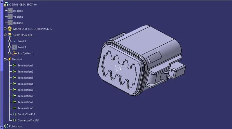
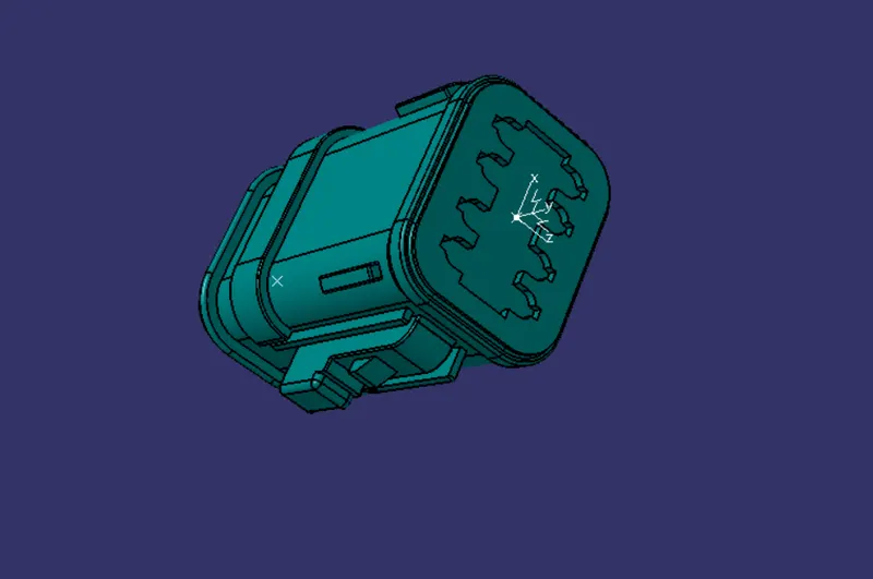
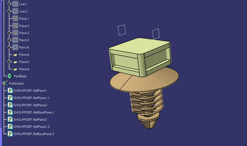
After Defining all the components electrically, add them to the geometrical bundle products as shown in the image below. The connectors can also be added from the Catalogue.
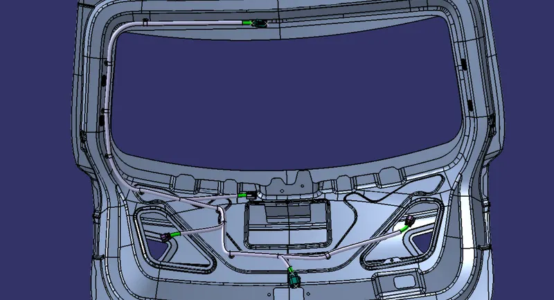
Place the connectors and clips in the required positions and start routing the backdoor. The images of routing are given in below images,
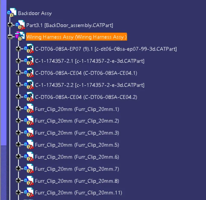
Back Door Routing has to be done to the Tail lights and Number plate lights from the interconnecting connector at the top.
To position, the connectors and clips, and clamps switch to the "Assembly design" module and use the " Manipulation, Snap, Smart move, Translation or Rotation" commands as shown in the below image. position the connectors and MOC fir tree clips according to the routing as shown in the below image.
Ensure that the clips and connector positioning are made in consideration of the Design and Packaging rules. Provide sufficient clearance at necessary places to avoid Fouling. Check whether the minimum distance between the clips is maintained and whether the distance between two clips on a straight bundle should not be more than 200mm. Also, manufacturing and Service feasibility has to be considered to avoid complexity in the production and assembly phases. Routing through small holes and sharp where Chaffing can be avoided. Do not Route over the fasteners or near the fasteners as it may damage (puncture) the harness.
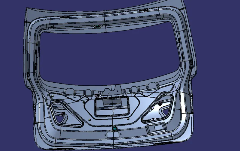
To define the Harness assembly electrically, switch to the Electrical harness Assembly module and click on "geometrical bundle" command and then select the "Tail light Wiring harness geometrical bundle" product. After defining the geometrical bundle electrically the icon changes with a blue symbol, you can cross check with the "icon change" as shown in the below image.
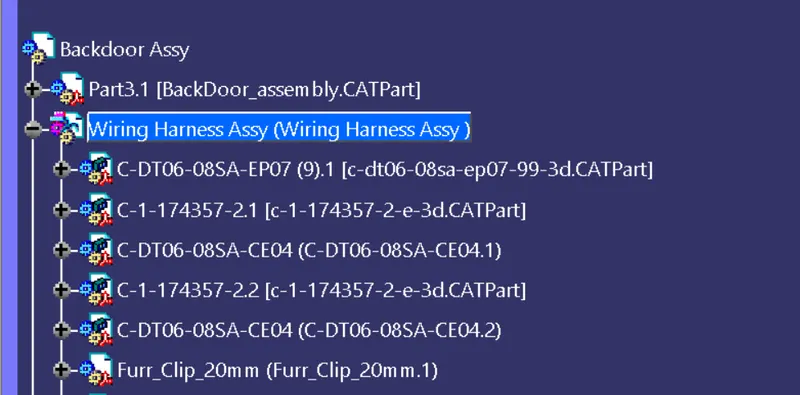
First, finish the routing of the tail light Assembly. The Mutli-Branchable document is created when we start to route the first bundle segment by clicking on the "Branch Definition" command as shown in the below image. Also the module switches to Electrical Harness Installation.
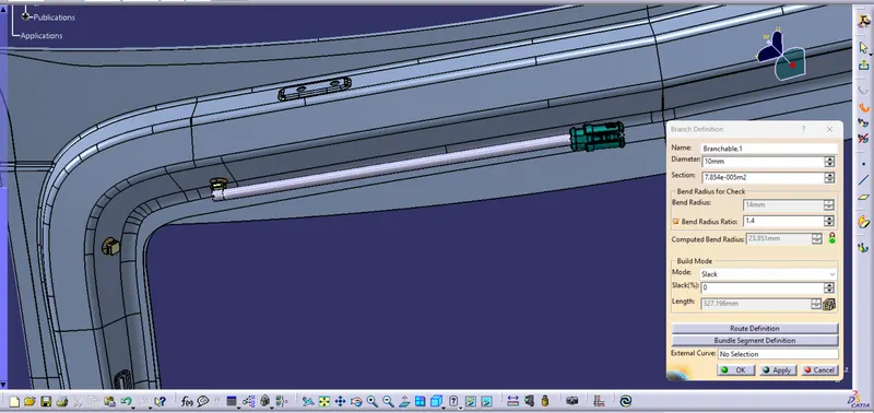
In the Branch definition window, you can set the "Bundle diameter, Bend radius, and slack". The bend radius ratio is usually set to 1.4 and it should not be less than that. Always check that the traffic lights near the computed bend radius are in Green. A little Slack is always added to the bundle segment that is connected to the connector to prevent damage due to tension.
There are various "build modes" available you can also change the mode to length and specify the length of the bundle segment. The bundle segment can also be created along the external curve by clicking on the "external curve" option in the branch definition window and then selecting the curve. This option can be used while routing the bundle inside the Guiding channels.
"Bundle diameter" and "color" can be changed using the "Bundle segments definition" option in the branch definition window. When various concept proposals have Changed color using this option helps us to refer quickly during the reviews.
Generally, Routing is always started from the interconnects and the main trunk is routed first. Then the branch points are created and the bundles are routed from the branch points to the connectors.
Now click on "Route definition" in the branch definition window and then select the interconnect first and then the MOC clip to route the bundle segment as shown in the below image.
you can also add new routing objects in the required order by using the "Add before, Add after and replace" options. For example, when you select the add before the option the new routing object is created before the selected routing object. similarly, replace option creates new routing objects in place of the selected routing object.
Orientation and offset of the bundle segment can be managed by using the "offset management" and "position management" command in the "Route definition" window as shown in the below image.
To change the Tangent orientation you need to select the routing object and then click on the "Reverse Tangent" option.
To set the tangential direction similar to an external curve. select the constraint type as "explicit" under tangent management in the Route definition window.
The automatic option in Offset management is the computer calculated and it is the default option. But, when the routed bundle segment is fouling with the surrounding the "offset with safety margin" can be used to provide the required clearance by specifying the value. To add the control point in the bundle segment for clearing the clash, Press the control key and place the point appropriately.
Now Activate the Number plate light geometrical bundle and Route from the interconnecting connector at the top to the two connectors at the number plate through the MOC clips as shown in the image.
If necessary, Compass can also be used to change the orientation of the clips while routing for easy positioning.
Now continue to route the main trunk to the right tail lamp connector through the MOC Clips mounted as shown in the below image.
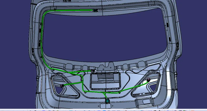
Ensure that Slack is added to the bundle segments that are connected to the connectors to prevent damage due to tension.
The protection(corrugated tubes) can be added from the catalog.
To create CatalogDocument go to File > New > CatalogDocument
Select the "Add Family" Command name Slit COT and select the type conduit. Then, save it locally.
Now go to File > New > Part and create a single part as per the names given in the table by using the "define protection part" command.
Apply the required Id, OD, and thickness. consider the bend length as 1.5 times OD. Click ok and the tube will appear.
Select the storage device command and choose the previously saved catalog and Slit COT family. Click ok.
Using COT tubes of different colors can help identify the sub-system that harnesses belongs to. It is also selected based on the temperature. Cotton tapes are used in extremely hot zones like engines. Generally, battery cables are branded with silica material to offer high protection.
Now Switch back to the Electrical harness assembly module and use the "Protective Covering" command to apply protection to the bundle segments. Browse the catalog, select the COT tube of the required diameter and select the bundle segments(Use the CTRL key to add more bundle segments). Click on OK.
you can change the extremity point by clicking on the "start extremity" and "end extremity". specify the ratio or length and click on ok.
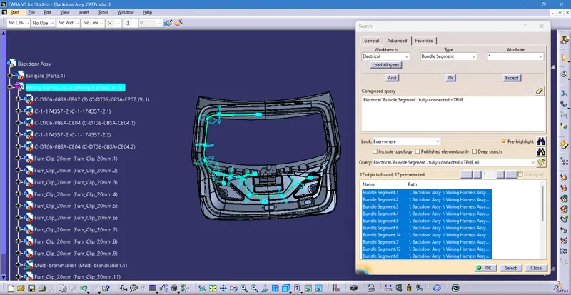
To check the continuity of the bundle segments go to edit > search. Click on the advanced tab. select the workbench as electrical, Type as bundle segment and Attribute as Fully connected. select the false option. Click on the search icon and ensure that no objects are found as shown in the below image. You can also select the true option and click on search and select to check whether all the bundles are connected.
Now, Got to File > New > Product and name it "wiring flattening project 2". Switch to the Electrical harness flattening installation and add the flattening parameters by using the "Harness Flattening Parameters" command as shown in the below image.
Select the active place and the appropriate representation type in the drawing tab as shown in the below image. Click OK and Save the file in the same location as the context assembly.
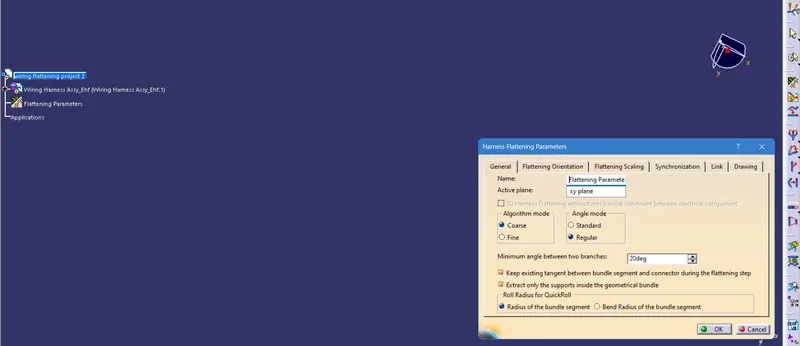
Tile the windows vertically Select the "extract" command and click on the Geometrical bundle product in the Context assembly window to call the harness assembly into the flattening product. Click on the "flatten" command and click on any bundle and enable the select all bundle segments option. Click on ok.

You can use the compass to position the channel, clips, and clamps accordingly. To create links that are created while extraction, use the Auto Update Flatten link, and Manually Update Flatten link commands. and remove links. Also, use the "synchronize" command to update the 3D changes made in the harness assembly.
Use the rotate, roll, straighten, and junction commands to change the branch orientation according to the requirement as shown in the below image.
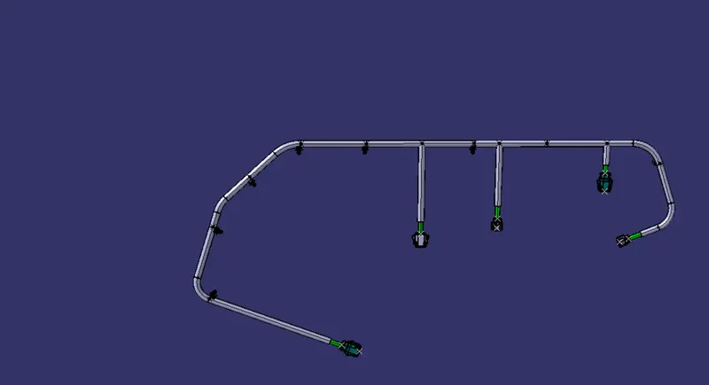
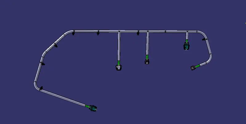
Update if there is any available before Saving it.
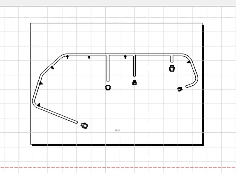
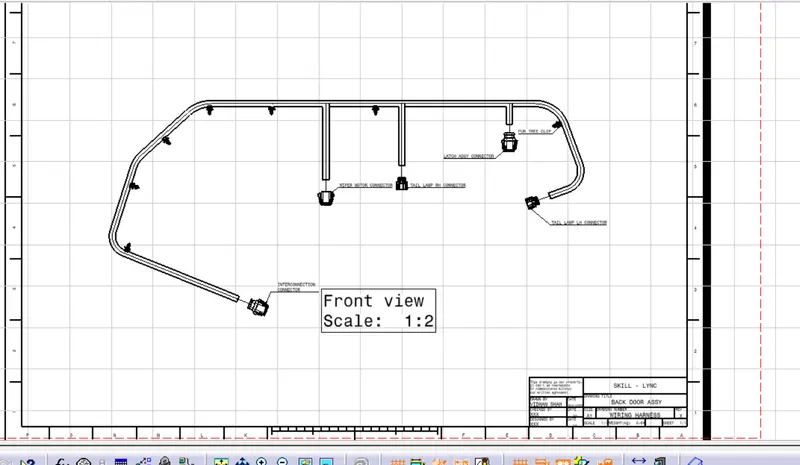
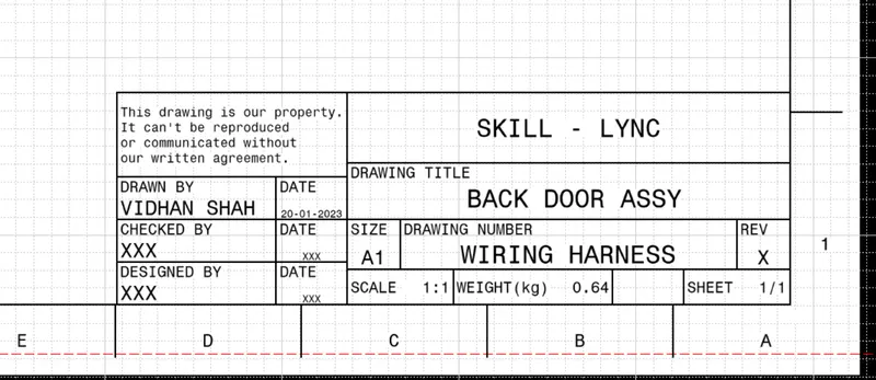
create a new drawing file and name it "Back Door Wiring Harness Drawing". Select the "front view" command and then select the required plane in the Flattened Harness assembly to pull the flattened view into the drawing sheet.
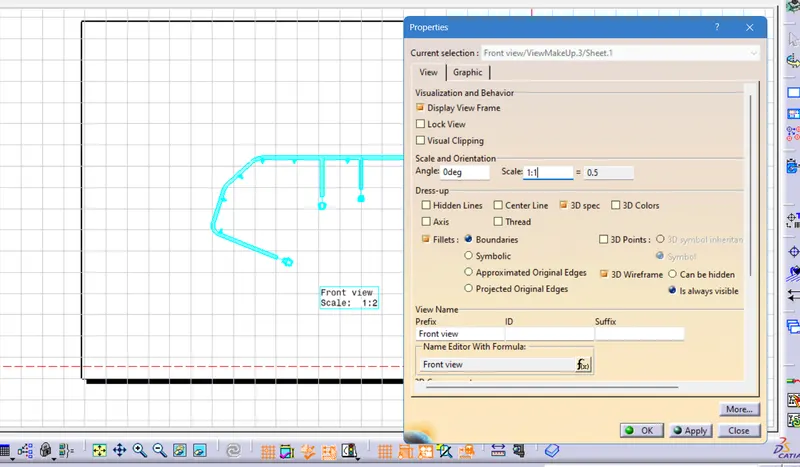
Go to properties and enable the "3D wire frame" option and "3D colors" click ok and save the drawing file.
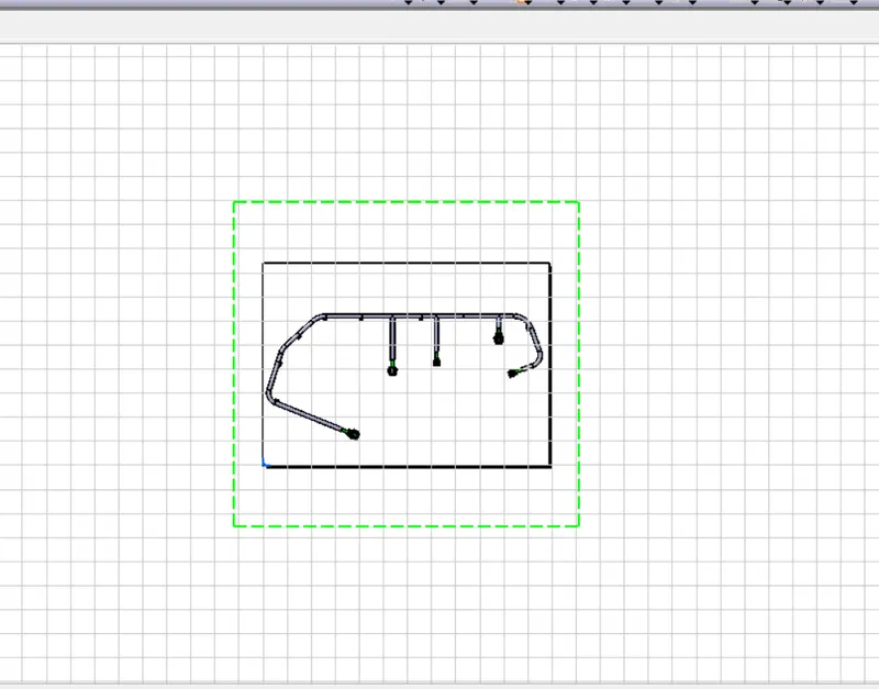
In the end, ensure that context assembly is removed and only the Harness assembly (Containing Geometrical Bundle ) is delivered.