Project 2
1. Initiate a rough concept of Fixture design with reference to all the inputs provided for the given Car panel.
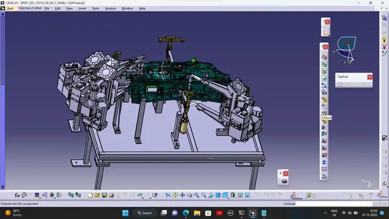
ANS:- Every fixture is designed according to 3-2-1 principle. 6 different fixtures has been developed which includes 3 swivel clamp unit, 1 retractable pin unit, 1 clamp unit and a base unit. Choice of different fixture has been made according to feasibility and requirement.
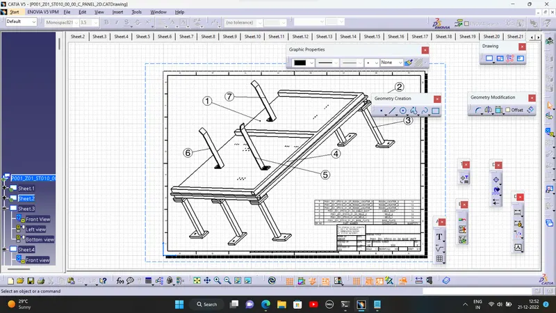
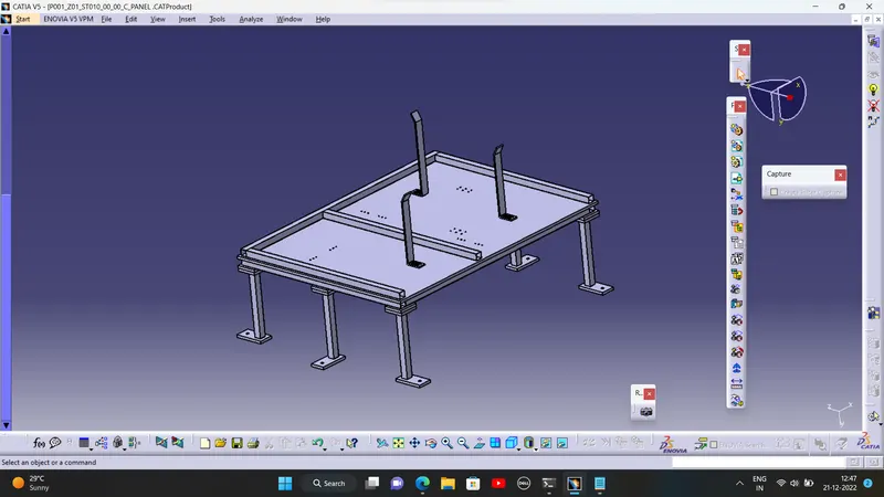
a. Base unit:- It is must required unit. It includes base plate, sq. tube frame, pedestals and floor plate. Base plate is 20 mm thick machined plate. It covers the periphery of every fixture. Basically all the units mounted on base plate. Then base plate is raised to a specific height according to ergo data. As human need to operate fixture so every fixture must be reachable to operator. Then there is floor plate, which is mount over ground with the help of threaded stud. Threaded stud is used for leveling purpose. Rough locators are also used for accurate positioning of panel over fixture. Rough locator guides panel from 15-20mm distance.
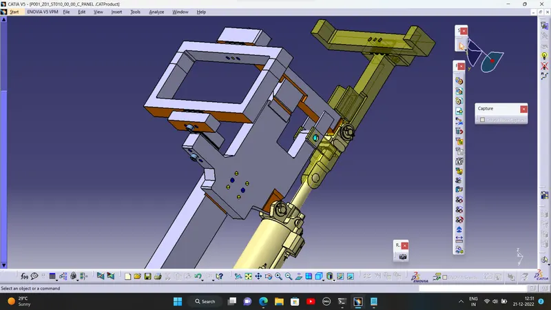
b. Swivel clamp unit:- Swivel clamps are used in three places. This are used becuase, we can use two clamping points with one moving arm. It has clamp mylar, rest mylar, clamp swing arm, blade and riser. In two swivel clamp units rest swing arm is also used. In this units blade is main part. As it connects cylinder, mylars to riser. So blade has number of holes to join different parts and hence it's design and manufacturing is difficult. The mounting of clevis cylinder is also difficult, as we need to maintain 100mm stroke. Bushings are used at every mounting point of cylinder to obtain free rotation. Swing arm is rested over male-female rests. While it is pivoted about pivot arms. For maintaining of 100mm stroke, we need to maintain 50mm of pivot arm at a horizontal distance of 50mm from point of attachment of swing arm to cylinder.
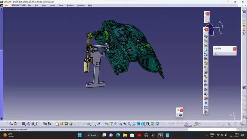
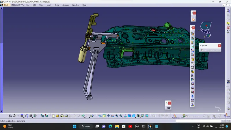
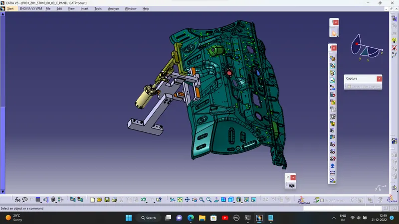
c. Clamp arm:- Unlike swivel clamp unit, this is simple in design and no complex parts included. It contains clamp mylar, rest mylar and riser. Rest mylar is directly attached over riser. Clamp mylar has only one clamping point. In this assemlby all other parts are attched over riser directly.In this particular unit design of rest unit was difficult as car panel had some limitations.
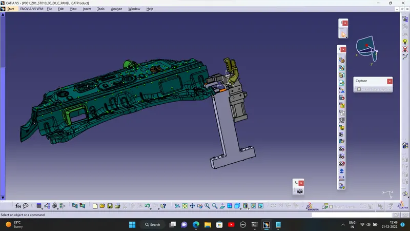
d. Retractable pin unit:- Pin unit used to locate the hole and so it restricts car panel. This is unit is most of the time is not nominal, as pin location cannot be moved. In retractable pin unit, pin retainer is not required. Pin is directly ounted over retractable cylinder. Then cylinder is mounted to riser with help of L-block. This unit is simple in design as no any special constrain is applied.
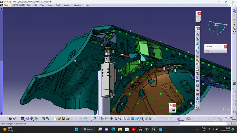
2. Complete 3D finish work.
ANS:- In 3D finish firstly we need to maintain nominality of every unit and its component. Although we cannot place pin unit at nominal position, but other units can be nominal. It will be easy for automatic maching. We need to apply colour coding to dovel holes, bolt holes and machining areas. For dovel holes we apply dark blue colour, while for untreaded portion we apply sky blue colour while for treaded portion yellow colour is applied. For maching area orange colour is applied. While cutting parts with profile cutting corners turns into fillets. So it need to mention while 3D finish. For thickness above 50mm, 5mm of fillet is given while below the 50mm, 3mm of fillet is given. When we do machining that fillets will get erased. So at machining areas we need not to mention fillets. Gun study is also done to verify feasibility of weld spots.
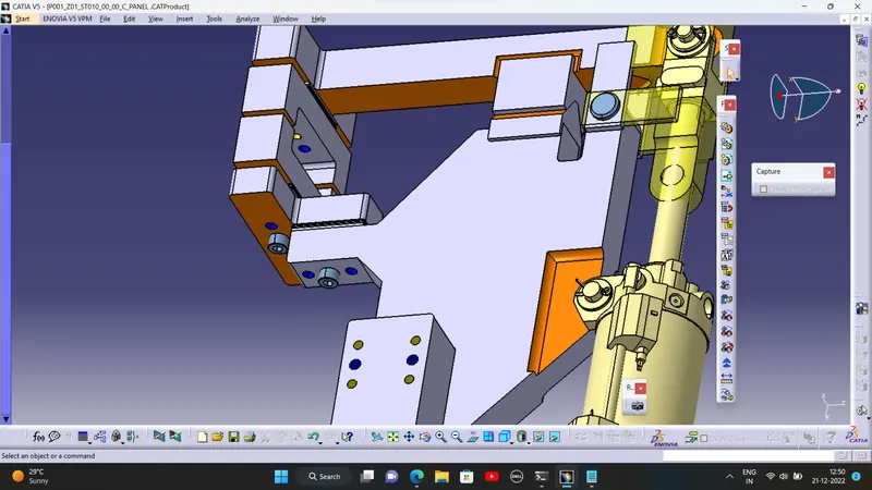
3. Complete 2D finish with Output documentation.
ANS:- 2D finish is necessary for manufacturing purpose. In 2D finish orthogonal as well as isometric of each unit and its component is drawned. Proper dimensions are also given with tolerances. At machining areas machining symbols has to be given. This are some eassential standards to be maintain while 2D finish so that manufacturer can easily connect with the design. For every part while dimensioning we need to give 3 starts for manufacturing purpose and dimensions must be given from that starts only. In documentation BOM and BOP is included. BOM is bill of material. It is list of standard as well manufacturing parts included in assembly. While BOP is bill of parts. This is list of only standard parts that are included in units, with their make and quantities. Generally documentation is done in softwares provided by the customer only.