Project 2
PROJECT 02
AIM:-
To design an interleaving DC/DC converter system for a data centre application with the following specifications:
• Input voltage: 45 – 60 v
• Output voltage: 3 V
• Output current: 100A
• Efficiency > 85%
Here we have to design a 300W step down converter which reduced the voltage level from a range
of 45-60V to 3V.
We will use a Isolated converter for Load security and effeciency ( Forward converter )
The forward converter is a DC/DC converter that uses a transformer to increase or decrease the output voltage (depending on the transformer ratio) and provide isolation for the load.
We know, Duty cycle (D)

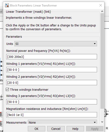
Np = Primary turns
Ns = Secondary turns
Nt = Teritery turns
Let,s design our forward converter for 50% Duty
=> Vout = 0.5(Ns/Np)Vin
=> Ns/Np = 0.12
Lets choose Ns = 100
=>100/Np = 0.12
=> Np = 833.3
Since we choose D = 50%
=> D<(1-Nt/Np)<1
=> Nt/Np <1
=> so we will choose Nt = 500
Also The load resistance
R = Vout^2/P = 0.03ohm
IL = Vout/R = 100A
We will design the inductor for 20% current ripple
=> Delta(IL) = 0.2*IL = 0.2*100 = 20A
=> L = Vout/(Fs*delta(IL)) = 7.5e-7H
Similerly we will design the capacitor for 5% ripple as
Delta(Vout) = 0.05*Vout = 0.15v
Delta(vout)/Vout = 0.05V
=>C= (1-D)/(8*L*Fs^2(Delta(Vout)/Vout)))
=>C = 4.166e-5f
Now We will build a design for our model in Simulink as
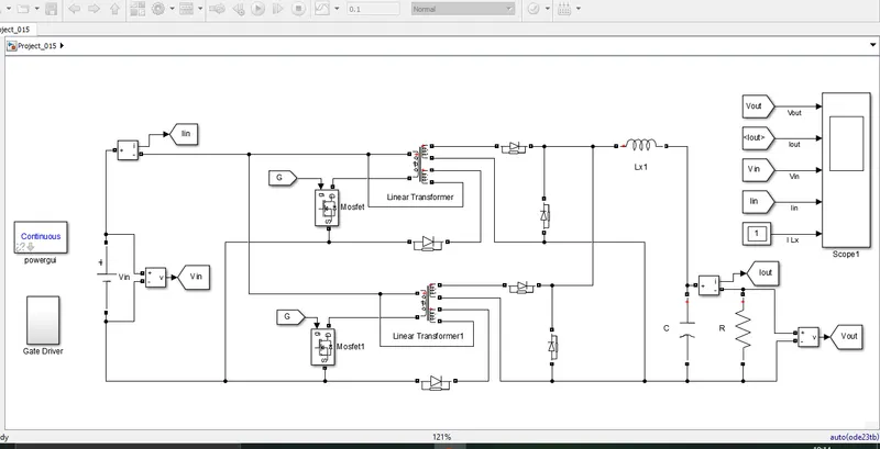
Here we are using a multi phase system of two parallel converters to increase the effeciency.
but if we go beyond five phases the effeciency ill sytill get better but, the cost will also increase.
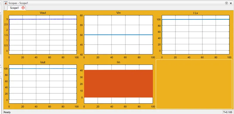
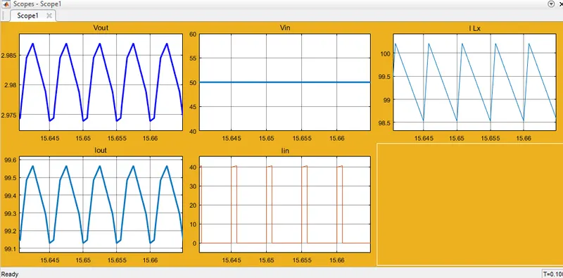
After running the model in simulink we get the output result as.
Zoomed out
Zoomed in
PWM output
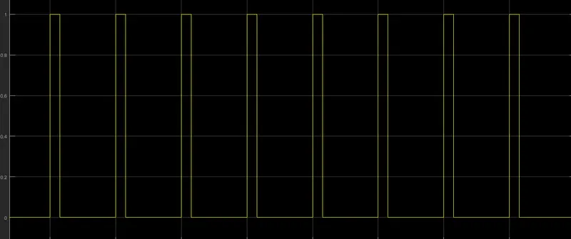
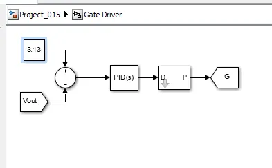
Gate driver
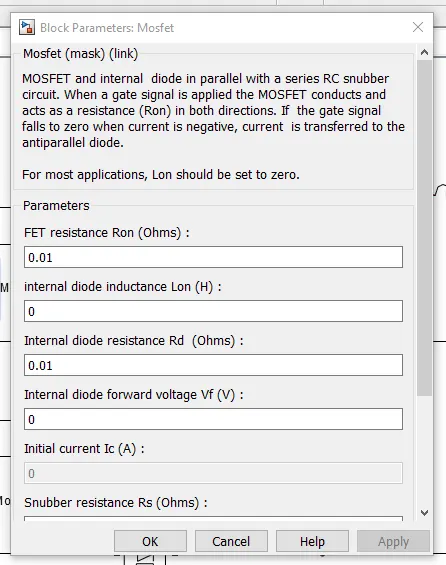
Mosfet used
Transformer used
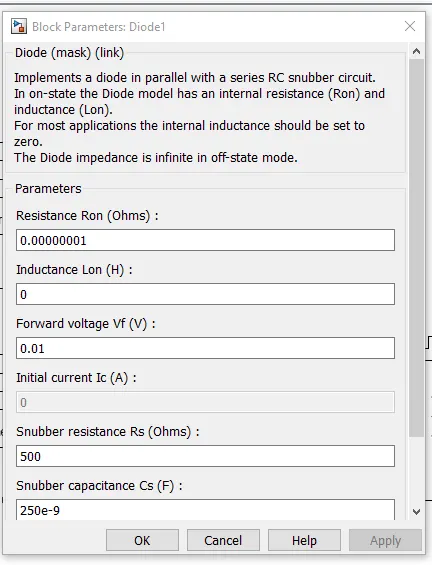
Diode used
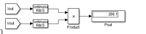
Output power
KINDLY FIND THE ATTACHED FILES BELOW.
-------------------------------------------END------------------------------------
-------------------------------------------END------------------------------------